Page 2731 of 4592

L = 180 mm (7.09 in.)L = 72 mm (2.83 in.)
L = 335 mm (13.19 in.)L = 180 mm
(7.09 in.)
L = Length Join
LineJoin
Line
Z14262New Gasket
A01808
8
6
5
4
3
2
1
9
10
7
11
EM")
A05194
L = 133 mm (5.24 in.)
L = 180 mm (7.09 in.)L = 72 mm (2.83 in.)
L = 335 mm (13.19 in.)L = 180 mm
(7.09 in.)
L = Length Join
LineJoin
Line
Z14262New Gasket
A01808
8
6
5
4
3
2
1
9
10
7
11
EM±66
± ENGINE MECHANICAL (1MZ±FE)CYLINDER HEAD
1352 Author�: Date�: �
Remove the backing paper from a new gasket and
install the gasket evenly to the part of the timing belt
cover shaded black in the illustration.
NOTICE:
When joining 2 gaskets, do not leave a gap between them.
Cut off any excess gasket.
�After installing the gasket, press down on it so that
the adhesive firmly sticks to the timing belt cover.
(b) Install the timing belt cover with the 6 bolts.
Torque: 8.5 N´m (85 kgf´cm, 74 in.´lbf)
(c) Install the 3 engine wire clamps to the timing belt cover.
20. INSTALL NO.2 IDLER PULLEY (See page EM±21)
21. INSTALL CAMSHAFT TIMING PULLEYS
(See page EM±21)
22. INSTALL TIMING BELT (See page EM±21)
23. INSTALL SPARK PLUGS
24. INSTALL IGNITION COILS
25. INSTALL PS PUMP DRIVE BELT
26. INSTALL GENERATOR DRIVE BELT
(See page SR±28)
27. INSTALL WATER OUTLET
(a) Install 2 new gaskets.
(b) Connect the water outlet to the bypass hose.
(c) Install the water outlet with the 2 bolts, 2 nuts and 2 plate
washers. Alternately tighten the bolts and nuts.
Torque: 15 N´m (150 kgf´cm, 11 ft´lbf)
NOTICE:
Do not scratch the seal surface of the water outlet with the
stud bolt.
(d) Connect the ECT sender gauge connector.
(e) Connect the ECT sensor connector.
(f) Connect the ground strap (connector).
(g) Connect the radiator hose.
(h) Connect the engine coolant reservoir hose.
28. INSTALL INTAKE MANIFOLD ASSEMBLY
(a) Install the intake manifold, delivery pipe and injectors as-
sembly with the 9 bolts, 2 plate washers and 2 nuts. Uni-
formly tighten the bolts and nuts, in several passes, in the
sequence shown.
Torque: 15 N´m (150 kgf´cm, 11 ft´lbf)
Page 2841 of 4592

HSGHousing
HTHard Top
HWSHeated Windshield System
IACIdle Air Control
ICIntegrated circuit
IDIIndirect Diesel Inj")
IN±38
± INTRODUCTIONTERMS
38 Author�: Date�:
HIDHigh Intensity Discharge (Head Lamp)
HSGHousing
HTHard Top
HWSHeated Windshield System
IACIdle Air Control
ICIntegrated circuit
IDIIndirect Diesel Injection
IFSIndependent Front Suspension
IGIgnition
IIAIntegrated Ignition Assembly
INIntake (Manifold, Valve)
INTIntermittent
I/PInstrument Panel
IRSIndependent Rear Suspension
J/BJunction Block
J/CJunction Connector
KDKick±Down
LANLocal Area Network
LBLiftback
LCDLiquid Crystal Display
LEDLight Emitting Diode
LHLeft±Hand
LHDLeft±Hand Drive
L/H/WLength, Height, Width
LLCLong±Life Coolant
LNGLiquified Natural Gas
LOLow
LPGLiquified Petroleum Gas
LSDLimited Slip Differential
LSP & PVLoad Sensing Proportioning And Bypass Valve
LSPVLoad Sensing Proportioning Valve
MAX.Maximum
MICMicrophone
MILMalfunction Indicator Lamp
MIN.Minimum
MPMultipurpose
MPXMultiplex Communication System
M/TManual Transmission
MTMount
MTGMounting
NNeutral
NANatural Aspiration
No.Number
O/DOverdrive
OEMOriginal Equipment Manufacturing
OHCOverhead Camshaft
Page 2882 of 4592

HSGHousing
HTHard Top
HWSHeated Windshield System
IACIdle Air Control
ICIntegrated circuit
IDIIndirect Diesel Inj")
IN±36
± INTRODUCTIONTERMS
36 Author�: Date�:
HIDHigh Intensity Discharge (Head Lamp)
HSGHousing
HTHard Top
HWSHeated Windshield System
IACIdle Air Control
ICIntegrated circuit
IDIIndirect Diesel Injection
IFSIndependent Front Suspension
IGIgnition
IIAIntegrated Ignition Assembly
INIntake (Manifold, Valve)
INTIntermittent
I/PInstrument Panel
IRSIndependent Rear Suspension
J/BJunction Block
J/CJunction Connector
KDKick±Down
LANLocal Area Network
LBLiftback
LCDLiquid Crystal Display
LEDLight Emitting Diode
LHLeft±Hand
LHDLeft±Hand Drive
L/H/WLength, Height, Width
LLCLong±Life Coolant
LNGLiquified Natural Gas
LOLow
LPGLiquified Petroleum Gas
LSDLimited Slip Differential
LSP & PVLoad Sensing Proportioning And Bypass Valve
LSPVLoad Sensing Proportioning Valve
MAX.Maximum
MICMicrophone
MILMalfunction Indicator Lamp
MIN.Minimum
MPMultipurpose
MPXMultiplex Communication System
M/TManual Transmission
MTMount
MTGMounting
NNeutral
NANatural Aspiration
No.Number
O/DOverdrive
OEMOriginal Equipment Manufacturing
OHCOverhead Camshaft
Page 2889 of 4592
OIL AND FILTER
1648 Author�: Date�:
REPLACEMENT
CAUTION:
�Prolonged and repeated contact with mineral oil will
result in the removal of natura")
LU03I±03
S05318
SST
S05319
LU±2
± LUBRICATION (5S±FE)OIL AND FILTER
1648 Author�: Date�:
REPLACEMENT
CAUTION:
�Prolonged and repeated contact with mineral oil will
result in the removal of natural fats from the skin,
leading to dryness, irritation and dermatitis. In addi-
tion, used engine oil contains potentially harmful
contaminants which may cause skin cancer.
�Care should be taken, therefore, when changing en-
gine oil to minimize the frequency and length of time
your skin is exposed to used engine oil. Protective
clothing and gloves that cannot be penetrated by oil
should be worn. The skin should be thoroughly
washed with soap and water, or use water±less hand
cleaner, to remove any used engine oil. Do not use
gasoline, thinners, or solvents.
�In order to preserve the environment, used oil and
used oil filters must be disposed of only at desig-
nated disposal sites.
1. DRAIN ENGINE OIL
(a) Remove the oil filler cap.
(b) Remove the oil drain plug, and drain the oil into a contain-
er.
2. REPLACE OIL FILTER
(a) Using SST, remove the oil filter.
SST 09228±06501
(b) Clean the oil filter contact surface on the oil filter mount-
ing.
(c) Lubricate the filter rubber gasket with clean engine oil.
(d) Tighten the oil filter by hand until the rubber gasket con-
tacts the seat of the filter mounting.
Page 2900 of 4592

± LUBRICATION (5S±FE)OIL PUMP
LU±13
1659 Author�: Date�:
INSTALLATION
1. INSTALL OIL PUMP
Install")
LU03P±03
Z19249
A
BB AA A AA A
A A
A
S05928
LU0420
Seal Width
3 ± 5 mm
A
A
BBC
C
5 mm (0.20 in.)
± LUBRICATION (5S±FE)OIL PUMP
LU±13
1659 Author�: Date�:
INSTALLATION
1. INSTALL OIL PUMP
Install a new gasket and the oil pump with the 12 bolts. Uniformi-
ty tighten the bolts in several passes.
Torque: 8.8 N´m (90 kgf´cm, 78 in.´lbf)
HINT:
Each bolt length is indicated in the illustration.
Bolt length:
25 mm (0.98 in.) for A
35 mm (1.38 in.) for B
2. INSTALL OIL PUMP PULLEY (See page EM±23)
3. INSTALL CRANKSHAFT TIMING PULLEY
(See page EM±23)
4. INSTALL NO.2 IDLER PULLEY (See page EM±23)
5. INSTALL TIMING BELT (See page EM±23)
6. INSTALL OIL STRAINER
Install a new gasket and the oil strainer with the bolt and 2 nuts.
Torque: 5.4 N´m (55 kgf´cm, 48 in.´lbf)
7. INSTALL OIL PAN
(a) Remove any old seal packing (FIPG) material and be
careful not to drop any oil on the contact surfaces of the
oil pan and cylinder block.
�Using a razor blade and gasket scraper, remove all
the old packing (FIPG) material from the gasket sur-
faces and sealing groove.
�Thoroughly clean all components to remove all the
loose material.
�Using a non±residue solvent, clean both sealing
surface.
NOTICE:
Do not use a solvent which will affect the painted surfaces.
(b) Apply seal packing to the oil pan shown in the illustration.
Seal packing: Part No. 08826±00080 or equivalent
�Install a nozzle that has been cut to a 3 ± 5 mm (0.12
± 0.20 in.) opening.
�Parts must be assembled within 5 minutes of ap-
plication. Otherwise the material must be removed
and reapplied.
Page 2908 of 4592
OIL AND FILTER
LU±3
1667 Author�: Date�:
REPLACEMENT
CAUTION:
�Prolonged and repeated contact with mineral oil wil")
LU026±03
P12486
P12580
SST
P12582
SST
Additional
3/4 Turn
± LUBRICATION (1MZ±FE)OIL AND FILTER
LU±3
1667 Author�: Date�:
REPLACEMENT
CAUTION:
�Prolonged and repeated contact with mineral oil will
result in the removal of natural fats from the skin,
leading to dryness, irritation and dermatitis. In addi-
tion, used engine oil contains potentially harmful
contaminants which may cause skin cancer.
�Exercise caution in order to minimize the length and
frequency of contact of your skin to used oil. Wear
protective clothing and gloves. Wash your skin thor-
oughly with soap and water, or use water±less hand
cleaner, to remove any used engine oil. Do not use
gasoline, thinners, or solvents.
�In order to preserve the environment, used oil and
used oil filter must be disposed of only at designated
disposal sites.
1. DRAIN ENGINE OIL
(a) Remove the oil filler cap.
(b) Remove the oil drain plug, and drain the oil into a contain-
er.
2. REPLACE OIL FILTER
(a) Using SST, remove the oil filter.
SST 09228±07501
(b) Check and clean the oil filter installation surface.
(c) Apply clean engine oil to the gasket of a new oil filter.
(d) Lightly screw the oil filter into place, and tighten it until the
gasket contacts the seat.
(e) Using SST, tighten it an additional 3/4 turn.
SST 09228±07501
Page 2929 of 4592
MA0055
MA00M±01
MA±6
± MAINTENANCEBRAKE
49 Author�: Date�:
BRAKE
INSPECTION
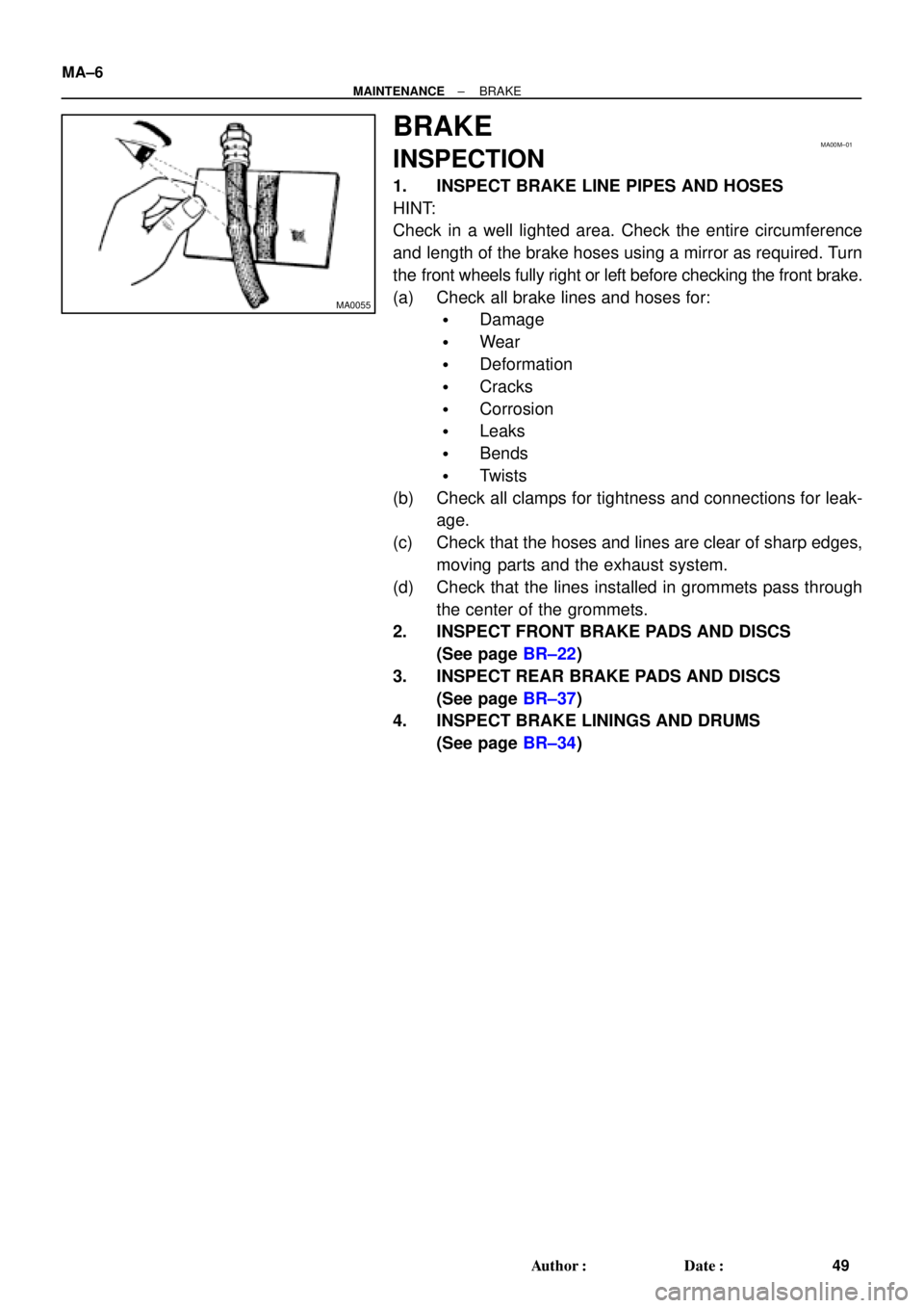
1. INSPECT BRAKE LINE PIPES AND HOSES
HINT:
Check in a well lighted area. Check the entire circumference
and length of the brake hoses using a mirror as required. Turn
the front wheels fully right or left before checking the front brake.
(a) Check all brake lines and hoses for:
�Damage
�Wear
�Deformation
�Cracks
�Corrosion
�Leaks
�Bends
�Twists
(b) Check all clamps for tightness and connections for leak-
age.
(c) Check that the hoses and lines are clear of sharp edges,
moving parts and the exhaust system.
(d) Check that the lines installed in grommets pass through
the center of the grommets.
2. INSPECT FRONT BRAKE PADS AND DISCS
(See page BR±22)
3. INSPECT REAR BRAKE PADS AND DISCS
(See page BR±37)
4. INSPECT BRAKE LININGS AND DRUMS
(See page BR±34)
Page 3125 of 4592
PP0MS±01
PP±100
± PREPARATIONSUPPLEMENTAL RESTRAINT SYSTEM
152 Author�: Date�:
EQUIPMENT
Torque wrench
Bolt: Length: 35 mm (1.38 in.) Pitch: 1.0 mm (0.039 in.)
Diam.: 6.0 mm (0.236 in.)Airbag disposal
Tire Width: 185 mm (7.28 in.) Inner diam.: 360mm (14.17 in.)Airbag disposal
Tire with disc wheel Width: 185 mm (7.28 in.)
Inner diam.: 360 mm (14.17 in.)Airbag disposal
Vinyl bagAirbag disposal