Page 2573 of 4592
TIMING BELT
1194 Author�: Date�:
INSPECTION
1. INSPECT TIMING BELT
NOTICE:
�Do not bend, twist or turn the t")
EM085±03
EM3336
No!
S01519
Turn
Seal
P15243Free Length EM±22
± ENGINE MECHANICAL (5S±FE)TIMING BELT
1194 Author�: Date�:
INSPECTION
1. INSPECT TIMING BELT
NOTICE:
�Do not bend, twist or turn the timing belt inside out.
�Do not allow the timing belt to come into contact with
oil, water or steam.
�Do not utilize timing belt tension when installing or re-
moving the mounting bolt of the camshaft timing
pulley.
If there are any defects as shown in the illustration, check these
points:
(a) Premature parting
�Check for proper installation.
�Check the timing cover gasket for damage and
proper installation.
(b) If the belt teeth are cracked or damaged, check to see if
either camshaft or water pump is locked.
(c) If there is noticeable wear or cracks on the belt face,
check to see if there are nicks on the side of the idler
pulley lock.
(d) If there is wear or damage on only one side of the belt,
check the belt guide and the alignment of each pulley.
(e) If there is noticeable wear on the belt teeth, check the tim-
ing cover for damage and check gasket has been
installed correctly and for foreign material on the pulley
teeth.
If necessary, replace the timing belt.
2. INSPECT IDLER PULLEYS
(a) Visually check the seal portion of the idler pulley for oil
leakage.
If leakage is found, replace the idler pulley.
(b) Check that the idler pulley turns smoothly.
If necessary, replace the idler pulley.
3. INSPECT TENSION SPRING
(a) Measure the free length of tension spring.
Free length: 42.0 mm (1.654 in.)
If the free length is not as specified, replace the tension spring.
(b) Measure the tension of the tension spring at the specified
installed length.
Installed tension (at 50.5 mm (1.988 in.)):
32 ± 37 N (3.25 ± 3.75 kgf, 7.2 ± 8.3 lbf)
If the installed tension is not as specified, replace the tension
spring.
Page 2575 of 4592
 EM±24
± ENGINE MECHANICAL (5S±FE)TIMING BELT
1196 Author�: Date�:
5. TEMPORARILY INSTALL TIMING BELT
NOTICE:
The engine should be cold.
(a) Us")
S05574
S05944
S05578
P25230Length = 660 mm (25.98 in.) EM±24
± ENGINE MECHANICAL (5S±FE)TIMING BELT
1196 Author�: Date�:
5. TEMPORARILY INSTALL TIMING BELT
NOTICE:
The engine should be cold.
(a) Using the crankshaft pulley bolt, turn the crankshaft and
align the timing marks of the crankshaft timing pulley and
oil pump body.
(b) Remove any oil or water on the crankshaft pulley, oil
pump pulley, water pump pulley, No.1 idler pulley and
No.2 idler pulley, and keep them clean.
(c) Install the timing belt on the crankshaft timing pulley, oil
pump pulley, No.1 idler pulley, water pump pulley and
No.2 idler pulley.
HINT:
When re±using timing belt:
Align the points marked during removal, and install the belt with
the arrow pointing in the direction of engine revolution.
6. INSTALL TIMING BELT GUIDE
Install the guide, facing the cup side outward.
7. INSTALL NO.1 TIMING BELT COVER
(a) Check that the timing belt cover gasket has no cracks or
peeling, etc.
If the gasket has cracks or peeling, etc., replace it using these
steps:
(1) Using a screwdriver and gasket scraper, remove all
the old gasket material.
(2) Thoroughly clean all components to remove all the
loose material.
(3) Remove the backing paper from a new gasket and
install the gasket evenly to the part of the timing belt
cover shaded black in the illustration.
(4) After installing the gasket, press down on it so that
the adhesive firmly sticks to the timing belt cover.
Page 2576 of 4592
TIMING BELT
EM±25
1197 Author�: Date�:
(b) Install the timing belt cover with the 4 bolts.
(c) Install the")
A02591
S05588
SSTSST
S05592
SST
SST
Fulcrum
Length
S05587
Turn
± ENGINE MECHANICAL (5S±FE)TIMING BELT
EM±25
1197 Author�: Date�:
(b) Install the timing belt cover with the 4 bolts.
(c) Install the clamp of the crankshaft position sensor wire to
the timing belt cover.
(d) Install the crankshaft position sensor wire to the clamp on
the timing belt cover.
8. INSTALL CRANKSHAFT PULLEY
(a) Align the pulley set key with the key groove of the pulley,
and slide on the pulley.
(b) Using SST (and bolt), install the pulley bolt.
SST 09213±54015 (91651±60855),09330±00021
Torque: 108 N´m (1,100 kgf´cm, 80 ft´lbf)
HINT:
Either of 2 types of pulley may be used, each with its own bolt
size, type A (91651±60855) and type B
(part No. 91121±40665).
9. INSTALL CAMSHAFT TIMING PULLEY
(a) Align the camshaft knock pin with the knock pin groove of
the pulley, and slide on the timing pulley.
(b) Using SST, install the pulley bolt.
SST 09249±63010, 09960±10010 (09962±01000,
09963±01000)
Torque:
54 N´m (550 kgf´cm, 40 ft´lbf)
37 N´m (380 kgf´cm, 27 ft´lbf) for use with SST
HINT:
Use a torque wrench with a fulcrum length of 340 mm (13.39
in.).
10. SET NO.1 CYLINDER TO TDC/COMPRESSION
(a) Turn the crankshaft pulley, and align its groove with timing
mark º0º of the No.1 timing belt cover.
Page 2578 of 4592

Length = 230 mm (9.06 in.)
± ENGINE MECHANICAL (5S±FE)TIMING BELT
EM±27
1199 Author�: Date�:
(b) Slowly turn the crankshaft")
S05587
Turn
S05598
S05586
Turn
S05585
S01710
Length = 735 mm (28.94 in.)
Length = 230 mm (9.06 in.)
± ENGINE MECHANICAL (5S±FE)TIMING BELT
EM±27
1199 Author�: Date�:
(b) Slowly turn the crankshaft pulley 2 revolutions TDC to
TDC.
NOTICE:
Always turn the crankshaft pulley clockwise.
(c) Check that each pulley aligns with the timing marks as
shown in the illustration.
If the timing marks do not align, remove the timing belt and rein-
stall it.
(d) Slowly turn the crankshaft pulley 1 and 7/8 revolutions,
and align its groove with the mark at 45° BTDC (for No.1
cylinder) of the No.1 timing belt cover.
NOTICE:
Always turn the crankshaft pulley clockwise.
(e) Tighten the mounting bolt of the No.1 idler pulley.
Torque: 42 N´m (425 kgf´cm, 31 ft´lbf)
13. INSTALL NO.2 TIMING BELT COVER
(a) Check that the timing belt cover gaskets have no cracks
or peeling, etc.
If the gasket has cracks or peeling, etc., replace it using these
steps:
(1) Using a screwdriver and gasket scraper, remove all
the old gasket material.
(2) Thoroughly clean all components to remove all the
loose material.
Page 2589 of 4592
CYLINDER HEAD
1210 Author�: Date�:
(2) Secure the exhaust camshaft sub±gear to drive
gear w")
P03445
Drive Gear
Service
Bolt
Sub±Gear
P03356
P03241
3
26 54
1
P03357
EM±38
± ENGINE MECHANICAL (5S±FE)CYLINDER HEAD
1210 Author�: Date�:
(2) Secure the exhaust camshaft sub±gear to drive
gear with a service bolt.
Recommended service bolt:
Thread diameter6 mm
Thread pitch1.0 mm
Bolt length16 ± 20 mm (0.63 ± 0.79 in.)
HINT:
When removing the camshaft, make sure that the torsional
spring force of the sub±gear has been eliminated by the above
operation.
(3) Remove the 2 bolts and rear bearing cap.
(4) Uniformly loosen and remove the 6 bolts on the
No.1, No.2 and No.4 bearing caps in several
passes, in the sequence shown.
NOTICE:
Do not remove the No.3 bearing cap bolts at this stage.
(5) Remove the No.1, No.2 and No.4 bearing caps.
(6) Alternately loosen and remove the 2 bolts on the
No.3 bearing cap.
HINT:
�As the 2 No.3 bearing cap bolts are loosened, make sure
that the camshaft is lifted out straight and level.
�If the camshaft is not being lifted out straight and level, re-
tighten the 2 No.3 bearing cap bolts. Then reverse the or-
der of above steps from (6) to (1) and reset the knock pin
of the intake camshaft at 10 ± 45° BTDC, and repeat
steps from (2) to (6) once again.
NOTICE:
Do not pry on or attempt to force the camshaft with a tool
or other object.
(7) Remove the No.3 bearing cap and exhaust cam-
shaft.
Page 2596 of 4592
CYLINDER HEAD
EM±45
1217 Author�: Date�:
(d) Check the valve overall length.
Standard overall length:")
EM2534
Overall Length
EM0255
P03272
45° Carbide
Cutter
Z00055
Width
± ENGINE MECHANICAL (5S±FE)CYLINDER HEAD
EM±45
1217 Author�: Date�:
(d) Check the valve overall length.
Standard overall length:
Intake97.40 ± 97.80 mm (3.8346 ± 3.8504 in.)
Exhaust98.25 ± 98.65 mm (3.8681 ± 3.8839 in.)
Minimum overall length:
Intake97.1 mm (3.823 in.)
Exhaust98.0 mm (3.858 in.)
If the overall length is less than minimum, replace the valve.
(e) Check the surface of the valve stem tip for wear.
If the valve stem tip is worn, resurface the tip with a grinder or
replace the valve.
NOTICE:
Do not grind off more than the minimum length.
8. INSPECT AND CLEAN VALVE SEATS
(a) Using a 45° carbide cutter, resurface the valve seats.
Remove only enough metal to clean the seats.
(b) Check the valve seating position.
Apply a light coat of prussian blue (or white lead) to the
valve face. Lightly press the valve against the seat. Do not
rotate valve.
(c) Check the valve face and seat for the following:
�If blue appears 360° around the face, the valve is
concentric. If not, replace the valve.
�If blue appears 360° around the valve seat, the
guide and face are concentric. If not, resurface the
seat.
�Check that the seat contact is in the middle of the
valve face with the following width:
1.0 ± 1.4 mm (0.039 ± 0.055 in.)
Page 2597 of 4592
Z02852
45°
30°
1.0 ± 1.4 mm
Z02853
45° 75°
1.0 ± 1.4 mm
P03273
EM0988
Deviation
EM0801
EM±46
± ENGINE MECHANICAL (5S±FE)CYLINDER HEAD
1218 Author�: Date�:
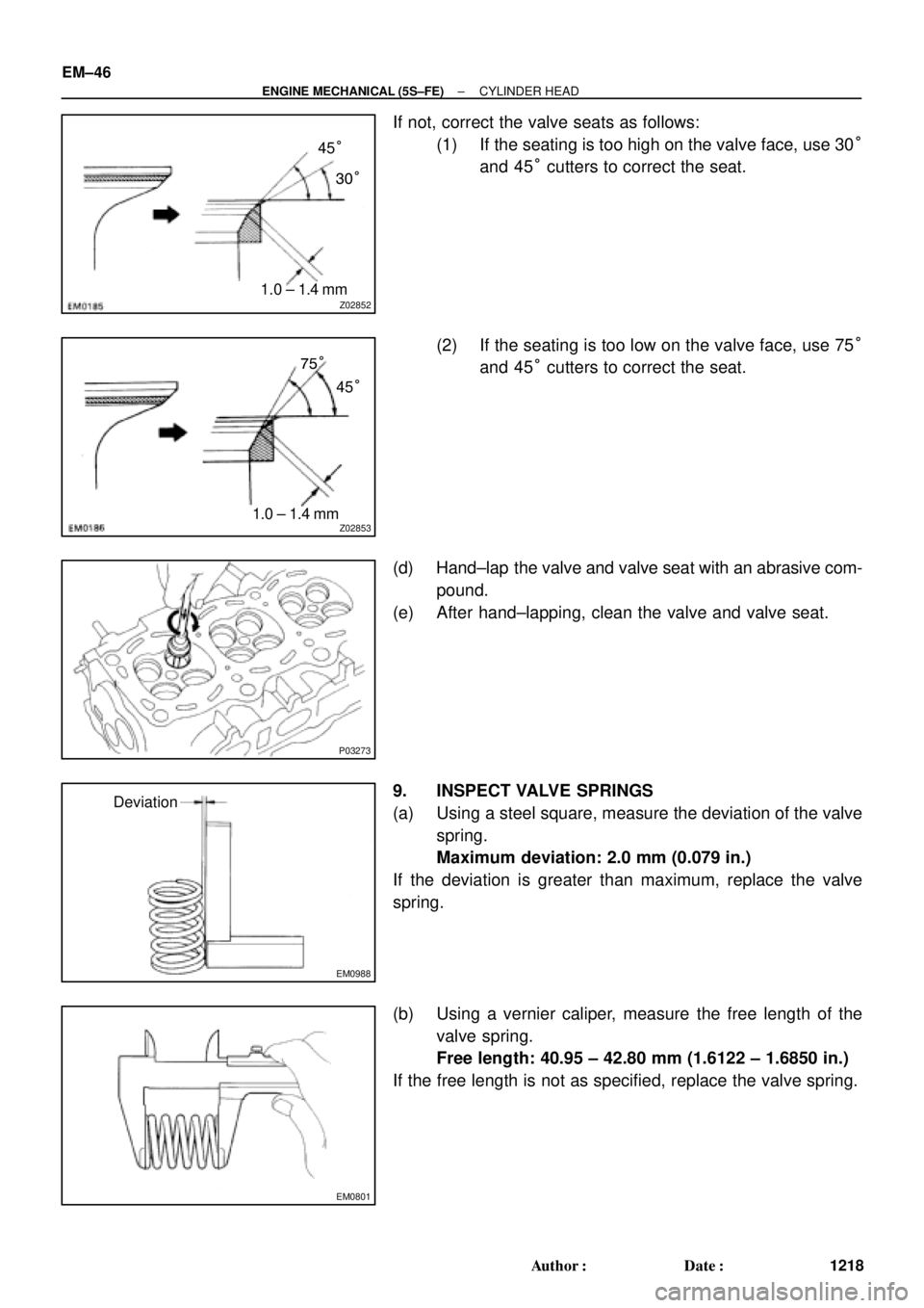
If not, correct the valve seats as follows:
(1) If the seating is too high on the valve face, use 30°
and 45° cutters to correct the seat.
(2) If the seating is too low on the valve face, use 75°
and 45° cutters to correct the seat.
(d) Hand±lap the valve and valve seat with an abrasive com-
pound.
(e) After hand±lapping, clean the valve and valve seat.
9. INSPECT VALVE SPRINGS
(a) Using a steel square, measure the deviation of the valve
spring.
Maximum deviation: 2.0 mm (0.079 in.)
If the deviation is greater than maximum, replace the valve
spring.
(b) Using a vernier caliper, measure the free length of the
valve spring.
Free length: 40.95 ± 42.80 mm (1.6122 ± 1.6850 in.)
If the free length is not as specified, replace the valve spring.
Page 2598 of 4592
CYLINDER HEAD
EM±47
1219 Author�: Date�:
(c) Using a spring tester, measure the tension of the valve
spring at the specif")
EM0281
EM1628
EM2011
EM2538
EM3322
Free Distance
± ENGINE MECHANICAL (5S±FE)CYLINDER HEAD
EM±47
1219 Author�: Date�:
(c) Using a spring tester, measure the tension of the valve
spring at the specified installed length.
Installed tension:
164 ± 189 N (16.7 ± 19.3 kgf, 36.8 ± 42.5 lbf)
at 34.7 mm (1.366 in.)
If the installed tension is not as specified, replace the valve
spring.
10. INSPECT CAMSHAFTS
(a) Inspect the circle runout.
(1) Place the camshaft on V±blocks.
(2) Using a dial indicator, measure the circle runout at
the center journal.
Maximum circle runout: 0.04 mm (0.0016 in.)
If the circle runout is greater than maximum, replace the cam-
shaft.
(b) Using a micrometer, measure the cam lobe height.
Standard cam lobe height:
Intake42.01 ± 42.11 mm (1.6539 ± 1.6579 in.)
Exhaust40.06 ± 40.16 mm (1.5772 ± 1.5811 in.)
Minimum cam lobe height:
Intake41.90 mm (1.6496 in.)
Exhaust39.95 mm (1.5728 in.)
If the cam lobe height is less than minimum, replace the cam-
shaft.
(c) Using a micrometer, measure the journal diameter.
Journal diameter:
26.959 ± 26.975 mm (1.0614 ± 1.0620 in.)
If the journal diameter is not as specified, check the oil clear-
ance.
(d) Using vernier calipers, measure the free distance be-
tween the gear spring ends.
Free distance: 22.5 ± 22.9 mm (0.886 ± 0.902 in.)
If the free distance is not as specified, replace the gear spring.