Page 970 of 4592
N10070
Full Belt Length Minus
200 mm (7.87 in.)
BO0633
15°
45°
± BODYSEAT BELT
BO±125
2473 Author�: Date�:
(e) Retract the whole belt, then pull out the belt until 200 mm
(7.87 in.) of belt remains retracted.
(f) Tilt the retractor slowly.
(g) Make sure that the belt can be pulled out at a tilt of 15 de-
grees or less, and cannot be pulled out at over 45 degrees
of tilt.
If a problem is found, replace the assembly.
Page 1013 of 4592
BO2E1±01
BO0632
BO0633
15°
45°
± BODYSEAT BELT
BO±27
INSPECTION
CAUTION:
Replace the seat belt assembly (Outer belt, inner belt,
bolts, nuts or sill±bar) if it has been used in a severe im-
pact. The entire assembly should be replaced even if dam-
age is not obvious.
1. All seat belt:
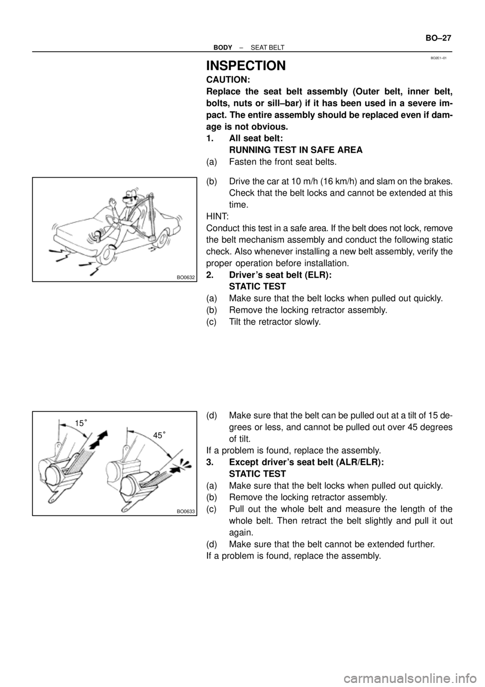
RUNNING TEST IN SAFE AREA
(a) Fasten the front seat belts.
(b) Drive the car at 10 m/h (16 km/h) and slam on the brakes.
Check that the belt locks and cannot be extended at this
time.
HINT:
Conduct this test in a safe area. If the belt does not lock, remove
the belt mechanism assembly and conduct the following static
check. Also whenever installing a new belt assembly, verify the
proper operation before installation.
2. Driver 's seat belt (ELR):
STATIC TEST
(a) Make sure that the belt locks when pulled out quickly.
(b) Remove the locking retractor assembly.
(c) Tilt the retractor slowly.
(d) Make sure that the belt can be pulled out at a tilt of 15 de-
grees or less, and cannot be pulled out over 45 degrees
of tilt.
If a problem is found, replace the assembly.
3. Except driver's seat belt (ALR/ELR):
STATIC TEST
(a) Make sure that the belt locks when pulled out quickly.
(b) Remove the locking retractor assembly.
(c) Pull out the whole belt and measure the length of the
whole belt. Then retract the belt slightly and pull it out
again.
(d) Make sure that the belt cannot be extended further.
If a problem is found, replace the assembly.
Page 1014 of 4592
N10070
Full Belt Length Minus
200 mm (7.87 in.)
BO0633
15°
45°
BO5906
BO±28
± BODYSEAT BELT
(e) Retract the whole belt, then pull out the belt until 200 mm
(7.87 in.) of belt remains retracted.
(f) Tilt the belt slowly.
(g) Make sure that the belt can be pulled out at a tilt of 15 de-
grees or less, and cannot be pulled out at over 45 degrees
of tilt.
If a problem is found, replace the assembly.
4. Manual type:
TESTING
(a) Adjust the belt to the proper length.
(b) Apply a firm load to the belt.
(c) Make sure that the belt is not extended.
Page 1030 of 4592
BR0AJ±02
BR±16
± BRAKEBRAKE MASTER CYLINDER
2039 Author�: Date�:
INSTALLATION
Installation is in the reverse order of removal (See page BR±11).
HINT:
�Before installation, adjust length of the brake booster push rod (See page BR±20).
�After installation, fill the brake reservoir with brake fluid, bleed the brake system and check for leaks
(See page BR±4).
�Check and adjust brake pedal (See page BR±5).
Page 1034 of 4592
BR0AN±03
F03521
SST
Gasket
R11347
SST BR±20
± BRAKEBRAKE BOOSTER ASSEMBLY
2043 Author�: Date�:
INSTALLATION
1. INSTALL BRAKE BOOSTER
(a) Install the booster and a new gasket.
(b) Install the clevis to the operating rod.
(c) Install and torque the booster installation nuts.
Torque: 13 N´m (130 kgf´cm, 9 ft´lbf)
(d) Install the clevis, and torque the lock nut.
Torque: 25 N´m (260 kgf´cm, 19 ft´lbf)
(e) Install the clevis pin into the clevis and brake pedal, and
install the clip to the clevis pin.
(f) Install the pedal return spring.
2. ADJUST LENGTH OF BOOSTER PUSH ROD
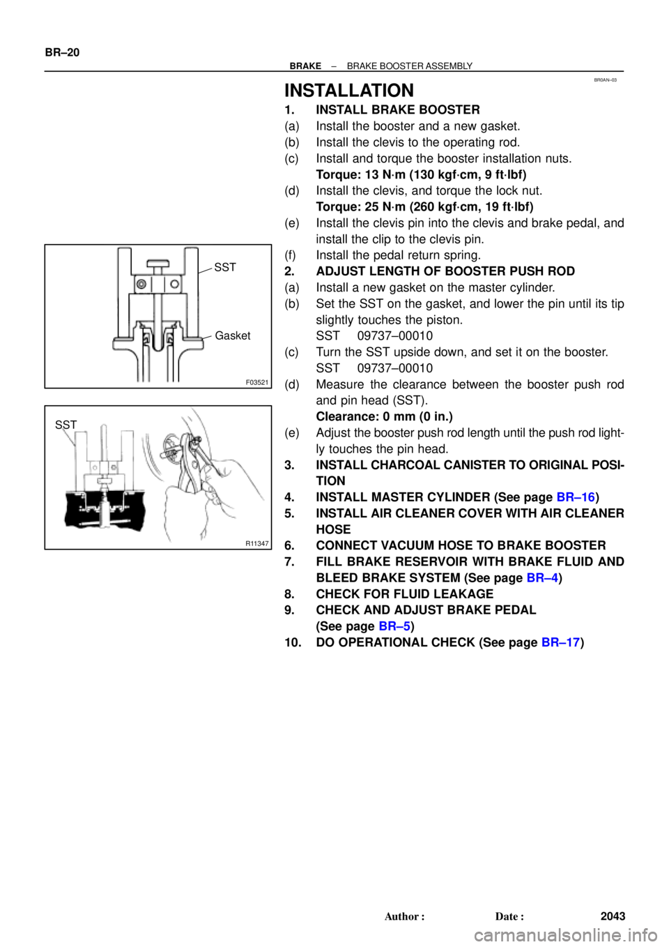
(a) Install a new gasket on the master cylinder.
(b) Set the SST on the gasket, and lower the pin until its tip
slightly touches the piston.
SST 09737±00010
(c) Turn the SST upside down, and set it on the booster.
SST 09737±00010
(d) Measure the clearance between the booster push rod
and pin head (SST).
Clearance: 0 mm (0 in.)
(e) Adjust the booster push rod length until the push rod light-
ly touches the pin head.
3. INSTALL CHARCOAL CANISTER TO ORIGINAL POSI-
TION
4. INSTALL MASTER CYLINDER (See page BR±16)
5. INSTALL AIR CLEANER COVER WITH AIR CLEANER
HOSE
6. CONNECT VACUUM HOSE TO BRAKE BOOSTER
7. FILL BRAKE RESERVOIR WITH BRAKE FLUID AND
BLEED BRAKE SYSTEM (See page BR±4)
8. CHECK FOR FLUID LEAKAGE
9. CHECK AND ADJUST BRAKE PEDAL
(See page BR±5)
10. DO OPERATIONAL CHECK (See page BR±17)
Page 1049 of 4592
BR0AZ±02
W01679
BR1553
F06423
± BRAKEREAR DRUM BRAKE
BR±35
2058 Author�: Date�:
INSTALLATION
Installation is in the reverse order of removal
(See page BR±32).
NOTICE:
Apply lithium soap base glycol grease and high tempera-
ture grease to the parts indicated by the arrows
(See page BR±31).
1. AFTER INSTALLATION, FILL BRAKE RESERVOIR
WITH BRAKE FLUID, BLEED BRAKE SYSTEM
(See page BR±4)
2. CHECK FOR LEAKS
3. CHECK OPERATION OF AUTOMATIC ADJUSTING
MECHANISM
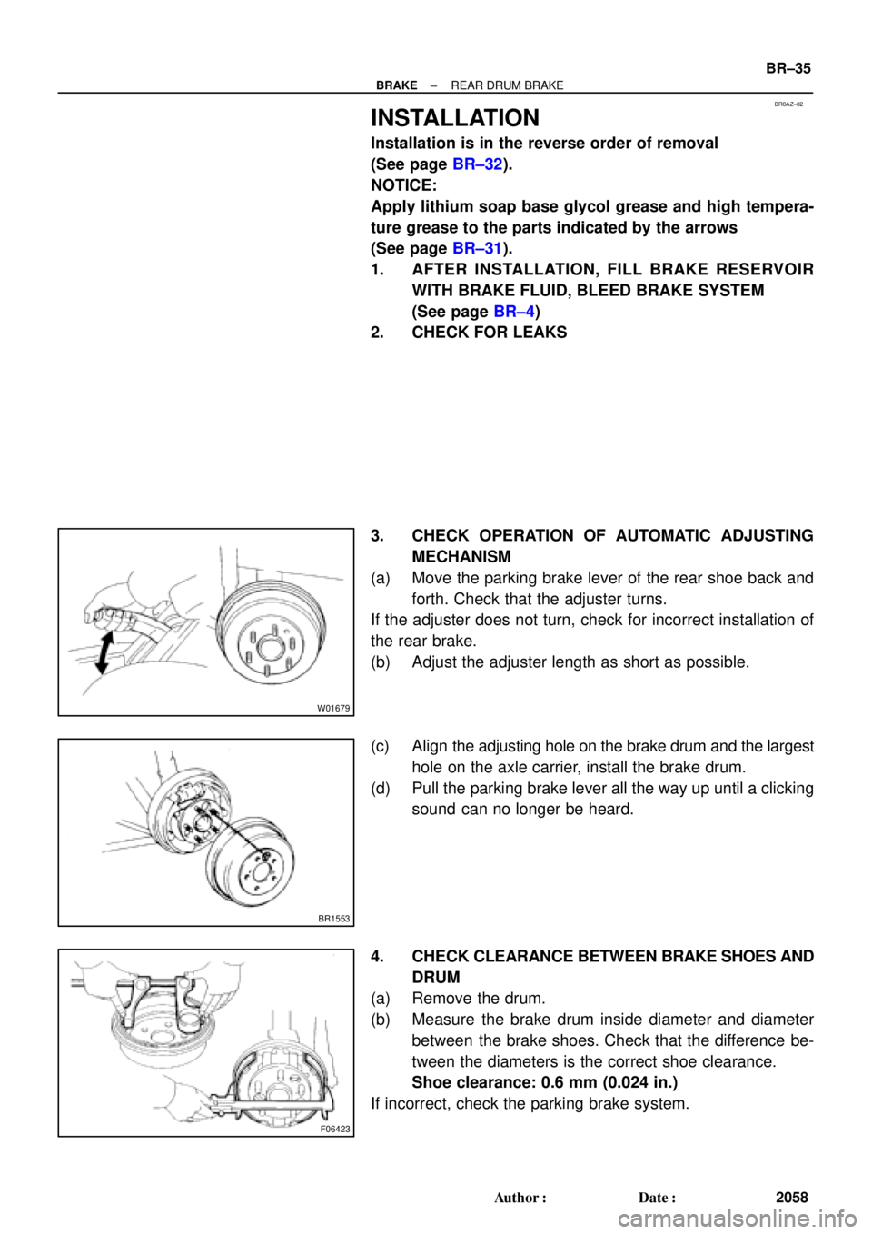
(a) Move the parking brake lever of the rear shoe back and
forth. Check that the adjuster turns.
If the adjuster does not turn, check for incorrect installation of
the rear brake.
(b) Adjust the adjuster length as short as possible.
(c) Align the adjusting hole on the brake drum and the largest
hole on the axle carrier, install the brake drum.
(d) Pull the parking brake lever all the way up until a clicking
sound can no longer be heard.
4. CHECK CLEARANCE BETWEEN BRAKE SHOES AND
DRUM
(a) Remove the drum.
(b) Measure the brake drum inside diameter and diameter
between the brake shoes. Check that the difference be-
tween the diameters is the correct shoe clearance.
Shoe clearance: 0.6 mm (0.024 in.)
If incorrect, check the parking brake system.
Page 1096 of 4592
P13535
Length
P13568
Ohmmeter
Positive (+)
Terminal
Rectifier
Terminal
P13566
Ohmmeter
Negative (±)
Terminal
CH±10
± CHARGING (5S±FE)GENERATOR
1757 Author�: Date�:
3. INSPECT BRUSHES
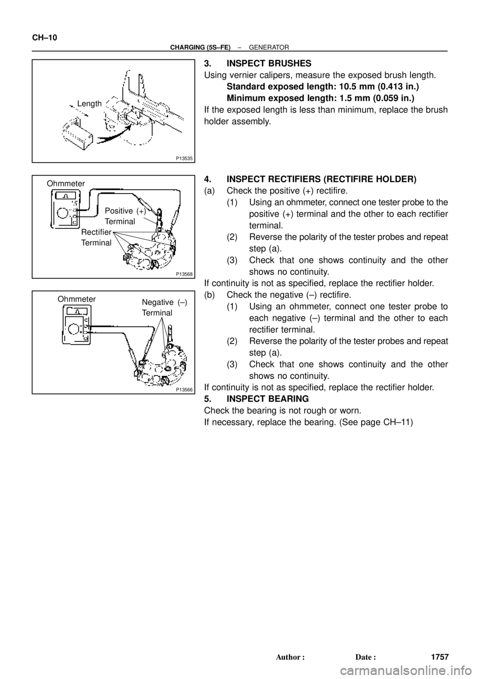
Using vernier calipers, measure the exposed brush length.
Standard exposed length: 10.5 mm (0.413 in.)
Minimum exposed length: 1.5 mm (0.059 in.)
If the exposed length is less than minimum, replace the brush
holder assembly.
4. INSPECT RECTIFIERS (RECTIFIRE HOLDER)
(a) Check the positive (+) rectifire.
(1) Using an ohmmeter, connect one tester probe to the
positive (+) terminal and the other to each rectifier
terminal.
(2) Reverse the polarity of the tester probes and repeat
step (a).
(3) Check that one shows continuity and the other
shows no continuity.
If continuity is not as specified, replace the rectifier holder.
(b) Check the negative (±) rectifire.
(1) Using an ohmmeter, connect one tester probe to
each negative (±) terminal and the other to each
rectifier terminal.
(2) Reverse the polarity of the tester probes and repeat
step (a).
(3) Check that one shows continuity and the other
shows no continuity.
If continuity is not as specified, replace the rectifier holder.
5. INSPECT BEARING
Check the bearing is not rough or worn.
If necessary, replace the bearing. (See page CH±11)
Page 1112 of 4592
P13535
Length
P00480
OhmmeterPositive (+)
Terminal
Rectifire
Terminal
P00481
OhmmeterNegative (±)
Treminal CH±10
± CHARGING (1MZ±FE)GENERATOR
1773 Author�: Date�:
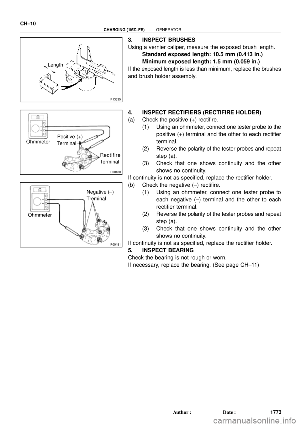
3. INSPECT BRUSHES
Using a vernier caliper, measure the exposed brush length.
Standard exposed length: 10.5 mm (0.413 in.)
Minimum exposed length: 1.5 mm (0.059 in.)
If the exposed length is less than minimum, replace the brushes
and brush holder assembly.
4. INSPECT RECTIFIERS (RECTIFIRE HOLDER)
(a) Check the positive (+) rectifire.
(1) Using an ohmmeter, connect one tester probe to the
positive (+) terminal and the other to each rectifier
terminal.
(2) Reverse the polarity of the tester probes and repeat
step (a).
(3) Check that one shows continuity and the other
shows no continuity.
If continuity is not as specified, replace the rectifier holder.
(b) Check the negative (±) rectifire.
(1) Using an ohmmeter, connect one tester probe to
each negative (±) terminal and the other to each
rectifier terminal.
(2) Reverse the polarity of the tester probes and repeat
step (a).
(3) Check that one shows continuity and the other
shows no continuity.
If continuity is not as specified, replace the rectifier holder.
5. INSPECT BEARING
Check the bearing is not rough or worn.
If necessary, replace the bearing. (See page CH±11)