Page 73 of 2267
Wiring Diagram Ð AT Ð TCVNCAT0207
M48
GY/R GY/RF102
GY/R
M48
F71
AT-TCV-01
M53
5
15 16 17 1918620414313212721822923W 3
21LU
DUTY SOL
9
11110
24
W
3 2 1 45678
910 11 12 13 14 15 16 17 18
19 20 21 22 23 24
F71 GY/R
F10254
96 2
7 3
81
G10
YAT149
TCM
(TRANSMISSION
CONTROL
MODULE)
: Detectable line for DTC
: Non-detectable line for DTC
CONTROL VALVE
(TORQUE
CONVERTER
CLUTCH
SOLENOID VALVE)
DTC P0740 TORQUE CONVERTER CLUTCH SOLENOID VALVE
Wiring Diagram Ð AT Ð TCV
AT-71
Page 78 of 2267
Wiring Diagram Ð AT Ð LPSVNCAT0209
OR/L P/B
OR/L P/B
OR/L P/B
P/B
OR/L22 20M53
M48
OR/L
M48
F86F102F71
AT-LPSV-01
515 16 17 1918620414313212721822923W 1 PL DUTY
SOL
8 2
2
1F86
11110
24
PL DUTY
SOL (DR)
W
3 2 1 45678
910 11 12 13 14 15 16 17 18
19 20 21 22 23 24
F71
F102
2 1
GY54
96 2
7 3
81
G10
YAT150
TCM
(TRANSMISSION
CONTROL
MODULE)
: Detectable line for DTC
: Non-detectable line for DTC
DROPPING
RESISTOR
CONTROL VALVE
(LINE PRESSURE
SOLENOID VALVE)
DTC P0745 LINE PRESSURE SOLENOID VALVE
Wiring Diagram Ð AT Ð LPSV
AT-76
Page 90 of 2267
Wiring Diagram Ð AT Ð STMNCAT0225
YAT208
TCM
(TRANSMISSION
CONTROL MODULE)
: Detectable line for DTC
: Non-detectable line for DTC
CONTROL
VA LV E
(STEP MOTOR)
DTC P1777 STEP MOTOR Ð CIRCUIT
Wiring Diagram Ð AT Ð STM
AT-88
Page 98 of 2267
Wiring Diagram Ð AT Ð FPSNCAT0233
YAT209
TCM
(TRANSMISSION
CONTROL MODULE): Detectable line for DTC
: Non-detectable line for DTC CONTROL VALVE
(CVT FLUID
PRESSURE
SENSOR)ECM
DTC P1791 CVT FLUID PRESSURE SENSOR
Wiring Diagram Ð AT Ð FPS
AT-96
Page 107 of 2267
PNP Switch, Stop Lamp Switch and Throttle
Position Switch
NAAT0204
SYMPTOM:
CVT or SPORT indicator lamp does not come on in TCM self-
diagnostic procedure even the lamp circuit is good.
DESCRIPTIONNAT0204S01
IPNP switch
IThe PNP switch assemble includes a transmission range
switch. The transmission range switch detects the selector
position and sends a signal to the TCM.
IStop lamp switch
Detects the stop lamp switch position (ON or OFF) and sends
a signal to the TCM
IThrottle position switch.
Consists of a wide open throttle position switch and a closed
throttle position switch.
The wide open throttle position switch sends a signal to the
TCM when the throttle valve is open at least 1/2 of the full
throttle position. The closed throttle position switch sends a
signal to the TCM when the throttle valve is fully closed.
TROUBLE DIAGNOSES FOR NON-DETECTABLE ITEMS
PNP Switch, Stop Lamp Switch and Throttle Position Switch
AT-105
Page 112 of 2267
Wiring Diagram Ð AT Ð NONDTC
MODELS BEFORE VIN - P11U0548750NCAT0237
YAT155
BATTERYIGNITION SWITCH
ON or START
FUSE
BLOCK
(J/B)Refer to
EL-POWER.TCM
(TRANSMISSION
CONTROL MODULE)
Detectable line for DTC
Non-detectable line for DTC
Hyper CVT models
Hyper CVT M6 models
SPORT indicator lamp
CVT warning lamp
UNIFIED METER CONTROL UNITCOMBINATION
METER
INDICATOR
CONTROL
UNIT
REFER TO THE FOLLOWING
FUSE BLOCK - Junction Box (J/B)
TROUBLE DIAGNOSES FOR NON-DETECTABLE ITEMS
Wiring Diagram Ð AT Ð NONDTC
AT-110
Page 184 of 2267
Wiring Diagram Ð ABS Ð
MODELS WITH SELF-DIAGNOSIS FUNCTION
YBR208 BATTERYIGNITION SWITCH
ON or START
FUSE
BLOCK
(J/B)Refer to EL-POWER.
: LHD models
: RHD models: CVT models
: M/T models
RELEASEDDEPRESSEDSTOP LAMP
SWITCH
FUSE
BLOCK
(J/B)COMBINATION METER
(ABS WARNING LAMP)
ABS ACTUATOR
AND ELECTRIC
UNIT
(CONTROL UNIT)
TCM
(TRANSMISSION CON-
TROL MODULE)DATA LINK CON-
NECTOR
Refer to las page (Foldout page).
TROUBLE DIAGNOSES
BR-62
Page 475 of 2267

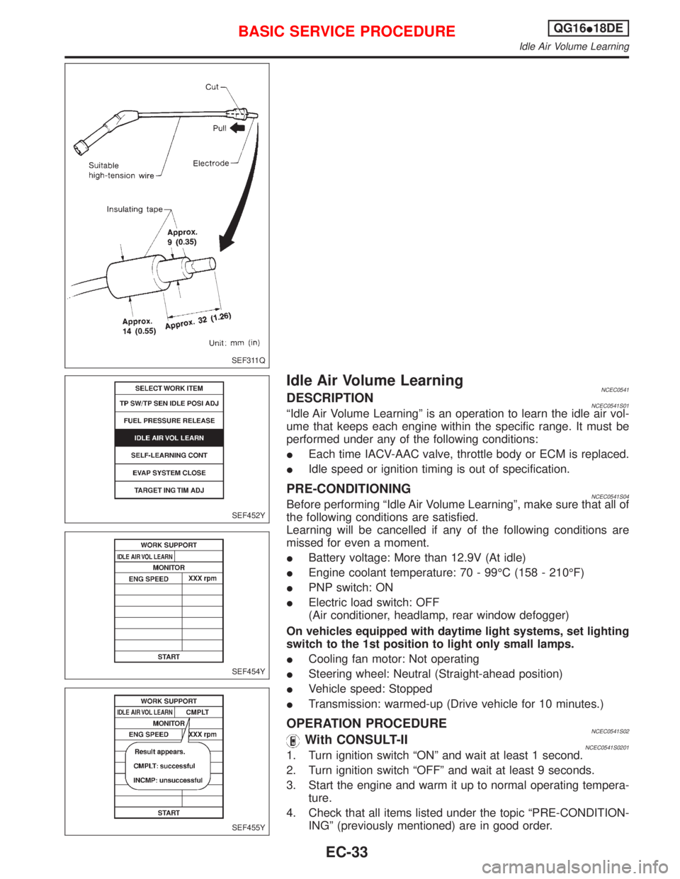
Idle Air Volume LearningNCEC0541DESCRIPTIONNCEC0541S01ªIdle Air Volume Learningº is an operation to learn the idle air vol-
ume that keeps each engine within the specific range. It must be
performed under any of the following conditions:
IEach time IACV-AAC valve, throttle body or ECM is replaced.
IIdle speed or ignition timing is out of specification.
PRE-CONDITIONINGNCEC0541S04Before performing ªIdle Air Volume Learningº, make sure that all of
the following conditions are satisfied.
Learning will be cancelled if any of the following conditions are
missed for even a moment.
IBattery voltage: More than 12.9V (At idle)
IEngine coolant temperature: 70 - 99ÉC (158 - 210ÉF)
IPNP switch: ON
IElectric load switch: OFF
(Air conditioner, headlamp, rear window defogger)
On vehicles equipped with daytime light systems, set lighting
switch to the 1st position to light only small lamps.
ICooling fan motor: Not operating
ISteering wheel: Neutral (Straight-ahead position)
IVehicle speed: Stopped
ITransmission: warmed-up (Drive vehicle for 10 minutes.)
OPERATION PROCEDURENCEC0541S02With CONSULT-IINCEC0541S02011. Turn ignition switch ªONº and wait at least 1 second.
2. Turn ignition switch ªOFFº and wait at least 9 seconds.
3. Start the engine and warm it up to normal operating tempera-
ture.
4. Check that all items listed under the topic ªPRE-CONDITION-
INGº (previously mentioned) are in good order.
SEF311Q
SEF452Y
SEF454Y
SEF455Y
BASIC SERVICE PROCEDUREQG16I18DE
Idle Air Volume Learning
EC-33