Page 1093 of 2267
Diagnostic ProcedureNCEC0332
1 RETIGHTEN GROUND SCREWS
1. Turn ignition switch ªOFFº.
2. Loosen and retighten engine ground screws.
©GO TO 2.
2 CHECK INPUT SIGNAL CIRCUIT
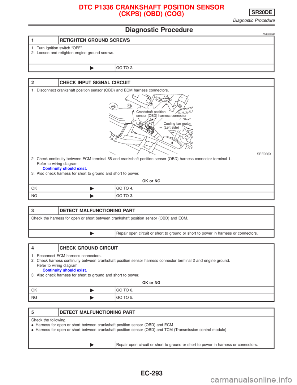
1. Disconnect crankshaft position sensor (OBD) and ECM harness connectors.
SEF226X2. Check continuity between ECM terminal 65 and crankshaft position sensor (OBD) harness connector terminal 1.
Refer to wiring diagram.
Continuity should exist.
3. Also check harness for short to ground and short to power.
OK or NG
OK©GO TO 4.
NG©GO TO 3.
3 DETECT MALFUNCTIONING PART
Check the harness for open or short between crankshaft position sensor (OBD) and ECM.
©Repair open circuit or short to ground or short to power in harness or connectors.
4 CHECK GROUND CIRCUIT
1. Reconnect ECM harness connectors.
2. Check harness continuity between crankshaft position sensor harness connector terminal 2 and engine ground.
Refer to wiring diagram.
Continuity should exist.
3. Also check harness for short to ground and short to power.
OK or NG
OK©GO TO 6.
NG©GO TO 5.
5 DETECT MALFUNCTIONING PART
Check the following.
IHarness for open or short between crankshaft position sensor (OBD) and ECM
IHarness for open or short between crankshaft position sensor (OBD) and TCM (Transmission control module)
©Repair open circuit or short to ground or short to power in harness or connectors.
Crankshaft position
sensor (OBD) harness connector
Cooling fan motor
(Left side)
DTC P1336 CRANKSHAFT POSITION SENSOR
(CKPS) (OBD) (COG)SR20DE
Diagnostic Procedure
EC-293
Page 1095 of 2267
System DescriptionNCEC0560The malfunction information related to CVT is transferred through the line (circuit) from TCM (Transmission
Control Module) to ECM. Therefore, be sure to erase the malfunction information such as DTC not only in TCM
(Transmission Control Module) but also ECM after the CVT related repair.
ECM Terminals and Reference ValueNCEC0561Specification data are reference values and are measured between each terminal and 48 (ECM ground).
TER-
MINAL
NO.WIRE
COLORITEM CONDITION DATA (DC Voltage)
91 PU/Y CVT check signal[Ignition switch ªONº]
[Engine is running]0 - Approximately 5V
On Board Diagnosis LogicNCEC0562
DTC No. Malfunction is detected when ... Check Items (Possible Cause)
P1605
1605IAn incorrect signal from TCM (Transmission Control
Module) is sent to ECM.IHarness or connectors
[The communication line circuit between ECM and
TCM (Transmission Control Module) is open or
shorted.]
IDead (Weak) battery
ITCM (Transmission Control Module)
DTC Confirmation ProcedureNCEC0563NOTE:
If ªDTC CONFIRMATION PROCEDUREº has been previously
conducted, always turn ignition switch ªOFFº and wait at least 9
seconds before conducting the next test.
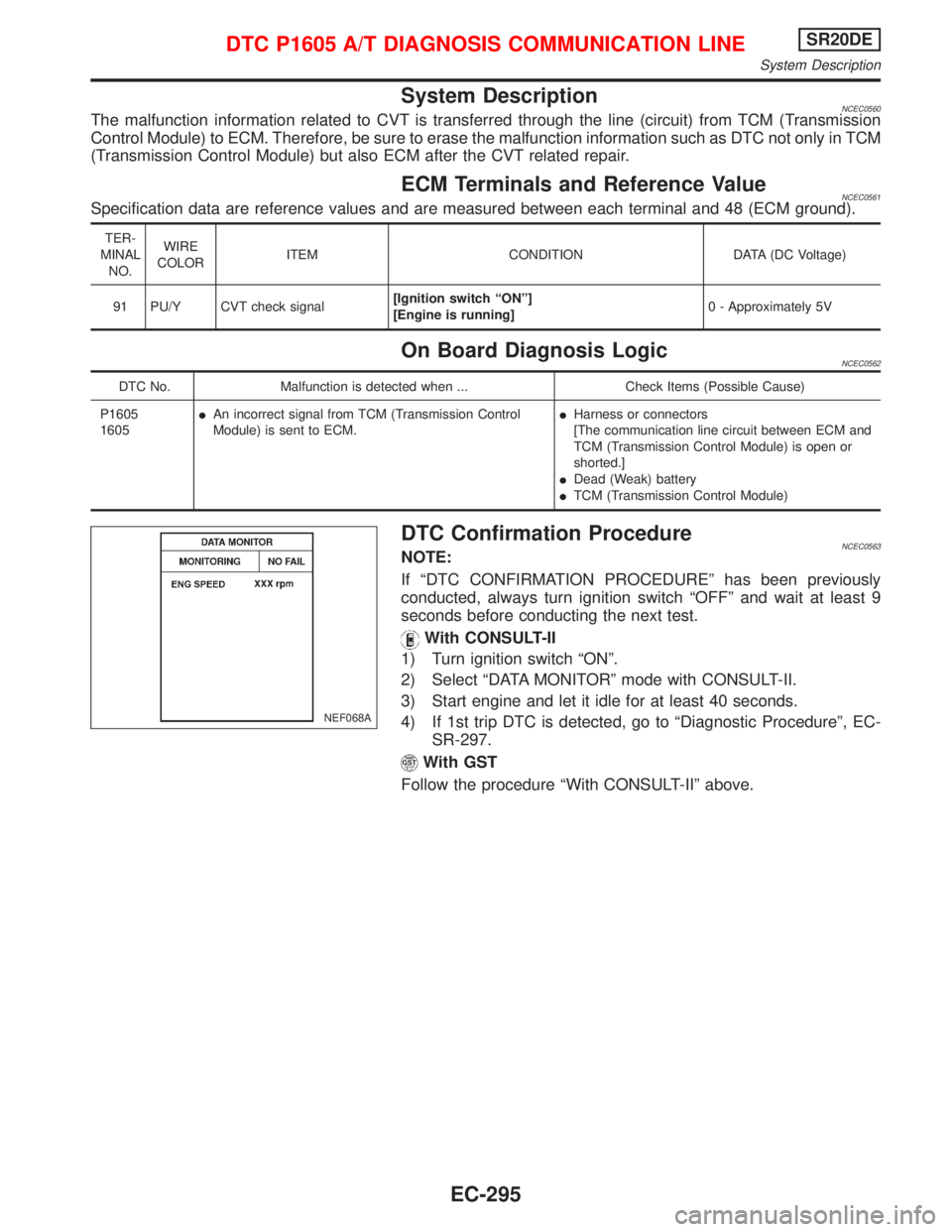
With CONSULT-II
1) Turn ignition switch ªONº.
2) Select ªDATA MONITORº mode with CONSULT-II.
3) Start engine and let it idle for at least 40 seconds.
4) If 1st trip DTC is detected, go to ªDiagnostic Procedureº, EC-
SR-297.
With GST
Follow the procedure ªWith CONSULT-IIº above.
NEF068A
DTC P1605 A/T DIAGNOSIS COMMUNICATION LINESR20DE
System Description
EC-295
Page 1096 of 2267
Wiring DiagramNCEC0564
YEC850
: Detectable line for DTC
: Non-detectable line for DTC TCM
(TRANSMISSION
CONTROL
MODULE)
ECM
F101
.ATCK
DTC P1605 A/T DIAGNOSIS COMMUNICATION LINESR20DE
Wiring Diagram
EC-296
Page 1157 of 2267
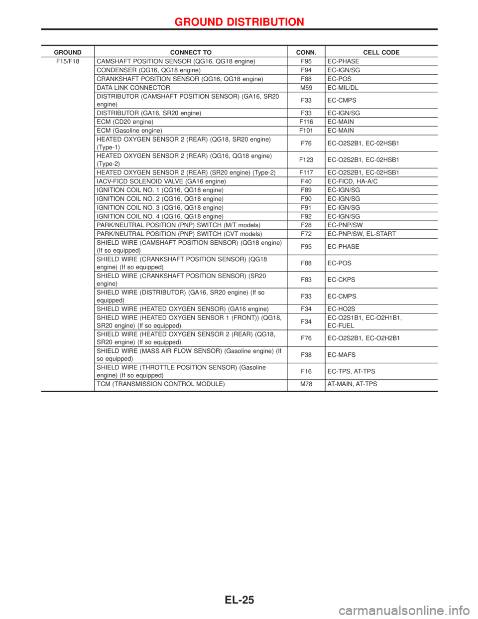
GROUND CONNECT TO CONN. CELL CODE
F15/F18 CAMSHAFT POSITION SENSOR (QG16, QG18 engine) F95 EC-PHASE
CONDENSER (QG16, QG18 engine) F94 EC-IGN/SG
CRANKSHAFT POSITION SENSOR (QG16, QG18 engine) F88 EC-POS
DATA LINK CONNECTOR M59 EC-MIL/DL
DISTRIBUTOR (CAMSHAFT POSITION SENSOR) (GA16, SR20
engine)F33 EC-CMPS
DISTRIBUTOR (GA16, SR20 engine) F33 EC-IGN/SG
ECM (CD20 engine) F116 EC-MAIN
ECM (Gasoline engine) F101 EC-MAIN
HEATED OXYGEN SENSOR 2 (REAR) (QG18, SR20 engine)
(Type-1)F76 EC-O2S2B1, EC-02HSB1
HEATED OXYGEN SENSOR 2 (REAR) (QG16, QG18 engine)
(Type-2)F123 EC-O2S2B1, EC-02HSB1
HEATED OXYGEN SENSOR 2 (REAR) (SR20 engine) (Type-2) F117 EC-O2S2B1, EC-02HSB1
IACV-FICD SOLENOID VALVE (GA16 engine) F40 EC-FICD, HA-A/C
IGNITION COIL NO. 1 (QG16, QG18 engine) F89 EC-IGN/SG
IGNITION COIL NO. 2 (QG16, QG18 engine) F90 EC-IGN/SG
IGNITION COIL NO. 3 (QG16, QG18 engine) F91 EC-IGN/SG
IGNITION COIL NO. 4 (QG16, QG18 engine) F92 EC-IGN/SG
PARK/NEUTRAL POSITION (PNP) SWITCH (M/T models) F28 EC-PNP/SW
PARK/NEUTRAL POSITION (PNP) SWITCH (CVT models) F72 EC-PNP/SW, EL-START
SHIELD WIRE (CAMSHAFT POSITION SENSOR) (QG18 engine)
(If so equipped)F95 EC-PHASE
SHIELD WIRE (CRANKSHAFT POSITION SENSOR) (QG18
engine) (If so equipped)F88 EC-POS
SHIELD WIRE (CRANKSHAFT POSITION SENSOR) (SR20
engine)F83 EC-CKPS
SHIELD WIRE (DISTRIBUTOR) (GA16, SR20 engine) (If so
equipped)F33 EC-CMPS
SHIELD WIRE (HEATED OXYGEN SENSOR) (GA16 engine) F34 EC-HO2S
SHIELD WIRE (HEATED OXYGEN SENSOR 1 (FRONT)) (QG18,
SR20 engine) (If so equipped)F34EC-O2S1B1, EC-O2H1B1,
EC-FUEL
SHIELD WIRE (HEATED OXYGEN SENSOR 2 (REAR) (QG18,
SR20 engine) (If so equipped)F76 EC-O2S2B1, EC-O2H2B1
SHIELD WIRE (MASS AIR FLOW SENSOR) (Gasoline engine) (If
so equipped)F38 EC-MAFS
SHIELD WIRE (THROTTLE POSITION SENSOR) (Gasoline
engine) (If so equipped)F16 EC-TPS, AT-TPS
TCM (TRANSMISSION CONTROL MODULE) M78 AT-MAIN, AT-TPS
GROUND DISTRIBUTION
EL-25
Page 1288 of 2267
INSPECTION/VEHICLE SPEED SENSOR
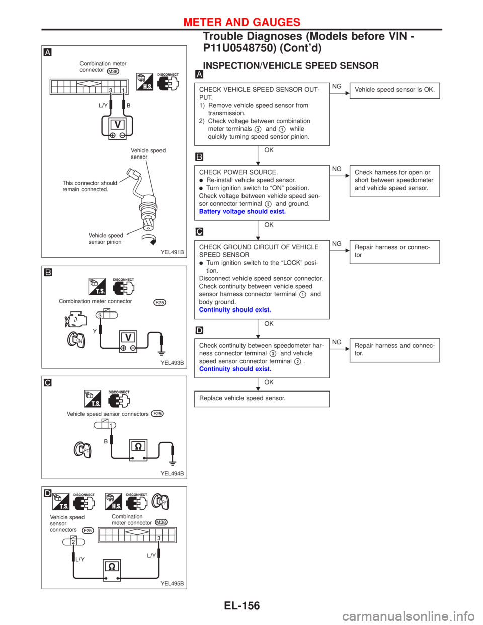
CHECK VEHICLE SPEED SENSOR OUT-
PUT.
1) Remove vehicle speed sensor from
transmission.
2) Check voltage between combination
meter terminals
�3and�1while
quickly turning speed sensor pinion.
OK
�NG
Vehicle speed sensor is OK.
CHECK POWER SOURCE.�Re-install vehicle speed sensor.�Turn ignition switch to“ON”position.
Check voltage between vehicle speed sen-
sor connector terminal
�3and ground.
Battery voltage should exist.
OK
�NG
Check harness for open or
short between speedometer
and vehicle speed sensor.
CHECK GROUND CIRCUIT OF VEHICLE
SPEED SENSOR
�Turn ignition switch to the“LOCK”posi-
tion.
Disconnect vehicle speed sensor connector.
Check continuity between vehicle speed
sensor harness connector terminal
�1and
body ground.
Continuity should exist.
OK
�NG
Repair harness or connec-
tor
Check continuity between speedometer har-
ness connector terminal
�3and vehicle
speed sensor connector terminal
�2.
Continuity should exist.
OK
�NG
Repair harness and connec-
tor.
Replace vehicle speed sensor.
YEL491B
Combination meter
connector
Vehicle speed
sensor
This connector should
remain connected.
Vehicle speed
sensor pinion
YEL493B
Combination meter connector
YEL494B
Vehicle speed sensor connectors
YEL495B
Vehicle speed
sensor
connectorsCombination
meter connector
�
�
�
�
METER AND GAUGES
Trouble Diagnoses (Models before VIN -
P11U0548750) (Cont’d)
EL-156
Page 1292 of 2267
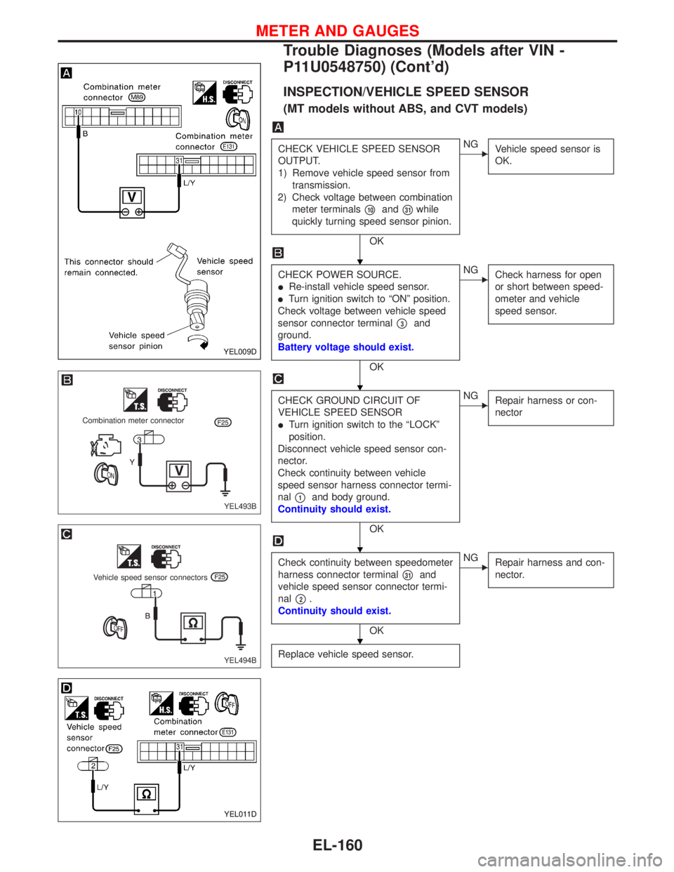
INSPECTION/VEHICLE SPEED SENSOR
(MT models without ABS, and CVT models)
CHECK VEHICLE SPEED SENSOR
OUTPUT.
1) Remove vehicle speed sensor from
transmission.
2) Check voltage between combination
meter terminals
�10and�31while
quickly turning speed sensor pinion.
OK
�NG
Vehicle speed sensor is
OK.
CHECK POWER SOURCE.
�Re-install vehicle speed sensor.
�Turn ignition switch to“ON”position.
Check voltage between vehicle speed
sensor connector terminal
�3and
ground.
Battery voltage should exist.
OK
�NG
Check harness for open
or short between speed-
ometer and vehicle
speed sensor.
CHECK GROUND CIRCUIT OF
VEHICLE SPEED SENSOR
�Turn ignition switch to the“LOCK”
position.
Disconnect vehicle speed sensor con-
nector.
Check continuity between vehicle
speed sensor harness connector termi-
nal
�1and body ground.
Continuity should exist.
OK
�NG
Repair harness or con-
nector
Check continuity between speedometer
harness connector terminal
�31and
vehicle speed sensor connector termi-
nal
�2.
Continuity should exist.
OK
�NG
Repair harness and con-
nector.
Replace vehicle speed sensor.
YEL009D
YEL493B
Combination meter connector
YEL494B
Vehicle speed sensor connectors
YEL011D
�
�
�
�
METER AND GAUGES
Trouble Diagnoses (Models after VIN -
P11U0548750) (Cont’d)
EL-160
Page 1498 of 2267
Passenger Compartment
LHD MODELS
YEL235C Time control unit
Blower
relay
Circuit
breaker-1Indicator control unit
Stop lamp switchNATS IMMU
Auto level control unit
Headlamp washer timer
Ignition
relay
Circuit breaker-2
Theft warning horn relay
Fuse block (J/B)
Rear window defogger relayAir bag diagnosis sensor unit
TCM (Transmission control module)Daytime light control unit
Fuse block (J/B)
Time control unt
Power window relay
Front fog lamp relay
Fuel pump relayA/C LOW relay, A/C MED-LOW relay, A/C MED-HIGH relay, A/C HIGH relayECM
LOCATION OF ELECTRICAL UNITS
EL-366
Page 1499 of 2267
RHD MODELS
YEL236C NATS IMMU
Auto level control unitHeadlamp washer timer
Stop lamp switch
A/C LOW relay. A/C MED-LOW relay. A/C MED-HIGH relay. A/C HIGH relayFuse block (J/B)
Power window relay Air bag diagnosis sensor unit
ECM
Front fog lamp relay TCM (Transmission control module)
Fuel pump relay Indicator control unit
Time control unit
Fuse block (J/B)
Time control unit
Ignition
relay
Circuit
breaker-1
Blower relay
Circuit breaker-2
Theft warning horn relay
Rear window defogger relay
LOCATION OF ELECTRICAL UNITS
Passenger Compartment (Cont’d)
EL-367