Page 2114 of 2267
Case Components
REMOVAL AND INSTALLATION
Input shaft oil seal
IApply multi-purpose grease to seal lip of oil seal before
installing.
Input shaft rear bearing
1. Remove welch plug from transmission case.
2. Remove input shaft rear bearing by tapping it from welch plug
hole.
3. Install welch plug.
IApply recommended sealant to mating surface of trans-
mission case.
SMT660A Drift
SMT751BA KV38102100
SMT705B
SMT704B
SMT705B
REPAIR FOR COMPONENT PARTSRS5F32A
Case Components
MT-37
Page 2116 of 2267
Differential Side Bearing Preload
If any of the following parts are replaced, adjust differential side
bearing preload.
IDifferential case
IDifferential side bearing
IClutch housing
ITransmission case
1. Remove differential side bearing outer race (transmission case
side) and shim.
2. Reinstall differential side bearing outer race without shim.
3. Install final drive assembly on clutch housing.
4. Install transmission case on clutch housing.
ITighten transmission case fixing bolts to the specified
torque.
5. Set dial indicator on front end of differential case.
6. Insert Tool all the way into differential side gear.
7. Move Tool up and down and measure dial indicator deflection.
8. Select shim of proper thickness using SDS table as a guide.
Differential side bearing adjusting shims:
Refer to SDS MT-88.
SMT645 ST33290001
SMT646A
SMT454 KV38106000
KV38107700
ADJUSTMENTRS5F32A
Differential Side Bearing Preload
MT-39
Page 2117 of 2267
9. Install selected shim and differential side bearing outer race.
10. Check differential side bearing turning torque.
a. Install final drive assembly on clutch housing.
b. Install transmission case on clutch housing.
ITighten transmission case fixing bolts to the specified
torque. Page MT-15
c. Measure turning torque of final drive assembly.
Turning torque of final drive assembly
(New bearing):
2.9 - 6.9 N´m (30 - 70 kg-cm, 26 - 61 in-lb)
IWhen old bearing is used again, turning torque will be
slightly less than the above.
IMake sure torque is close to the specified range.
IChanges in turning torque of final drive assembly per
revolution should be within 1.0 N´m (10 kg-cm, 8.7 in-lb)
without binding.
SMT600 KV38107700
ADJUSTMENTRS5F32A
Differential Side Bearing Preload (Cont'd)
MT-40
Page 2120 of 2267
13. Apply recommended sealant to mating surface of clutch hous-
ing.
14. Install transmission case on clutch housing.
15. Install mainshaft front bearing snap ring.
16. Tap mainshaft with a soft hammer to ensure mainshaft rear
bearing snap ring contacts the surface of transmission case.
SMT587 Apply sealant
continuously
SMT666B
SMT665B Snap ring
SMT758B
ASSEMBLYRS5F32A
MT-43
Page 2121 of 2267
17. Select case cover using the following procedure.
a. Measure distance between case cover fitting surface and
mainshaft rear bearing outer race.
Clearance ªCº between the end of case cover and
main shaft rear bearing outer race (Main shaft end
play):
0 - 0.1 mm (0 - 0.004 in)
b. Select case cover so that clearance ªCº will be specified clear-
ance.
Case cover:
Refer to SDS MT-89.
18. Install O-ring and case cover on transmission case.
IApply recommended sealant to mating surface of trans-
mission case.
SMT775B Case cover
Thickness of cover
End
play
SMT664B Case cover
ASSEMBLYRS5F32A
MT-44
Page 2125 of 2267

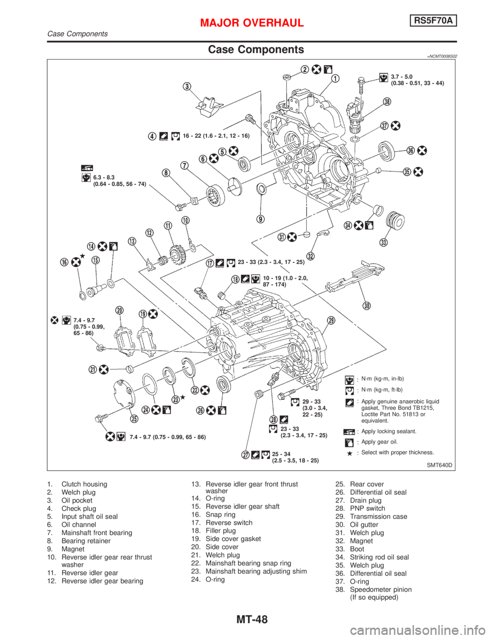
Case Components=NCMT0008S02
1. Clutch housing
2. Welch plug
3. Oil pocket
4. Check plug
5. Input shaft oil seal
6. Oil channel
7. Mainshaft front bearing
8. Bearing retainer
9. Magnet
10. Reverse idler gear rear thrust
washer
11. Reverse idler gear
12. Reverse idler gear bearing13. Reverse idler gear front thrust
washer
14. O-ring
15. Reverse idler gear shaft
16. Snap ring
17. Reverse switch
18. Filler plug
19. Side cover gasket
20. Side cover
21. Welch plug
22. Mainshaft bearing snap ring
23. Mainshaft bearing adjusting shim
24. O-ring25. Rear cover
26. Differential oil seal
27. Drain plug
28. PNP switch
29. Transmission case
30. Oil gutter
31. Welch plug
32. Magnet
33. Boot
34. Striking rod oil seal
35. Welch plug
36. Differential oil seal
37. O-ring
38. Speedometer pinion
(If so equipped)
SMT640D 16 - 22 (1.6 - 2.1, 12 - 16)
6.3 - 8.3
(0.64 - 0.85, 56 - 74)
7.4 - 9.7
(0.75 - 0.99,
65 - 86)
7.4 - 9.7 (0.75 - 0.99, 65 - 86)23 - 33 (2.3 - 3.4, 17 - 25)
10 - 19 (1.0 - 2.0,
87 - 174)3.7 - 5.0
(0.38 - 0.51, 33 - 44)
29-33
(3.0 - 3.4,
22 - 25)
23-33
(2.3 - 3.4, 17 - 25)
25-34
(2.5 - 3.5, 18 - 25)N´m (kg-m, in-lb)
N´m (kg-m, ft-lb)
Apply genuine anaerobic liquid
gasket, Three Bond TB1215,
Loctite Part No. 51813 or
equivalent.
Apply locking sealant.
Apply gear oil.
Select with proper thickness.
MAJOR OVERHAULRS5F70A
Case Components
MT-48
Page 2179 of 2267

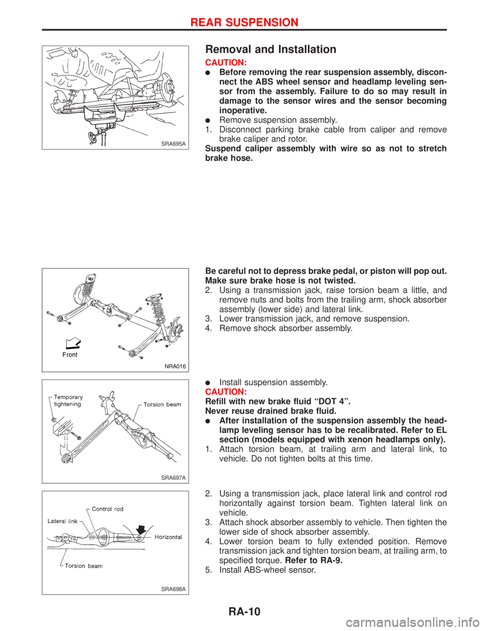
Removal and Installation
CAUTION:
lBefore removing the rear suspension assembly, discon-
nect the ABS wheel sensor and headlamp leveling sen-
sor from the assembly. Failure to do so may result in
damage to the sensor wires and the sensor becoming
inoperative.
lRemove suspension assembly.
1. Disconnect parking brake cable from caliper and remove
brake caliper and rotor.
Suspend caliper assembly with wire so as not to stretch
brake hose.
Be careful not to depress brake pedal, or piston will pop out.
Make sure brake hose is not twisted.
2. Using a transmission jack, raise torsion beam a little, and
remove nuts and bolts from the trailing arm, shock absorber
assembly (lower side) and lateral link.
3. Lower transmission jack, and remove suspension.
4. Remove shock absorber assembly.
lInstall suspension assembly.
CAUTION:
Refill with new brake fluid ªDOT 4º.
Never reuse drained brake fluid.
lAfter installation of the suspension assembly the head-
lamp leveling sensor has to be recalibrated. Refer to EL
section (models equipped with xenon headlamps only).
1. Attach torsion beam, at trailing arm and lateral link, to
vehicle. Do not tighten bolts at this time.
2. Using a transmission jack, place lateral link and control rod
horizontally against torsion beam. Tighten lateral link on
vehicle.
3. Attach shock absorber assembly to vehicle. Then tighten the
lower side of shock absorber assembly.
4. Lower torsion beam to fully extended position. Remove
transmission jack and tighten torsion beam, at trailing arm, to
specified torque.Refer to RA-9.
5. Install ABS-wheel sensor.
SRA695A
NRA016
SRA697A
SRA698A
REAR SUSPENSION
RA-10
Page 2245 of 2267

Precautions
Supplemental Restraint System (SRS) ªAIR BAGº
and ªSEAT BELT PRE-TENSIONERº
The Supplemental Restraint System ªAir Bagº and ªSeat Belt Pre-tensionerº, used along with a seat belt,
help to reduce the risk or severity of injury to the driver and front passenger in a frontal collision. The
Supplemental Restraint System consists of air bag modules (located in the center of the steering wheel and
on the instrument panel on the passenger side), seat belt pre-tensioners, a diagnosis sensor unit, warning
lamp, wiring harness and spiral cable.
If the vehicle is equipped with side air bag as the Supplemental Restraint System, the side air bag used along
with the seat belt helps to reduce the risk or severity of injury to the driver and front passenger in a side
collision. The side air bag consists of air bag modules (located in the outer side of front seats), satellite
sensor, diagnosis sensor unit (which is one of components of air bags for a frontal collision), wiring harness,
warning lamp (which is one of components of air bags for a frontal collision).
WARNING:
lTo avoid rendering the SRS inoperative, which could increase the risk of personal injury or death
(in the event of a collision which would result in air bag inflation), all maintenance must be per-
formed by an authorized NISSAN dealer.
lImproper maintenance, including incorrect removal and installation of the SRS, can lead to per-
sonal injury caused by unintentional activation of the system.
lDo not use electrical test equipment on any circuit related to the SRS unless instructed to do so
in this Service Manual. SRS wiring harnesses are covered with yellow insulation (either just
before the harness connectors or for the complete harness), for easy identification.
STEERING SYSTEM
lBefore disassembly, thoroughly clean the outside of the unit.
lDisassembly should be done in a clean work area. It is important to prevent the internal parts
from becoming contaminated by dirt or other foreign matter.
lWhen disassembling parts, be sure to place them in order on a part rack so they can be rein-
stalled in their correct positions.
lOnly use nylon cloths or paper towels to clean parts. Do not use rags or other materials contain-
ing lint. Residual debris may damage the system.
lBefore inspection or reassembly, carefully clean all parts with a general purpose, non-flammable
solvent.
lBefore assembly, apply a coat of recommended ATF* to hydraulic parts. Vaseline may be applied
to O-rings and seals. Do not use any grease.
lReplace all gaskets, seals and O-rings. Avoid damaging O-rings, seals and gaskets during instal-
lation. Perform functional tests whenever designated.
*: Automatic transmission fluid
Preparation
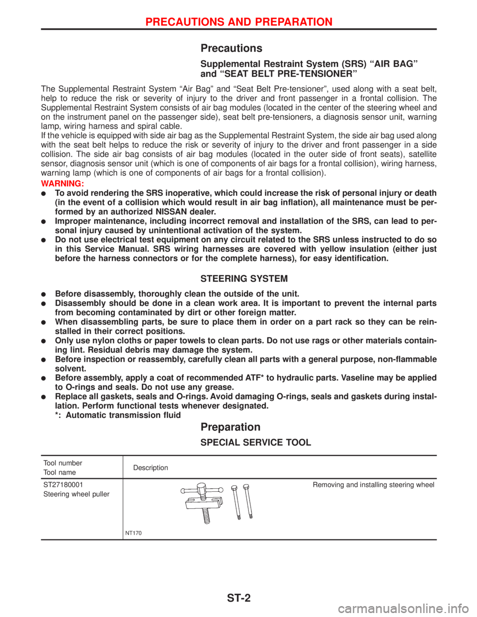
SPECIAL SERVICE TOOL
Tool number
Tool nameDescription
ST27180001
Steering wheel puller
NT170
Removing and installing steering wheel
PRECAUTIONS AND PREPARATION
ST-2