Page 1557 of 2267
ComponentsNCEM0008
RemovalNCEM00091. Remove engine RH side cover and under covers.
2. Drain engine oil.
3. Remove front exhaust tube.
Refer to FE section (ªEXHAUST SYSTEMº).
4. Set a suitable transmission jack under transaxle and lift engine
with engine slinger.
5. Remove center member.
6. Remove rear engine gussets.
SEM867F Oil pan sideGasket
Oil strainer
6.3 - 8.3
(0.64 - 0.85,
55.6 - 73.8)
Washer
Drain plug
29.4 - 39.2
(3.00 - 4.00, 21.69 - 28.91)
: N´m (kg-m, in-lb)
: N´m (kg-m, ft-lb)
: Use Genuine Liquid Gasket or equivalent
6.28 - 8.34 (0.641 - 0.851, 55.6 - 73.8)
6.28 - 8.34
(0.641 - 0.851, 55.6 - 73.8)
6.28 - 8.34
(0.641 - 0.851,
55.6 - 73.8) Oil pan
SEM067F Centre member
.SEM071FA Drain plug
Lower rear engine plate
Gusset
OIL PANQG
Components
EM-17
Page 1611 of 2267
b. Slide Tool by tapping on the side of the Tool with a hammer.
c. Remove steel oil pan.
d. Remove baffle plate.
5. Remove front exhaust tube.
6. Set a suitable transmission jack under transaxle and hoist
engine with engine slinger.
7. Remove center member.
8. Remove compressor gussets.
9. Remove rear cover plate.
SEM603E
NEM219
.Engine
front
.Baffle plate
SEM045D Center
member
Transmission jack
.SEM048D Front compressor
gusset
Compressor bracket
Rear compressor
gusset
SEM043D Rear cover plate
OIL PANSR20DE
Removal (Cont'd)
EM-71
Page 1618 of 2267
18. Set a suitable transmission jack under main bearing beam.
19. Remove RH engine mounting.
20. Remove RH engine mounting bracket.
21. Remove oil pump drive spacer.
CAUTION:
Be careful not to damage oil pump drive spacer and front oil
seal.
22. Remove front cover.
CAUTION:
IBe careful not to tear or damage the cylinder gasket.
IInspect for oil leakage at front oil seal. Replace seal if oil
leak is present.
23. Remove chain tensioner.
SEM039G Engine
front
Transmission
jack
SEM040G RH engine mounting
SEM041G RH engine mounting bracket
Water pump
SEM721E
.SEM032G Chain
tensioner
TIMING CHAINSR20DE
Removal (Cont'd)
EM-78
Page 1647 of 2267

WARNING:
IPosition vehicle on a flat and solid surface.
IPlace chocks at front and back of rear wheels.
IDo not remove engine until exhaust system has com-
pletely cooled;
Otherwise, you may burn yourself and/or fire may break
out in fuel line.
IBefore disconnecting fuel hose, release fuel pressure
from fuel line.
Refer to ªReleasing Fuel Pressureº in EC section.
IBe sure to hoist engine and transaxle in a safe manner.
IFor engines not equipped with engine slingers, attach
slingers and bolts described in PARTS CATALOG.
CAUTION:
IWhen lifting engine, be sure to clear surrounding parts.
Use special care for accelerator cable, brake lines and
brake master cylinder.
IIn hoisting the engine, always use engine slingers in a
safe manner.
IWhen removing drive shaft, be careful not to damage
grease seal of transaxle.
Removal
1. Remove engine under cover and hood.
2. Drain coolant from both cylinder block, and radiator.
3. Drain engine oil.
4. Remove vacuum hoses, fuel hoses, wires, harness and con-
nectors.
5. Remove exhaust tubes, ball joints and drive shafts.
6. Remove radiator and fans.
7. Remove drive belts.
8. Remove alternator, compressor and power steering oil pump
from engine.
9. Set a suitable transmission jack under transaxle. Hoist engine
with engine slinger.
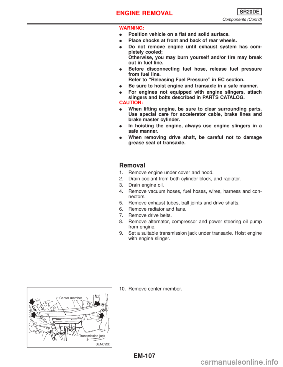
10. Remove center member.
SEM092D Center member
Transmission jack
ENGINE REMOVALSR20DE
Components (Cont'd)
EM-107
Page 1648 of 2267
11. Remove engine mounting bolts from both sides and then
slowly lower transmission jack.
12. Remove engine with transaxle as shown.
Installation
1. Install engine mounting bracket and fixing bolts.
Be sure that insulators are correctly positioned on the brack-
ets.
2. Carefully lower the engine onto engine mounting insulators.
SEM597D Front engine
mounting
NEM224
.Rear engine mounting
SEM195F
SEM312D Insulator Rubber seat
ENGINE REMOVALSR20DE
Removal (Cont'd)
EM-108
Page 1794 of 2267
Terminal Arrangement
YEL233C
TCM (Transmission control module)
ABS CONTROL UNIT
ECM (SR engine and QG engine)
ECM (CD engine)TCM (Transmission control module)
ELECTRICAL UNITS
Page 1799 of 2267

Regarding the procedures of NATS initialisation and NATS igni-
tion key ID registration, refer to CONSULT-II operation manual
for NATS.
Therefore, CONSULT-II NATS software (program card and
operation manual) must be kept strictly confidential to main-
tain the integrity of the anti-theft function.
lWhen servicing NATS (trouble diagnoses, system initialisa-
tion and additional registration of other NATS ignition key
IDs), it may be necessary to re-register original key identifi-
cation. Therefore, be sure to obtain all keys from vehicle
owner.
A maximum of four key IDs can be registered into NATS.
Precautions for Super Lock System
Locking the driver's door or front passenger's door with the key
or remote control will lock all doors and activate the Super Lock
System.
The Super Lock System is designed to prevent theft as it can
only be released when a front door is unlocked using a key or
remote control.
This means, none of the door locks can be operated from the
inside using the door lock knob when the Super Lock System is
activated.
General Precautions
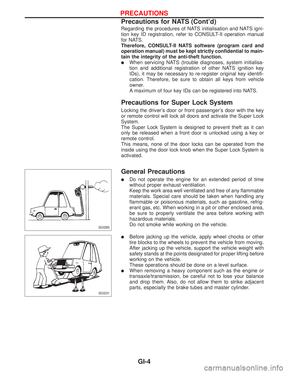
lDo not operate the engine for an extended period of time
without proper exhaust ventilation.
Keep the work area well ventilated and free of any flammable
materials. Special care should be taken when handling any
flammable or poisonous materials, such as gasoline, refrig-
erant gas, etc. When working in a pit or other enclosed area,
be sure to properly ventilate the area before working with
hazardous materials.
Do not smoke while working on the vehicle.
lBefore jacking up the vehicle, apply wheel chocks or other
tire blocks to the wheels to prevent the vehicle from moving.
After jacking up the vehicle, support the vehicle weight with
safety stands at the points designated for proper lifting before
working on the vehicle.
These operations should be done on a level surface.
lWhen removing a heavy component such as the engine or
transaxle/transmission, be careful not to lose your balance
and drop them. Also, do not allow them to strike adjacent
parts, especially the brake tubes and master cylinder.
SGI285
SGI231
PRECAUTIONS
Precautions for NATS (Cont'd)
GI-4
Page 1804 of 2267

lALPHABETICAL INDEXis provided at the end of this manual so that you can rapidly find the item and
page you are searching for.
lA QUICK REFERENCE INDEX,a black tab (e.g.) is provided on the first page. You can quickly
find the first page of each section by mating it to the section's black tab.
lTHE CONTENTSare listed on the first page of each section.
lTHE TITLEis indicated on the upper portion of each page and shows the part or system.
lTHE PAGE NUMBERof each section consists of two letters which designate the particular section and
a number (e.g. ªBR-5º).
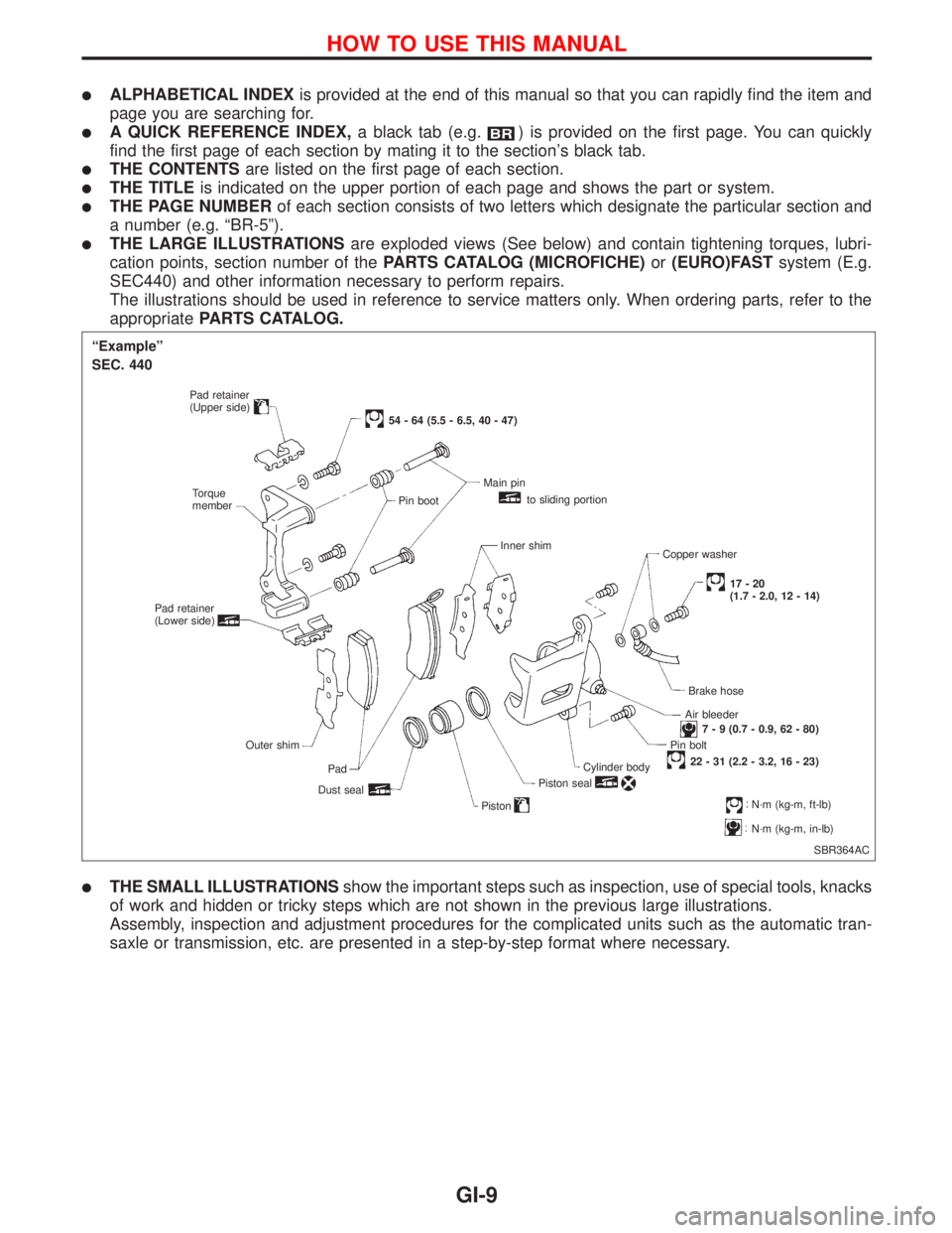
lTHE LARGE ILLUSTRATIONSare exploded views (See below) and contain tightening torques, lubri-
cation points, section number of thePARTS CATALOG (MICROFICHE)or(EURO)FASTsystem (E.g.
SEC440) and other information necessary to perform repairs.
The illustrations should be used in reference to service matters only. When ordering parts, refer to the
appropriatePARTS CATALOG.
lTHE SMALL ILLUSTRATIONSshow the important steps such as inspection, use of special tools, knacks
of work and hidden or tricky steps which are not shown in the previous large illustrations.
Assembly, inspection and adjustment procedures for the complicated units such as the automatic tran-
saxle or transmission, etc. are presented in a step-by-step format where necessary.
SBR364AC
ªExampleº
SEC. 440
Pad retainer
(Upper side)
Torque
member
Pad retainer
(Lower side)
Outer shim
Pad
Dust seal
54 - 64 (5.5 - 6.5, 40 - 47)
Pin bootMain pin
to sliding portion
Inner shim
Copper washer
17-20
(1.7 - 2.0, 12 - 14)
Brake hose
Air bleeder
7 - 9 (0.7 - 0.9, 62 - 80)
Pin bolt
22 - 31 (2.2 - 3.2, 16 - 23)
Cylinder body
Piston seal
PistonN´m (kg-m, ft-lb)
N´m (kg-m, in-lb)
HOW TO USE THIS MANUAL
GI-9