Page 936 of 2267
Component InspectionNCEC0078ENGINE COOLANT TEMPERATURE SENSORNCEC0078S01Check resistance as shown in the figure.
Temperature ÉC (ÉF) Resistance kW
20 (68)2.1 - 2.9
50 (122)0.68 - 1.00
90 (194)0.236 - 0.260
If NG, replace engine coolant temperature sensor.
4 DETECT MALFUNCTIONING PART
Check the following.
IHarness for open or short between ECM and engine coolant temperature sensor
IHarness for open or short between engine coolant temperature sensor and TCM (Transmission control module)
©Repair open circuit or short to ground or short to power in harness or connectors.
5 CHECK ENGINE COOLANT TEMPERATURE SENSOR
Refer to ªComponent Inspectionº, EC-SR-136.
OK or NG
OK©GO TO 6.
NG©Replace engine coolant temperature sensor.
6 CHECK INTERMITTENT INCIDENT
Perform ªTROUBLE DIAGNOSIS FOR INTERMITTENT INCIDENTº, EC-SR-114.
©INSPECTION END
SEF152P
SEF012P
DTC P0115 ENGINE COOLANT TEMPERATURE SENSOR
(ECTS) (CIRCUIT)SR20DE
Component Inspection
EC-136
Page 942 of 2267

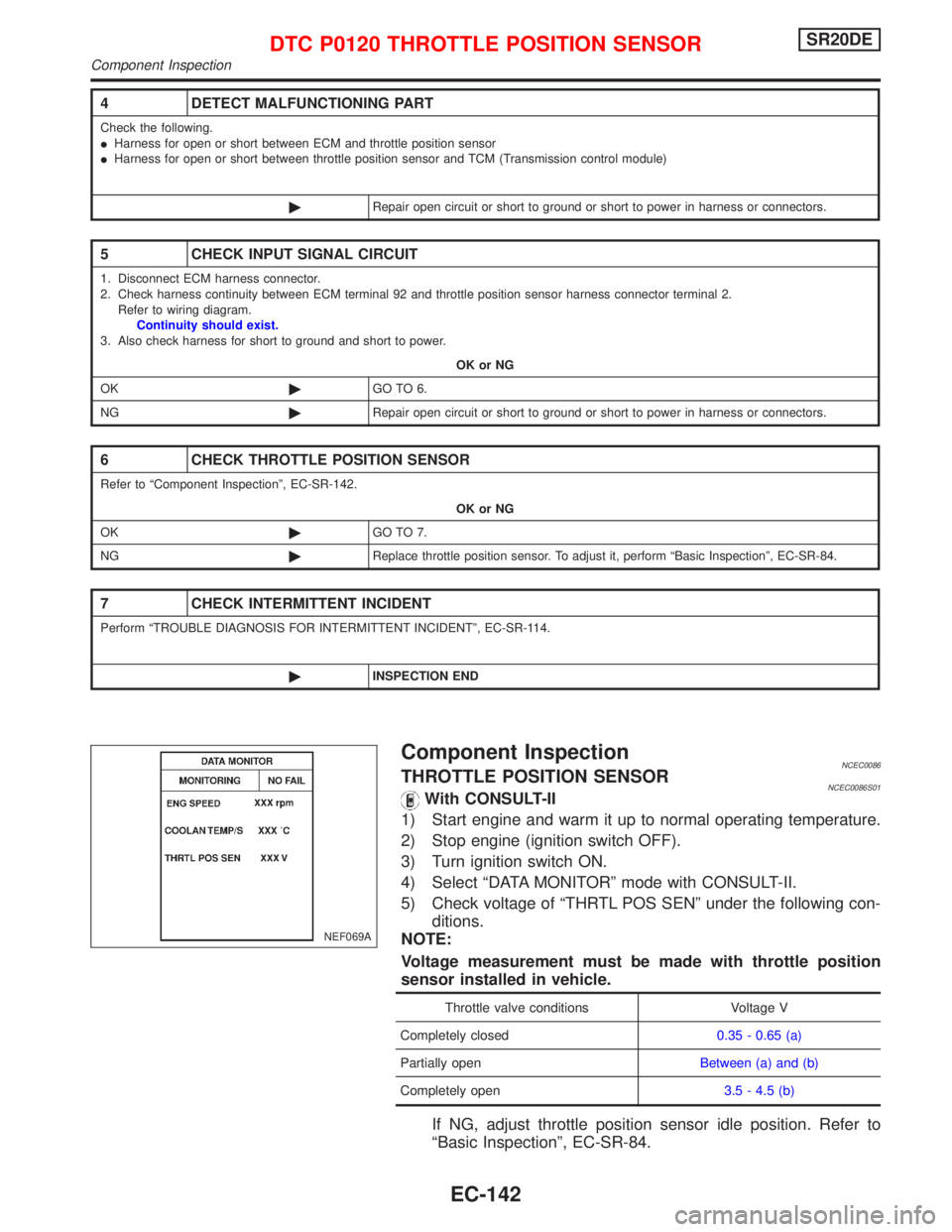
Component InspectionNCEC0086THROTTLE POSITION SENSORNCEC0086S01With CONSULT-II
1) Start engine and warm it up to normal operating temperature.
2) Stop engine (ignition switch OFF).
3) Turn ignition switch ON.
4) Select ªDATA MONITORº mode with CONSULT-II.
5) Check voltage of ªTHRTL POS SENº under the following con-
ditions.
NOTE:
Voltage measurement must be made with throttle position
sensor installed in vehicle.
Throttle valve conditions Voltage V
Completely closed0.35 - 0.65 (a)
Partially openBetween (a) and (b)
Completely open3.5 - 4.5 (b)
If NG, adjust throttle position sensor idle position. Refer to
ªBasic Inspectionº, EC-SR-84.
4 DETECT MALFUNCTIONING PART
Check the following.
IHarness for open or short between ECM and throttle position sensor
IHarness for open or short between throttle position sensor and TCM (Transmission control module)
©Repair open circuit or short to ground or short to power in harness or connectors.
5 CHECK INPUT SIGNAL CIRCUIT
1. Disconnect ECM harness connector.
2. Check harness continuity between ECM terminal 92 and throttle position sensor harness connector terminal 2.
Refer to wiring diagram.
Continuity should exist.
3. Also check harness for short to ground and short to power.
OK or NG
OK©GO TO 6.
NG©Repair open circuit or short to ground or short to power in harness or connectors.
6 CHECK THROTTLE POSITION SENSOR
Refer to ªComponent Inspectionº, EC-SR-142.
OK or NG
OK©GO TO 7.
NG©Replace throttle position sensor. To adjust it, perform ªBasic Inspectionº, EC-SR-84.
7 CHECK INTERMITTENT INCIDENT
Perform ªTROUBLE DIAGNOSIS FOR INTERMITTENT INCIDENTº, EC-SR-114.
©INSPECTION END
NEF069A
DTC P0120 THROTTLE POSITION SENSORSR20DE
Component Inspection
EC-142
Page 1036 of 2267
Wiring DiagramNCEC0581
YEC839
: Detectable line for DTC
: Non-detectable line for DTC
: Hyper CVT models
ECMTCM
(TRANSMISSION
CONTROL
MODULE) CRANKSHAFT
POSITION
SENSOR (OBD)
DTC P0335 CRANKSHAFT POSITION SENSOR (CKPS) (OBD)SR20DE
Wiring Diagram
EC-236
Page 1037 of 2267

Diagnostic ProcedureNCEC0582
1 RETIGHTEN GROUND SCREWS
1. Turn ignition switch ªOFFº.
2. Loosen and retighten engine ground screws.
©GO TO 2.
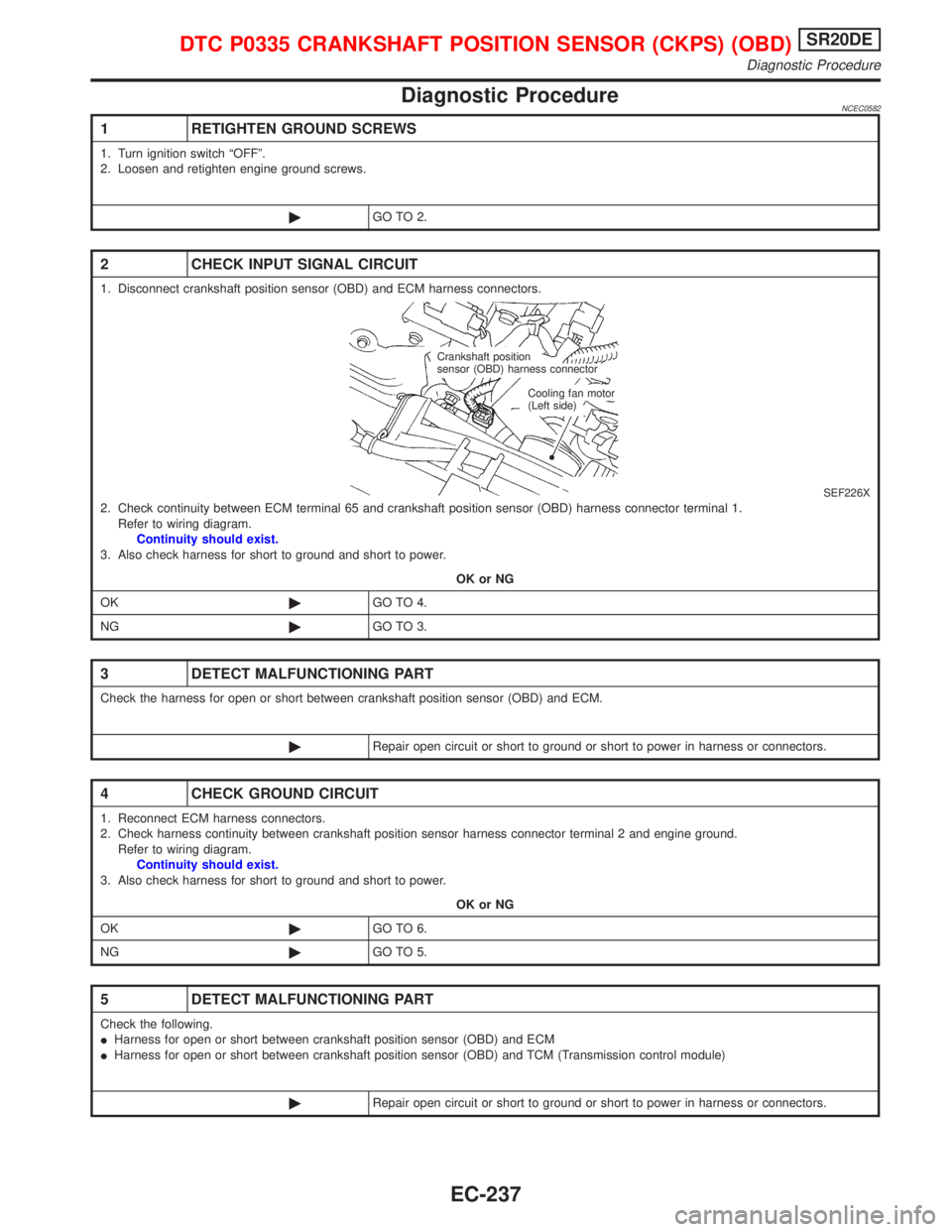
2 CHECK INPUT SIGNAL CIRCUIT
1. Disconnect crankshaft position sensor (OBD) and ECM harness connectors.
SEF226X2. Check continuity between ECM terminal 65 and crankshaft position sensor (OBD) harness connector terminal 1.
Refer to wiring diagram.
Continuity should exist.
3. Also check harness for short to ground and short to power.
OK or NG
OK©GO TO 4.
NG©GO TO 3.
3 DETECT MALFUNCTIONING PART
Check the harness for open or short between crankshaft position sensor (OBD) and ECM.
©Repair open circuit or short to ground or short to power in harness or connectors.
4 CHECK GROUND CIRCUIT
1. Reconnect ECM harness connectors.
2. Check harness continuity between crankshaft position sensor harness connector terminal 2 and engine ground.
Refer to wiring diagram.
Continuity should exist.
3. Also check harness for short to ground and short to power.
OK or NG
OK©GO TO 6.
NG©GO TO 5.
5 DETECT MALFUNCTIONING PART
Check the following.
IHarness for open or short between crankshaft position sensor (OBD) and ECM
IHarness for open or short between crankshaft position sensor (OBD) and TCM (Transmission control module)
©Repair open circuit or short to ground or short to power in harness or connectors.
Crankshaft position
sensor (OBD) harness connector
Cooling fan motor
(Left side)
DTC P0335 CRANKSHAFT POSITION SENSOR (CKPS) (OBD)SR20DE
Diagnostic Procedure
EC-237
Page 1069 of 2267

8 CHECK IACV-AAC VALVE
Refer to ªComponent Inspectionº, EC-SR-270.
OK or NG
OK©GO TO 9.
NG©Replace IACV-AAC valve.
9 REPLACE IACV-AAC VALVE
1. Replace IACV-AAC valve assembly.
2. Perform ªIdle Air Volume Learningº, EC-46.
Is the result CMPLT or INCMP?
CMPLT or INCMP
CMPLT©INSPECTION END
INCMP©Follow the construction of ªIdle Air Volume Learningº.
10 CHECK TARGET IDLE SPEED
1. Turn ignition switch ªOFFº.
2. Reconnect all harness connectors and vacuum hoses.
3. Start engine and warm it up to normal operating temperature.
4. Also warm up transmission to normal operating temperature
IFor CVT models with CONSULT-II, drive vehicle until ªFLUID TEMP SEº in ªDATA MONITORº mode of ªCVTº system
indicates less than 0.9V.
IFor CVT models without CONSULT-II and M/T models, drive vehicle for 10 minutes.
5. Stop vehicle with engine running.
6. Check target idle speed.
M/T: 750 50 rpm
A/T: 750 50 rpm (in ªPº or ªNº position)
OK or NG
OK©GO TO 11.
NG©Perform ªIdle Air Volume Learningº, EC-45.
11 CHECK INTERMITTENT INCIDENT
Perform ªTROUBLE DIAGNOSIS FOR INTERMITTENT INCIDENTº, EC-SR-114.
©INSPECTION END
DTC P0505 IDLE AIR CONTROL VALVE (IACV) Ð
AUXILIARY AIR CONTROL (AAC) VALVESR20DE
Diagnostic Procedure (Cont'd)
EC-269
Page 1075 of 2267
4 DETECT MALFUNCTIONING PART
Check the following.
IHarness for open or short between throttle position switch and ECM
IHarness for open or short between throttle position switch and TCM (Transmission control module)
©Repair open circuit or short to ground or short to power in harness or connectors.
5 ADJUST THROTTLE POSITION SWITCH IDLE POSITION
Perform Basic Inspection, EC-SR-84.
©GO TO 6.
6 CHECK CLOSED THROTTLE POSITION SWITCH
Refer to ªComponent Inspectionº, EC-SR-276.
OK or NG
OK©GO TO 7.
NG©Replace throttle position switch.
7 CHECK THROTTLE POSITION SENSOR
Refer to ªComponent Inspectionº, EC-SR-142.
OK or NG
OK©GO TO 8.
NG©Replace throttle position sensor.
8 CHECK INTERMITTENT INCIDENT
Perform ªTROUBLE DIAGNOSIS FOR INTERMITTENT INCIDENTº, EC-SR-114.
©INSPECTION END
DTC P0510 CLOSED THROTTLE POSITION SWITCH
(IF SO EQUIPPED)SR20DE
Diagnostic Procedure (Cont'd)
EC-275
Page 1083 of 2267
YEC848
: Detectable line for DTC
: Non-detectable line for DTC
: Hyper CVT models REFRIGERANT
SENSOR
TCM
(TRANSMISSION
CONTROL
MODULE) ECM
DTC P1217 OVERHEAT (COOLING SYSTEM)SR20DE
Wiring Diagram (Cont'd)
EC-283
Page 1092 of 2267
Wiring DiagramNCEC0331
YEC839
: Detectable line for DTC
: Non-detectable line for DTC
: Hyper CVT models
ECMTCM
(TRANSMISSION
CONTROL
MODULE) CRANKSHAFT
POSITION
SENSOR (OBD)
DTC P1336 CRANKSHAFT POSITION SENSOR
(CKPS) (OBD) (COG)SR20DE
Wiring Diagram
EC-292