1999 NISSAN PRIMERA transmission
[x] Cancel search: transmissionPage 1805 of 2267
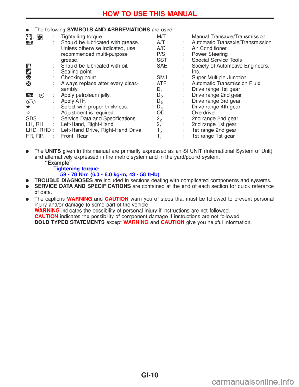
lThe followingSYMBOLS AND ABBREVIATIONSare used:
,: Tightening torque
: Should be lubricated with grease.
Unless otherwise indicated, use
recommended multi-purpose
grease.
: Should be lubricated with oil.
: Sealing point
: Checking point
: Always replace after every disas-
sembly.
pP: Apply petroleum jelly.
: Apply ATF.
H: Select with proper thickness.
I: Adjustment is required.
SDS : Service Data and Specifications
LH, RH : Left-Hand, Right-Hand
LHD, RHD : Left-Hand Drive, Right-Hand Drive
FR, RR : Front, RearM/T : Manual Transaxle/Transmission
A/T : Automatic Transaxle/Transmission
A/C : Air Conditioner
P/S : Power Steering
SST : Special Service Tools
SAE : Society of Automotive Engineers,
Inc.
SMJ : Super Multiple Junction
ATF : Automatic Transmission Fluid
D
1: Drive range 1st gear
D
2: Drive range 2nd gear
D
3: Drive range 3rd gear
D
4: Drive range 4th gear
OD : Overdrive
2
2: 2nd range 2nd gear
2
1: 2nd range 1st gear
1
2: 1st range 2nd gear
1
1: 1st range 1st gear
lTheUNITSgiven in this manual are primarily expressed as an SI UNIT (International System of Unit),
and alternatively expressed in the metric system and in the yard/pound system.
ªExampleº
Tightening torque:
59 - 78 N´m (6.0 - 8.0 kg-m, 43 - 58 ft-lb)
lTROUBLE DIAGNOSESare included in sections dealing with complicated components and systems.
lSERVICE DATA AND SPECIFICATIONSare contained at the end of each section for quick reference
of data.
lThe captionsWARNINGandCAUTIONwarn you of steps that must be followed to prevent personal
injury and/or damage to some part of the vehicle.
WARNINGindicates the possibility of personal injury if instructions are not followed.
CAUTIONindicates the possibility of component damage if instructions are not followed.
BOLD TYPED STATEMENTSexceptWARNINGandCAUTIONgive you helpful information.
HOW TO USE THIS MANUAL
GI-10
Page 1815 of 2267
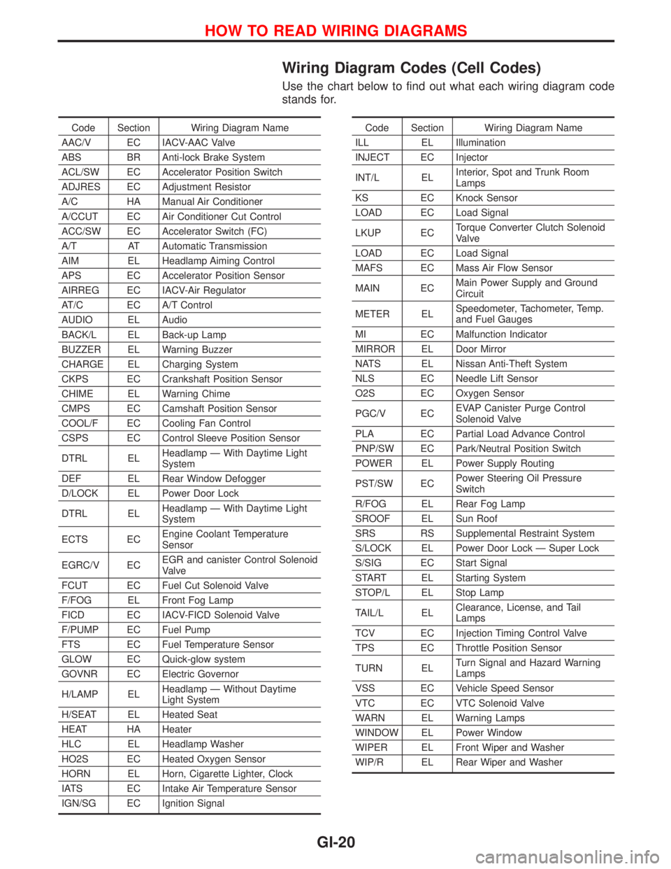
Wiring Diagram Codes (Cell Codes)
Use the chart below to find out what each wiring diagram code
stands for.
Code Section Wiring Diagram Name
AAC/V EC IACV-AAC Valve
ABS BR Anti-lock Brake System
ACL/SW EC Accelerator Position Switch
ADJRES EC Adjustment Resistor
A/C HA Manual Air Conditioner
A/CCUT EC Air Conditioner Cut Control
ACC/SW EC Accelerator Switch (FC)
A/T AT Automatic Transmission
AIM EL Headlamp Aiming Control
APS EC Accelerator Position Sensor
AIRREG EC IACV-Air Regulator
AT/C EC A/T Control
AUDIO EL Audio
BACK/L EL Back-up Lamp
BUZZER EL Warning Buzzer
CHARGE EL Charging System
CKPS EC Crankshaft Position Sensor
CHIME EL Warning Chime
CMPS EC Camshaft Position Sensor
COOL/F EC Cooling Fan Control
CSPS EC Control Sleeve Position Sensor
DTRL ELHeadlamp Ð With Daytime Light
System
DEF EL Rear Window Defogger
D/LOCK EL Power Door Lock
DTRL ELHeadlamp Ð With Daytime Light
System
ECTS ECEngine Coolant Temperature
Sensor
EGRC/V ECEGR and canister Control Solenoid
Valve
FCUT EC Fuel Cut Solenoid Valve
F/FOG EL Front Fog Lamp
FICD EC IACV-FICD Solenoid Valve
F/PUMP EC Fuel Pump
FTS EC Fuel Temperature Sensor
GLOW EC Quick-glow system
GOVNR EC Electric Governor
H/LAMP ELHeadlamp Ð Without Daytime
Light System
H/SEAT EL Heated Seat
HEAT HA Heater
HLC EL Headlamp Washer
HO2S EC Heated Oxygen Sensor
HORN EL Horn, Cigarette Lighter, Clock
IATS EC Intake Air Temperature Sensor
IGN/SG EC Ignition SignalCode Section Wiring Diagram Name
ILL EL Illumination
INJECT EC Injector
INT/L ELInterior, Spot and Trunk Room
Lamps
KS EC Knock Sensor
LOAD EC Load Signal
LKUP ECTorque Converter Clutch Solenoid
Valve
LOAD EC Load Signal
MAFS EC Mass Air Flow Sensor
MAIN ECMain Power Supply and Ground
Circuit
METER ELSpeedometer, Tachometer, Temp.
and Fuel Gauges
MI EC Malfunction Indicator
MIRROR EL Door Mirror
NATS EL Nissan Anti-Theft System
NLS EC Needle Lift Sensor
O2S EC Oxygen Sensor
PGC/V ECEVAP Canister Purge Control
Solenoid Valve
PLA EC Partial Load Advance Control
PNP/SW EC Park/Neutral Position Switch
POWER EL Power Supply Routing
PST/SW ECPower Steering Oil Pressure
Switch
R/FOG EL Rear Fog Lamp
SROOF EL Sun Roof
SRS RS Supplemental Restraint System
S/LOCK EL Power Door Lock Ð Super Lock
S/SIG EC Start Signal
START EL Starting System
STOP/L EL Stop Lamp
TAIL/L ELClearance, License, and Tail
Lamps
TCV EC Injection Timing Control Valve
TPS EC Throttle Position Sensor
TURN ELTurn Signal and Hazard Warning
Lamps
VSS EC Vehicle Speed Sensor
VTC EC VTC Solenoid Valve
WARN EL Warning Lamps
WINDOW EL Power Window
WIPER EL Front Wiper and Washer
WIP/R EL Rear Wiper and Washer
HOW TO READ WIRING DIAGRAMS
GI-20
Page 1819 of 2267
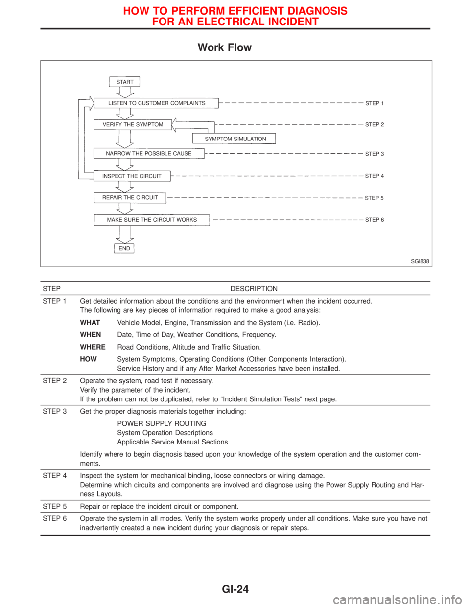
Work Flow
STEP DESCRIPTION
STEP 1 Get detailed information about the conditions and the environment when the incident occurred.
The following are key pieces of information required to make a good analysis:
WHATVehicle Model, Engine, Transmission and the System (i.e. Radio).
WHENDate, Time of Day, Weather Conditions, Frequency.
WHERERoad Conditions, Altitude and Traffic Situation.
HOWSystem Symptoms, Operating Conditions (Other Components Interaction).
Service History and if any After Market Accessories have been installed.
STEP 2 Operate the system, road test if necessary.
Verify the parameter of the incident.
If the problem can not be duplicated, refer to ªIncident Simulation Testsº next page.
STEP 3 Get the proper diagnosis materials together including:
POWER SUPPLY ROUTING
System Operation Descriptions
Applicable Service Manual Sections
Identify where to begin diagnosis based upon your knowledge of the system operation and the customer com-
ments.
STEP 4 Inspect the system for mechanical binding, loose connectors or wiring damage.
Determine which circuits and components are involved and diagnose using the Power Supply Routing and Har-
ness Layouts.
STEP 5 Repair or replace the incident circuit or component.
STEP 6 Operate the system in all modes. Verify the system works properly under all conditions. Make sure you have not
inadvertently created a new incident during your diagnosis or repair steps.
SGI838 START
LISTEN TO CUSTOMER COMPLAINTS
VERIFY THE SYMPTOM
SYMPTOM SIMULATION
NARROW THE POSSIBLE CAUSE
INSPECT THE CIRCUIT
REPAIR THE CIRCUIT
MAKE SURE THE CIRCUIT WORKS
ENDSTEP 1
STEP 2
STEP 3
STEP 4
STEP 5
STEP 6
HOW TO PERFORM EFFICIENT DIAGNOSIS
FOR AN ELECTRICAL INCIDENT
GI-24
Page 1969 of 2267
A
AAC/V - Wiring diagram....EC-QG-276, EC-SR-265
ABS (anti-lock brake system).........................BR-50
A/C control linkage adjustment (manual
A/C) .............................................................HA-82
A/C control operation (auto A/C) ....................HA-19
A/C diagnostic work flow (auto A/C) ..............HA-26
A/C performance chart ...................................HA-35
A/C performance test diagnoses....................HA-33
A/C relay.........................................................HA-78
A/C service data specification ......................HA-118
A/C switch ......................................................HA-78
A/C symptom chart (auto A/C) .......................HA-28
A/C trouble diagnoses (auto A/C) ..................HA-26
Accelerator control system ...............................FE-3
Accelerator position sensor ...................EC-CD-108
Accelerator position switch ....................EC-CD-108
Accelerator wire adjustment .............................FE-4
A/CCUT - Wiring diagram ......................EC-CD-127
Air bag disposal..............................................RS-27
Air bag precautions ...........................................GI-3
Air bleeding for brake system ..........................BR-8
Air cleaner filter replacement ............MA-23, 34, 44
Air conditioner cut
control .....EC-QG-24, EC-SR-26, EC-CD-20, 126
Air flow meter - See Mass air flow
sensor ............................EC-QG-110, EC-SR-120
Air mix. door motor.........................................HA-92
Alternator ..................................................EL-53, 56
Ambient sensor ..............................................HA-86
Antenna .........................................................EL-229
Anti-lock brake system - See ABS .................BR-50
APS - Wiring diagram ............................EC-CD-109
A/T - Wiring diagram - AT - FTS .....................AT-56
A/T - Wiring diagram - AT - MAIN ...................AT-45
A/T - Wiring diagram - AT - PNP/SW..............AT-50
A/T - Wiring diagram - AT - VSS A/T ..............AT-64
A/T diagnosis communication line .........EC-SR-295
A/T fluid temperature sensor...........................AT-54
A/T trouble diagnoses ...............................AT-29, 30
A/T Wiring diagram - AT - ENG SS ................AT-67
A/T Wiring diagram AT - LPSV .......................AT-76
A/T Wiring diagram AT - TCV .........................AT-71
A/T Wiring diagram AT - TPS..........................AT-81
ATDIAG - Wiring diagram ......................EC-SR-296
Audio .............................................................EL-216
AUDIO - Wiring diagram ...............................EL-219
Audio and A/C control removal and
installation - See Instrument panel .............BT-15
Auto air conditioner - Wiring diagram ............HA-42
Automatic amplifier .........................................HA-87
Automatic transaxle number............................GI-44
Automatic transmission fluid
replacement..........................................MA-49, 50
Auxiliary air control (AAC)
valve ..............................EC-QG-274, EC-SR-263BBack door opener - See Back door ............BT-9, 11
Back door trim.................................................BT-30
Back door window ....................................BT-35, 56
Back-up lamp ................................................EL-107
BACK/L - Wiring diagram..............................EL-107
Ball joint front axle ....................................FA-32, 33
Base idle air volume
initialiging ...........................EC-QG-33, EC-SR-46
Basic inspection ....................EC-QG-72, EC-SR-84
Battery .............................................................EL-29
Body alignment ...............................................BT-60
Brake booster .................................................BR-18
Brake control valve (Proportioning
valve)...........................................................BR-11
Brake fluid change ...........................................BR-7
Brake fluid level .............................................MA-51
Brake fluid level and line check .......................BR-7
Brake hydraulic line ..........................................BR-9
Brake inspection ............................................MA-51
Brake lining wear temporary checking ..........MA-51
Brake pedal ....................................................BR-13
Bulb specifications ........................................EL-137
Bumper, front ....................................................BT-5
Bumper, rear .......................................BT-5, 7, 9, 11
BUZZER - Wiring diagram ............................EL-181
C
Camshaft inspection ...............EM-35, 91, 138, 147,
183, 192, 196
Camshaft position sensor
(CMPS) ..........................EC-QG-238, EC-SR-239
Camshaft position sensor (PHASE) ......EC-QG-238
Canister-See EVAP
canister ..............................EC-QG-25, EC-SR-27
CHARGE - Wiring diagram .............................EL-53
Charging system .............................................EL-53
Chassis and body maintenance ....................MA-48
CHIME - Wiring diagram ...............................EL-181
Cigarette lighter.............................................EL-203
Circuit breaker.................................................EL-22
CKPS - Wiring diagram....EC-QG-234, EC-SR-236,
292, EC-CD-115
Clock .............................................................EL-203
Closed throttle position switch ...............EC-SR-271
Clutch cover ....................................................CL-13
Clutch damper ................................................CL-10
Clutch disc ......................................................CL-13
Clutch fluid level.............................................MA-48
Clutch master cylinder ......................................CL-8
Clutch operating cylinder ..................................CL-9
Clutch release mechanism..............................CL-11
CMPS - Wiring diagram ....EC-QG-240, EC-SR-242
Coil spring (rear) .............................................RA-11
Collision diagnosis..........................................RS-57
Combination meter........................................EL-138
ALPHABETICAL INDEX
IDX-2
Page 1972 of 2267
How to erase DTC for OBD
system ...............................EC-QG-44, EC-SR-56
HSEAT - Wiring diagram...............................EL-234
Hydraulic lash adjuster inspection .........EM-96, 189
I
IACV-AAC valve ................EC-QG-274, EC-SR-263
IATS - Wiring diagram .......EC-QG-117, EC-SR-128
Identification plate............................................GI-44
Idle air control (IAC)
system ...........................EC-QG-274, EC-SR-263
Idle air control valve
(IACV) ............................EC-QG-274, EC-SR-263
Idle mixture ratio ...................EC-QG-32, EC-SR-34
Idle speed .............................EC-QG-32, EC-SR-34
IGN/SG - Wiring diagram .......................EC-SR-308
Ignition coil .............................................EC-SR-310
Ignition control system ......EC-QG-323, EC-SR-306
Ignition timing ........................EC-QG-32, EC-SR-34
Ignition wire inspection ..............MA-36, EC-SR-229
ILL - Wiring diagram .....................................EL-125
Illumination ....................................................EL-124
INJECT - Wiring diagram ..EC-QG-319, EC-SR-303
Injection nozzle inspection .............................MA-46
Injection timing control valve ...................EC-CD-82
Injector ...................................................EC-QG-318
Injector removal and
installation..........................EC-QG-30, EC-SR-32
Input shaft (FF M/T) .................................MT-21, 58
Instrument panel .............................................BT-15
INT/L - Wiring diagram..................................EL-132
Intake air temparature
sensor ............................EC-QG-116, EC-SR-127
Intake door control linkage adjustment ..........HA-83
Intake door motor .....................................HA-81, 83
Intake valve timing control solenoid
valve ...................................................EC-QG-284
Interior .............................................................BT-18
Interior lamp ..........................................EL-124, 130
K
Knock sensor (KS) .......................EC-QG-228, 229,
EC-SR-230, 231
KS - Wiring diagram ..............................EC-QG-229
L
License lamp .................................................EL-100
Lifting points ....................................................GI-46
Line pressure solenoid valve ..........................AT-74
Line pressure test (A/T) ..................................AT-35
Liquid gasket application .................................EM-5
LOAD - Wiring diagram .........................EC-QG-352
Location of electrical units ............................EL-365
Lubricants.......................................................MA-16Lubrication circuit (engine) ...................LC-4, 15, 26
Lubrication-locks, hinges and hood
latches ........................................................MA-54
Luggage compartment trim .............................BT-29
Luggage room lamp ......................................EL-131
M
MAFS - Wiring
diagram .......EC-QG-112, EC-SR-122, EC-CD-63
MAIN - Wiring
diagram .......EC-QG-103, EC-SR-115, EC-CD-59
Mainshaft (M/T) ........................................MT-24, 63
Malfunction indicator lamp
(MIL) ..................................EC-QG-45, EC-SR-58
Manual transmission number ..........................GI-44
Manual transmission oil replacement ......MA-48, 49
Mass air flow sensor
(MAFS)........EC-QG-110, EC-SR-120, EC-CD-62
METER - Wiring diagram .....................EL-141, 146
MIL & Data link connectors
circuit .............................EC-QG-354, EC-SR-329
MIL/DL - Wiring
diagram .....EC-QG-354, EC-SR-329, EC-CD-142
MIRROR - Wiring diagram ............................EL-231
Mirror defogger .............................................EL-207
Mirror, door......................................................BT-58
Mirror, out side ................................................BT-58
Misfire ................................EC-QG-222, EC-SR-224
Mode door control linkage adjustment ...........HA-82
Model variation ................................................GI-41
Molding - See Exterior ....................................BT-31
M/T major overhaul ..................................MT-14, 47
M/T removal and installation ..........................MT-10
Mud guard - See Exterior ...............................BT-37
MULTI - Wiring diagram ................................EL-298
Multi-remote control system..........................EL-296
Multiport fuel injection (MFI)
system ...............................EC-QG-21, EC-SR-23
Multiport fuel injection precautions ....................GI-6
N
NATS (Nissan anti-theft system)...................EL-342
NATS (Nissan anti-theft system)
precautions ..............................................GI-3, 25
NATS - Wiring diagram .................................EL-343
Needle lift sensor .....................................EC-CD-97
Neutral position switch ......EC-QG-313, EC-SR-298
NLS - Wiring diagram ..............................EC-CD-98
NVH troubleshooting (BR)................................BR-6
NVH troubleshooting (CL) ................................CL-3
NVH troubleshooting (EM) ...............EM-11, 64, 121
NVH troubleshooting (M/T) ..............................MT-7
NVH troubleshooting (RA)................................RA-3
ALPHABETICAL INDEX
IDX-5
Page 1974 of 2267
S/SIG - Wiring diagram ....EC-QG-333, EC-SR-313,
EC-CD-145
Stabilizer bar (front) ........................................FA-32
Stall test (A/T) .................................................AT-34
Standardized relay ............................................EL-8
START - Wiring diagram .................................EL-37
Start signal .................EC-QG-38, 332, EC-SR-312,
EC-CD-145
Starter .......................................................EL-37, 43
Starting system ...............................................EL-37
Steering gear and linkage inspection ............MA-53
Steering knuckle........................................FA-11, 12
Stop lamp ......................................................EL-104
STOP/L - Wiring diagram..............................EL-104
Sun roof, electric ...........................................EL-230
Sunload sensor ..............................................HA-86
Sunroof .....................................................BT-31, 46
Super lock .............................................EL-245, 265
Supplemental Restraint System .......................RS-8
Supplemental restraint system - Wiring
diagram .......................................................RS-33
Symbols and abbreviations .............................GI-38
Symptom matrix chart ...........EC-QG-82, EC-SR-94
Synchronizer (M/T) ......................MT-22, 27, 59, 65
System readiness test (SRT) code ..........EC-SR-50
T
Tachometer ...........................................EL-141, 146
Tail lamp ........................................................EL-100
TCM circuit diagram ........................................AT-10
TCM inspection table ......................................AT-41
Temperature control cable and linkage
adjustment ..................................................HA-83
THEFT - Wiring diagram ...............................EL-316
Theft warning system ....................................EL-311
Thermal protector .........................................HA-113
Thermo control amp .......................................HA-80
Thermostat ..........................................LC-11, 23, 34
Third link (front susp.) .....................................FA-29
Three way catalyst ............EC-QG-258, EC-SR-246
Three way catalyst precautions.........................GI-6
Throttle position sensor
(TPS) .............................EC-QG-125, EC-SR-137
Throttle position sensor
adjustment .........................EC-QG-72, EC-SR-84
Throttle position switch ...............EC-SR-271, AT-85
Tightening torque of standard bolts.................GI-50
Time control system ......................................EL-306
Timing belt....................................................EM-131
Timing chain.............................................EM-19, 75
Tire rotation ....................................................MA-53
Tire size ...........................................................GI-45
Torque converter installation .........................AT-117
Torque convertor clutch solenoid valve...........AT-69
Tow truck towing ..............................................GI-46
Towing point.....................................................GI-49
TP/SW - Wiring diagram ........................EC-SR-273
TPS - Wiring diagram .......EC-QG-128, EC-SR-140
Transmission case (M/T) ................................MT-39Transverse link (front) .....................................FA-32
Trim .................................................................BT-18
Triple pressure switch ....................................HA-79
Trouble diagnoses ...........................................GI-35
Trunk lid ............................................................BT-7
Trunk lid opener - See Trunk lid .......................BT-7
Trunk room lamp...................................EL-130, 131
Trunk room trim...............................................BT-28
Turbocharger........................................EM-156, 201
Turbocharger precautions..................................GI-6
TURN - Wiring diagram.................................EL-118
Turn signal lamp............................................EL-117
Two trip detection logic .........EC-QG-36, EC-SR-48
U
Upper link (front susp.) ...................................FA-29
V
Vacuum hose (brake system).........................BR-20
Vacuum hose drawing (Engine
control) ............EC-QG-19, EC-SR-21, EC-CD-13
Valve clearance .............................EM-40, 179, 191
Valve guide..............EM-36, 93, 142, 180, 189, 197
Valve lifter ..............................EM-40, 145, 179, 198
Valve seat................EM-38, 95, 143, 182, 190, 198
Valve spring.............EM-39, 96, 145, 179, 189, 197
Vehicle identification number...........................GI-43
Vehicle speed sensor
(VSS) ..........EC-QG-267, EC-SR-255, EC-CD-70
Viscosity number (SAE) .................................MA-17
VSS - Wiring
diagram .......EC-QG-269, EC-SR-257, EC-CD-71
W
WARN - Wiring diagram ...............................EL-167
Warning buzzer .............................................EL-180
Warning chime ..............................................EL-180
Warning lamps ..............................................EL-165
Washer, front .................................................EL-186
Washer, rear..................................................EL-193
Water cock control rod adjustment ................HA-82
Water pump ........................................LC-10, 22, 33
Water temperature gauge .....................EL-141, 146
Weatherstrip - See Exterior ............................BT-31
Wheel alignment (front) ..................................FA-35
Wheel alignment (rear).....................................RA-6
Wheel balance ...............................................MA-53
Wheel bearing (front axle) ....................FA-6, 12, 35
Wheel bearing (rear) ........................................RA-5
Wheel hub (front) ............................................FA-12
Wheel hub (rear) ..............................................RA-7
Wheel sensors (ABS) .....................................BR-53
Wheel size .......................................................GI-45
Wheelbase (Dimensions) ................................GI-45
ALPHABETICAL INDEX
IDX-7
Page 2021 of 2267
Shown below are Pre-delivery Inspection Items required for the new vehicle. It is recommended that
necessary items other than those listed here be added, paying due regard to the conditions in each
country.
Perform applicable items on each model. Consult text of this section for specifications.
UNDER HOOD � engine off
Radiator coolant level and coolant hose con-
nections for leaks
Battery fluid level, specific gravity and condi-
tions of battery terminals
Drive belts tension
Fuel filter for water or dust, fuel lines and con-
nections for leaks
Engine oil level and oil leaks
Clutch and brake reservoir fluid level and fluid
lines for leaks
Windshield and rear window washer and head-
lamp cleaner reservoir fluid level
Power steering reservoir fluid level and hose
connections for leaks
ON INSIDE AND OUTSIDE
Remove front spring/strut spacer (If applicable)
Operation of all instruments, gauges, lights and
accessories
Operation of horn(s), wiper and washer
Steering lock for operation
Check air conditioner for gas leaks
Front and rear seats, and seat belts for opera-
tion
All moldings, trims and fittings for fit and align-
ment
All windows for operation and alignment
Hood, trunk lid, door panels for fit and align-
ment
Latches, keys and locks for operation
Weatherstrips for adhesion and fit
Headlamp aiming
Tighten wheel nuts (Inc. inner nuts if appli-
cable)
Tire pressure (Inc. spare tire)
Check front wheels for toe-in
Install clock/voltmeter/room lamp fuse (If appli-
cable)
Install deodorizing filter to air purifier (If appli-
cable)
Remove wiper blade protectors (If applicable)
UNDER BODY
Manual transmission/transaxle, transfer and
differential gear oil level
Brake and fuel lines and oil/fluid reservoirs for
leaks
Tighten bolts and nuts of steering linkage and
gear box, suspension, propeller shafts and
drive shafts
Tighten rear body bolts and nuts (Models with
wooden bed only)
ROAD TEST
Clutch operation
Parking brake operation
Service brake operation
Automatic transmission/transaxle shift timing
and kickdown
Steering control and returnability
Engine performance
Squeaks and rattles
ENGINE OPERATING AND HOT
Adjust idle mixture and speed (and ignition tim-
ing*1)
Automatic transmission/transaxle fluid level
Engine idling and stop knob operation (Diesel
only)
FINAL INSPECTION
Install necessary parts (outside mirror, wheel
covers, seat belts, mat, carpet or mud flaps)
Inspect for interior and exterior metal and paint
damage
Check for spare tire, jack, tools (wheel chock),
and literature
Wash, clean interior and exterior
*1: Not required on models with a direct ignition system
: Not applicable to this model.
PRE-DELIVERY INSPECTION ITEMS
MA-4
Page 2024 of 2267
![NISSAN PRIMERA 1999 Electronic Repair Manual Chassis and Body Maintenance
Abbreviations: R = Replace I = Inspect: Correct or replace if necessary L = Lubricate T = Tighten [ ] = At the specified mile-
age only
MAINTENANCE OPERATION MAINTENANCE I NISSAN PRIMERA 1999 Electronic Repair Manual Chassis and Body Maintenance
Abbreviations: R = Replace I = Inspect: Correct or replace if necessary L = Lubricate T = Tighten [ ] = At the specified mile-
age only
MAINTENANCE OPERATION MAINTENANCE I](/manual-img/5/57377/w960_57377-2023.png)
Chassis and Body Maintenance
Abbreviations: R = Replace I = Inspect: Correct or replace if necessary L = Lubricate T = Tighten [ ] = At the specified mile-
age only
MAINTENANCE OPERATION MAINTENANCE INTERVAL
Perform on a kilometer basis, but
on an annual basis when driving
less than
15,000 km (9,000 miles) in a yearkm×1,000 15 30 45 60 75 90 105 120
(miles×1,000) (9) (18) (27) (36) (45) (54) (63) (72)
Months 12 24 36 48 60 72 84 96
Underhood and under vehicleReference pages
Headlamp aimingIIIIIIIIEL-87
Wheel alignment (if necessary, balance & rotate
wheels)IIIIIIIIFA-6/RA-6
MA-53
Brake pads, rotors & other components*IIIIIIIIMA-51
Foot brake, parking brake & clutch (for free play,
stroke & operation)IIIIIIIIBR-13/BR-48/CL-5
Brake booster vacuum hoses, connections, check
valveIIIIMA-51
Brake & clutch, systems and fluid (for level and leaks)IIIIIIIIMA-51/MA-48
Brake fluid*RRRRBR-7
Power steering fluid and lines (for
level and leaks)IIIIIIIIMA-53
Air bag system See NOTE (1) RS-11
Ventilation air filter*RRRRHA-117
Manual transmission oil (check for
leakage. Use genuine NISSAN XZ
gear oil or exact equivalent)IIIIIIIIMA-49
CVT fluid (for level and leaks or
replace. Use genuine NISSAN CVT
fluid (NS-1) or exact equivalent)*I I I [R] I I I [R] MA-50
Steering gear & linkage, axle & suspension, exhaust
system*IIIIMA-53/FA-5/
RA-5/MA-48
Body corrosion See NOTE (2) MA-55
NOTE: (1) Inspect after 10 years, then every 2 years.
(2) Inspect once per year.
* Maintenance items with“*”should be performed more frequently according to“Maintenance under severe driv-
ing conditions”.
PERIODIC MAINTENANCE
MA-7