1999 NISSAN PRIMERA Control
[x] Cancel search: ControlPage 16 of 2267
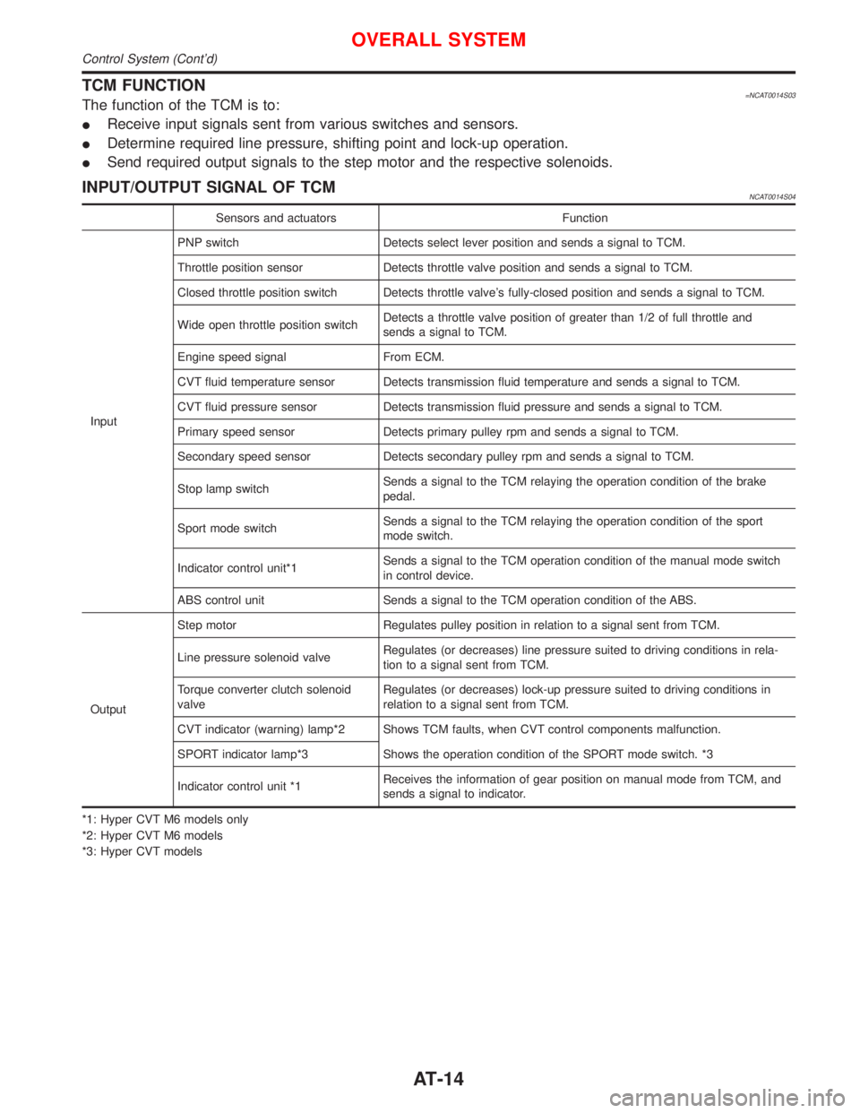
TCM FUNCTION=NCAT0014S03The function of the TCM is to:
IReceive input signals sent from various switches and sensors.
IDetermine required line pressure, shifting point and lock-up operation.
ISend required output signals to the step motor and the respective solenoids.
INPUT/OUTPUT SIGNAL OF TCMNCAT0014S04
Sensors and actuators Function
InputPNP switch Detects select lever position and sends a signal to TCM.
Throttle position sensor Detects throttle valve position and sends a signal to TCM.
Closed throttle position switch Detects throttle valve's fully-closed position and sends a signal to TCM.
Wide open throttle position switchDetects a throttle valve position of greater than 1/2 of full throttle and
sends a signal to TCM.
Engine speed signal From ECM.
CVT fluid temperature sensor Detects transmission fluid temperature and sends a signal to TCM.
CVT fluid pressure sensor Detects transmission fluid pressure and sends a signal to TCM.
Primary speed sensor Detects primary pulley rpm and sends a signal to TCM.
Secondary speed sensor Detects secondary pulley rpm and sends a signal to TCM.
Stop lamp switchSends a signal to the TCM relaying the operation condition of the brake
pedal.
Sport mode switchSends a signal to the TCM relaying the operation condition of the sport
mode switch.
Indicator control unit*1Sends a signal to the TCM operation condition of the manual mode switch
in control device.
ABS control unit Sends a signal to the TCM operation condition of the ABS.
OutputStep motor Regulates pulley position in relation to a signal sent from TCM.
Line pressure solenoid valveRegulates (or decreases) line pressure suited to driving conditions in rela-
tion to a signal sent from TCM.
Torque converter clutch solenoid
valveRegulates (or decreases) lock-up pressure suited to driving conditions in
relation to a signal sent from TCM.
CVT indicator (warning) lamp*2 Shows TCM faults, when CVT control components malfunction.
SPORT indicator lamp*3 Shows the operation condition of the SPORT mode switch. *3
Indicator control unit *1Receives the information of gear position on manual mode from TCM, and
sends a signal to indicator.
*1: Hyper CVT M6 models only
*2: Hyper CVT M6 models
*3: Hyper CVT models
OVERALL SYSTEM
Control System (Cont'd)
AT-14
Page 17 of 2267
IntroductionNCAT0017The CVT system has two self-diagnostic systems.
The first is the emission-related on board diagnostic system (OBD) performed by the TCM in combination with
the ECM. The malfunction is indicated by the MI (malfunction indicator) and is stored as a DTC in the ECM
memory but not the TCM memory.
The second is the TCM original self-diagnosis indicated by the CVT indicator (warning) lamp or SPORT indi-
cator lamp. The malfunction is stored in the TCM memory. The detected items are overlapped with OBD self-
diagnostic items. For detail, refer to AT-26.
OBD Function for CVT SystemNCAT0018The ECM provides emission-related on board diagnostic (OBD) functions for the CVT system. One function
is to receive a signal from the TCM used with OBD-related parts of the CVT system. The signal is sent to the
ECM when a malfunction occurs in the corresponding OBD-related part. The other function is to indicate a
diagnostic result by means of the MI (malfunction indicator) on the instrument panel. Sensors, switches and
solenoid valves are used as sensing elements.
The MI automatically illuminates in Two Trip Detection Logic when a malfunction is sensed in relation to CVT
system parts.
OBD Diagnostic Trouble Code (DTC)NCAT0020HOW TO READ DTC AND 1ST TRIP DTCNCAT0020S01DTC and 1st trip DTC can be read by the following methods.
1.(
No Tools)The number of blinks of the malfunction indicator in the Diagnostic Test Mode II (Self-Di-
agnostic Results) Examples: 0705, 0710, 0715, 0720, etc. For details, refer to EC section [ªMalfunction
Indicator (MI)º, ªON BOARD DIAGNOSTIC SYSTEM DESCRIPTIONº].
These DTCs are controlled by NISSAN.
2.(
with CONSULT-II orGST)CONSULT-II or GST (Generic Scan Tool) Examples: P0705, P0710,
P0720, P0725, etc.
These DTCs are prescribed by ISO15031-6.
(CONSULT-II also displays the malfunctioning component or system.)
I1st trip DTC No. is the same as DTC No.
IOutput of the diagnostic trouble code indicates that the indicated circuit has a malfunction.
However, in case of the Mode II and GST they do not indicate whether the malfunction is still
occurring or occurred in the past and returned to normal.
CONSULT-II can identify them as shown below. Therefore, using CONSULT-II (if available) is rec-
ommended.
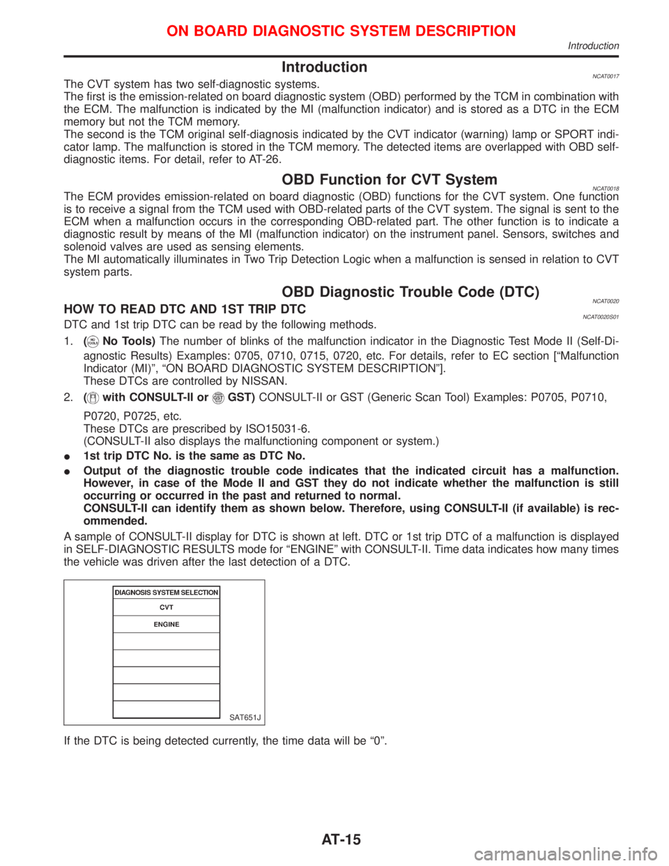
A sample of CONSULT-II display for DTC is shown at left. DTC or 1st trip DTC of a malfunction is displayed
in SELF-DIAGNOSTIC RESULTS mode for ªENGINEº with CONSULT-II. Time data indicates how many times
the vehicle was driven after the last detection of a DTC.
If the DTC is being detected currently, the time data will be ª0º.
SAT651J
ON BOARD DIAGNOSTIC SYSTEM DESCRIPTION
Introduction
AT-15
Page 22 of 2267
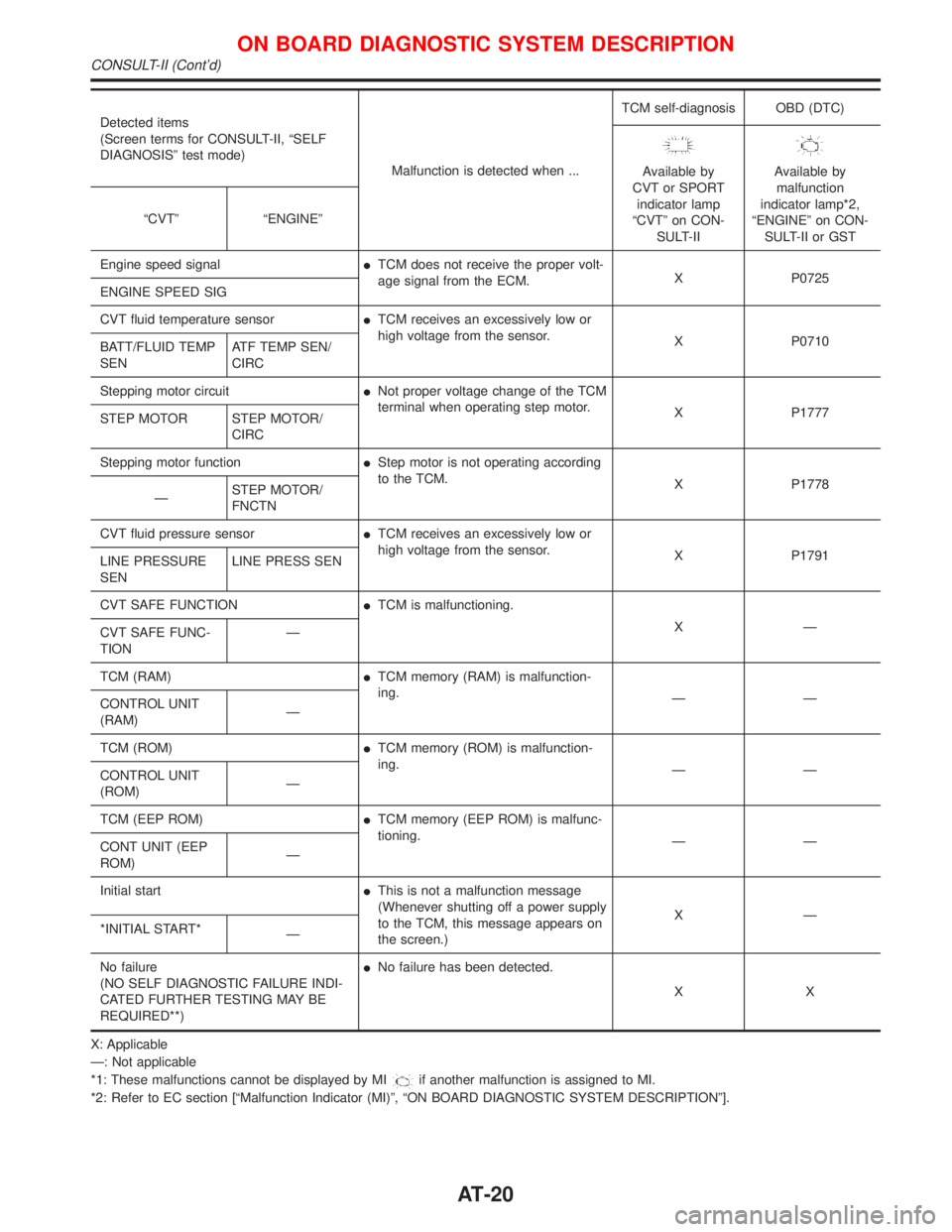
Detected items
(Screen terms for CONSULT-II, ªSELF
DIAGNOSISº test mode)
Malfunction is detected when ...TCM self-diagnosis OBD (DTC)
Available by
CVT or SPORT
indicator lamp
ªCVTº on CON-
SULT-IIAvailable by
malfunction
indicator lamp*2,
ªENGINEº on CON-
SULT-II or GST ªCVTº ªENGINEº
Engine speed signalITCM does not receive the proper volt-
age signal from the ECM.X P0725
ENGINE SPEED SIG
CVT fluid temperature sensorITCM receives an excessively low or
high voltage from the sensor.
X P0710
BATT/FLUID TEMP
SENATF TEMP SEN/
CIRC
Stepping motor circuitINot proper voltage change of the TCM
terminal when operating step motor.
X P1777
STEP MOTOR STEP MOTOR/
CIRC
Stepping motor functionIStep motor is not operating according
to the TCM.
X P1778
ÐSTEP MOTOR/
FNCTN
CVT fluid pressure sensorITCM receives an excessively low or
high voltage from the sensor.
X P1791
LINE PRESSURE
SENLINE PRESS SEN
CVT SAFE FUNCTIONITCM is malfunctioning.
XÐ
CVT SAFE FUNC-
TIONÐ
TCM (RAM)ITCM memory (RAM) is malfunction-
ing.
ÐÐ
CONTROL UNIT
(RAM)Ð
TCM (ROM)ITCM memory (ROM) is malfunction-
ing.
ÐÐ
CONTROL UNIT
(ROM)Ð
TCM (EEP ROM)ITCM memory (EEP ROM) is malfunc-
tioning.
ÐÐ
CONT UNIT (EEP
ROM)Ð
Initial startIThis is not a malfunction message
(Whenever shutting off a power supply
to the TCM, this message appears on
the screen.)XÐ
*INITIAL START*
Ð
No failure
(NO SELF DIAGNOSTIC FAILURE INDI-
CATED FURTHER TESTING MAY BE
REQUIRED**)INo failure has been detected.
XX
X: Applicable
Ð: Not applicable
*1: These malfunctions cannot be displayed by MI
if another malfunction is assigned to MI.
*2: Refer to EC section [ªMalfunction Indicator (MI)º, ªON BOARD DIAGNOSTIC SYSTEM DESCRIPTIONº].
ON BOARD DIAGNOSTIC SYSTEM DESCRIPTION
CONSULT-II (Cont'd)
AT-20
Page 24 of 2267
Item DisplayMonitor item
Description Remarks
TCM input
signalsMain
signals
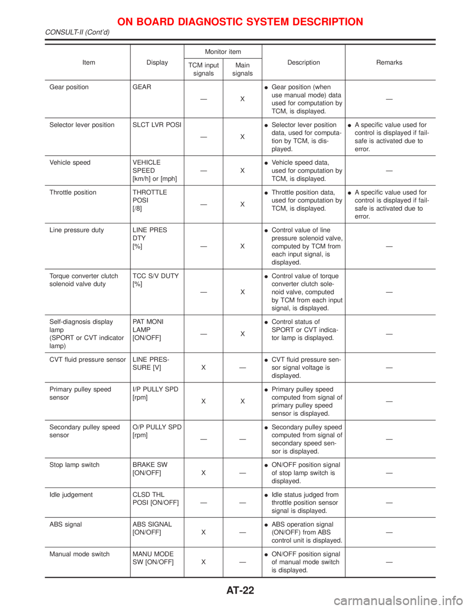
Gear position GEAR
ÐXIGear position (when
use manual mode) data
used for computation by
TCM, is displayed.Ð
Selector lever position SLCT LVR POSI
ÐXISelector lever position
data, used for computa-
tion by TCM, is dis-
played.IA specific value used for
control is displayed if fail-
safe is activated due to
error.
Vehicle speed VEHICLE
SPEED
[km/h] or [mph]ÐXIVehicle speed data,
used for computation by
TCM, is displayed.Ð
Throttle position THROTTLE
POSI
[/8]ÐXIThrottle position data,
used for computation by
TCM, is displayed.IA specific value used for
control is displayed if fail-
safe is activated due to
error.
Line pressure duty LINE PRES
DTY
[%] Ð XIControl value of line
pressure solenoid valve,
computed by TCM from
each input signal, is
displayed.Ð
Torque converter clutch
solenoid valve dutyTCC S/V DUTY
[%]
ÐXIControl value of torque
converter clutch sole-
noid valve, computed
by TCM from each input
signal, is displayed.Ð
Self-diagnosis display
lamp
(SPORT or CVT indicator
lamp)PAT MONI
LAMP
[ON/OFF]ÐXIControl status of
SPORT or CVT indica-
tor lamp is displayed.Ð
CVT fluid pressure sensor LINE PRES-
SURE [V] X ÐICVT fluid pressure sen-
sor signal voltage is
displayed.Ð
Primary pulley speed
sensorI/P PULLY SPD
[rpm]
XXIPrimary pulley speed
computed from signal of
primary pulley speed
sensor is displayed.Ð
Secondary pulley speed
sensorO/P PULLY SPD
[rpm]
ÐÐISecondary pulley speed
computed from signal of
secondary speed sen-
sor is displayed.Ð
Stop lamp switch BRAKE SW
[ON/OFF] X ÐION/OFF position signal
of stop lamp switch is
displayed.Ð
Idle judgement CLSD THL
POSI [ON/OFF] Ð ÐIIdle status judged from
throttle position sensor
signal is displayed.Ð
ABS signal ABS SIGNAL
[ON/OFF] X ÐIABS operation signal
(ON/OFF) from ABS
control unit is displayed.Ð
Manual mode switch MANU MODE
SW [ON/OFF] X ÐION/OFF position signal
of manual mode switch
is displayed.Ð
ON BOARD DIAGNOSTIC SYSTEM DESCRIPTION
CONSULT-II (Cont'd)
AT-22
Page 25 of 2267
![NISSAN PRIMERA 1999 Electronic Repair Manual Item DisplayMonitor item
Description Remarks
TCM input
signalsMain
signals
Non-manual mode switch NON M MODE
SW [ON/OFF] X ÐION/OFF position signal
of non-manual mode
switch is displayed.Ð
Up switch NISSAN PRIMERA 1999 Electronic Repair Manual Item DisplayMonitor item
Description Remarks
TCM input
signalsMain
signals
Non-manual mode switch NON M MODE
SW [ON/OFF] X ÐION/OFF position signal
of non-manual mode
switch is displayed.Ð
Up switch](/manual-img/5/57377/w960_57377-24.png)
Item DisplayMonitor item
Description Remarks
TCM input
signalsMain
signals
Non-manual mode switch NON M MODE
SW [ON/OFF] X ÐION/OFF position signal
of non-manual mode
switch is displayed.Ð
Up switch UP SW
[ON/OFF] X ÐION/OFF position signal
of up switch is dis-
played.Ð
Down switch DOWN SW
[ON/OFF] X ÐION/OFF position signal
of down switch is dis-
played.Ð
Step motor coil A S/M COIL [A]
[ON/OFF]
ÐÐIControl valve of step
motor coil A, computed
by TCM from each input
signal is displayed.Ð
Step motor coil B S/M COIL [B]
[ON/OFF]
ÐÐIControl valve of step
motor coil B, computed
by TCM from each input
signal is displayed.Ð
Step motor coil C S/M COIL [C]
[ON/OFF]
ÐÐIControl valve of step
motor coil C, computed
by TCM from each input
signal is displayed.Ð
Step motor coil D S/M COIL [D]
[ON/OFF]
ÐÐIControl valve of step
motor coil D, computed
by TCM from each input
signal is displayed.Ð
CVT ratio CVT RATIO [Ð]
ÐXIReal CVT ratio operated
TCM is displayed.Ð
Step PLY CONT
STEP [step]ÐXIStep motor position is
displayed.Ð
Line pressure LINE PRES-
SURE [MPa]
ÐXIReal line pressure cal-
culated from line pres-
sure sensor voltage
with TCM is displayed.Ð
Pulley rpm×in 2 T RPM [rpm]
ÐÐITarget primary pulley
speed operated with
TCM is displayed.Ð
CVT ratio 2 T RATIO [Ð]
ÐÐITarget changing the
speed ratio operated
with TCM is displayed.Ð
Step 2 T STEP [step]
ÐÐITarget step motor posi-
tion operated with TCM
is displayed.Ð
X: Applicable
Ð: Not applicable
ON BOARD DIAGNOSTIC SYSTEM DESCRIPTION
CONSULT-II (Cont'd)
AT-23
Page 27 of 2267
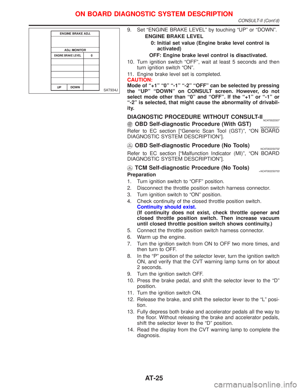
9. Set ªENGINE BRAKE LEVELº by touching ªUPº or ªDOWNº.
ENGINE BRAKE LEVEL
0: Initial set value (Engine brake level control is
activated)
OFF: Engine brake level control is disactivated.
10. Turn ignition switch ªOFFº, wait at least 5 seconds and then
turn ignition switch ªONº.
11. Engine brake level set is completed.
CAUTION:
Mode of ª+1º ª0º ª-1º ª-2º ªOFFº can be selected by pressing
the ªUPº ªDOWNº on CONSULT screen. However, do not
select mode other than ª0º and ªOFFº. If the ª+1º or ª-1º or
ª-2º is selected, that might cause the abnormality of drivabil-
ity.
DIAGNOSTIC PROCEDURE WITHOUT CONSULT-IINCAT0022S07OBD Self-diagnostic Procedure (With GST)NCAT0022S0701Refer to EC section [ªGeneric Scan Tool (GST)º, ªON BOARD
DIAGNOSTIC SYSTEM DESCRIPTIONº].
OBD Self-diagnostic Procedure (No Tools)NCAT0022S0702
Refer to EC section [ªMalfunction Indicator (MI)º, ªON BOARD
DIAGNOSTIC SYSTEM DESCRIPTIONº].
TCM Self-diagnostic Procedure (No Tools)=NCAT0022S0703Preparation
1. Turn ignition switch to ªOFFº position.
2. Disconnect the throttle position switch harness connector.
3. Turn ignition switch to ªONº position.
4. Check continuity of the closed throttle position switch.
Continuity should exist.
(If continuity does not exist, check throttle opener and
closed throttle position switch. Then increase vacuum
until closed throttle position switch shows continuity.)
5. Connect the throttle position switch harness connector.
6. Warm up the engine.
7. Turn the ignition switch from ON to OFF two more times, and
then turn to OFF.
8. In the ªPº position of the selector lever, turn the ignition switch
ON, and verify that the CVT warning lamp turns on for about
2 seconds.
9. Turn the ignition switch OFF.
10. Press the brake pedal, and shift the selector lever to the ªDº
position.
11. Turn the ignition switch ON.
12. Release the brake, and shift the selector lever to the ªLº posi-
tion.
13. Fully depress both brake and accelerator pedals all the way to
the floor. Without releasing the brake and accelerator pedals,
shift the selector lever to the ªDº position.
14. Read the display from the CVT warning lamp to complete the
diagnosis.
SAT934J
ON BOARD DIAGNOSTIC SYSTEM DESCRIPTION
CONSULT-II (Cont'd)
AT-25
Page 31 of 2267
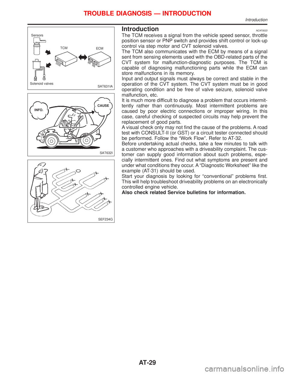
IntroductionNCAT0023
The TCM receives a signal from the vehicle speed sensor, throttle
position sensor or PNP switch and provides shift control or lock-up
control via step motor and CVT solenoid valves.
The TCM also communicates with the ECM by means of a signal
sent from sensing elements used with the OBD-related parts of the
CVT system for malfunction-diagnostic purposes. The TCM is
capable of diagnosing malfunctioning parts while the ECM can
store malfunctions in its memory.
Input and output signals must always be correct and stable in the
operation of the CVT system. The CVT system must be in good
operating condition and be free of valve seizure, solenoid valve
malfunction, etc.
It is much more difficult to diagnose a problem that occurs intermit-
tently rather than continuously. Most intermittent problems are
caused by poor electric connections or improper wiring. In this
case, careful checking of suspected circuits may help prevent the
replacement of good parts.
A visual check only may not find the cause of the problems. A road
test with CONSULT-II (or GST) or a circuit tester connected should
be performed. Follow the ªWork Flowº. Refer to AT-32.
Before undertaking actual checks, take a few minutes to talk with
a customer who approaches with a driveability complaint. The cus-
tomer can supply good information about such problems, espe-
cially intermittent ones. Find out what symptoms are present and
under what conditions they occur. A ªDiagnostic Worksheetº like the
example (AT-31) should be used.
Start your diagnosis by looking for ªconventionalº problems first.
This will help troubleshoot driveability problems on an electronically
controlled engine vehicle.
Also check related Service bulletins for information.
SAT631IA Sensors
TCM
ECM
Solenoid valves
SAT632I INFO.CAUSE
SEF234G
TROUBLE DIAGNOSIS Ð INTRODUCTION
Introduction
AT-29
Page 44 of 2267
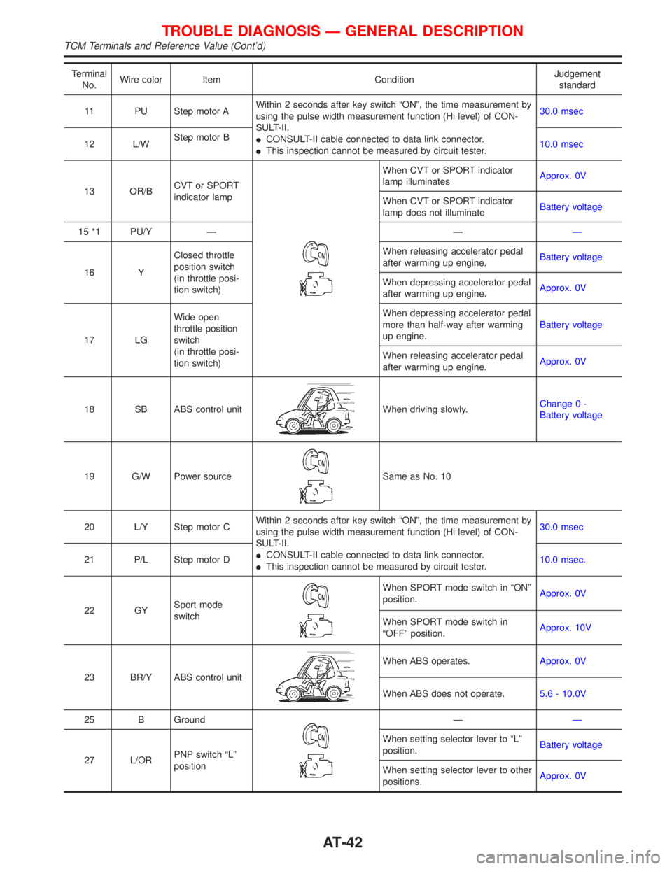
Terminal
No.Wire color Item ConditionJudgement
standard
11 PU Step motor AWithin 2 seconds after key switch ªONº, the time measurement by
using the pulse width measurement function (Hi level) of CON-
SULT-II.
ICONSULT-II cable connected to data link connector.
IThis inspection cannot be measured by circuit tester.30.0 msec
12 L/WStep motor B
10.0 msec
13 OR/BCVT or SPORT
indicator lamp
When CVT or SPORT indicator
lamp illuminatesApprox. 0V
When CVT or SPORT indicator
lamp does not illuminateBattery voltage
15 *1 PU/Y Ð ÐÐ
16 YClosed throttle
position switch
(in throttle posi-
tion switch)When releasing accelerator pedal
after warming up engine.Battery voltage
When depressing accelerator pedal
after warming up engine.Approx. 0V
17 LGWide open
throttle position
switch
(in throttle posi-
tion switch)When depressing accelerator pedal
more than half-way after warming
up engine.Battery voltage
When releasing accelerator pedal
after warming up engine.Approx. 0V
18 SB ABS control unit
When driving slowly.Change 0 -
Battery voltage
19 G/W Power source
Same as No. 10
20 L/Y Step motor CWithin 2 seconds after key switch ªONº, the time measurement by
using the pulse width measurement function (Hi level) of CON-
SULT-II.
ICONSULT-II cable connected to data link connector.
IThis inspection cannot be measured by circuit tester.30.0 msec
21 P/L Step motor D10.0 msec.
22 GYSport mode
switch
When SPORT mode switch in ªONº
position.Approx. 0V
When SPORT mode switch in
ªOFFº position.Approx. 10V
23 BR/Y ABS control unit
When ABS operates.Approx. 0V
When ABS does not operate.5.6 - 10.0V
25 B Ground
ÐÐ
27 L/ORPNP switch ªLº
positionWhen setting selector lever to ªLº
position.Battery voltage
When setting selector lever to other
positions.Approx. 0V
TROUBLE DIAGNOSIS Ð GENERAL DESCRIPTION
TCM Terminals and Reference Value (Cont'd)
AT-42