Page 45 of 2267

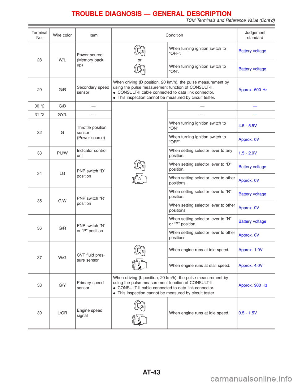
Terminal
No.Wire color Item ConditionJudgement
standard
28 W/LPower source
(Memory back-
up)
or
When turning ignition switch to
ªOFFº.Battery voltage
When turning ignition switch to
ªONº.Battery voltage
29 G/RSecondary speed
sensorWhen driving (D position, 20 km/h), the pulse measurement by
using the pulse measurement function of CONSULT-II.
ICONSULT-II cable connected to data link connector.
IThis inspection cannot be measured by circuit tester.Approx. 600 Hz
30 *2 G/B Ð
ÐÐ
31 *2 GY/L Ð ÐÐ
32 GThrottle position
sensor
(Power source)When turning ignition switch to
ªONº4.5 - 5.5V
When turning ignition switch to
ªOFFºApprox. 0V
33 PU/WIndicator control
unitWhen setting selector lever to any
position.1.5 - 2.0V
34 LGPNP switch ªDº
positionWhen setting selector lever to ªDº
position.Battery voltage
When setting selector lever to other
positions.Approx. 0V
35 G/WPNP switch ªRº
positionWhen setting selector lever to ªRº
position.Battery voltage
When setting selector lever to other
positions.Approx. 0V
36 G/RPNP switch ªNº
or ªPº positionWhen setting selector lever to ªNº
or ªPº position.Battery voltage
When setting selector lever to other
positions.Approx. 0V
37 W/GCVT fluid pres-
sure sensor
When engine runs at idle speed.Approx. 1.0V
When engine runs at stall speed.Approx. 4.0V
38 G/YPrimary speed
sensorWhen driving (L position, 20 km/h), the pulse measurement by
using the pulse measurement function of CONSULT-II.
ICONSULT-II cable connected to data link connector.
IThis inspection cannot be measured by circuit tester.Approx. 900 Hz
39 L/OREngine speed
signal
When engine runs at idle speed.0.5 - 1.5V
TROUBLE DIAGNOSIS Ð GENERAL DESCRIPTION
TCM Terminals and Reference Value (Cont'd)
AT-43
Page 47 of 2267
Wiring Diagram Ð CVT Ð MAINNCAT0031
YAT201
BATTERY
ENGINE
CONTROL
MODULE
RELAY
OFFONSTOP
LAMP
SWITCH
FUSE
BLOCK
(J/B)OFFONSTOP
LAMP
SWITCH: Detectable line for DTC
: Non-detectable line for DTC
: LHD models
: RHD models Refer to EL-POWER. FUSE
BLOCK
(J/B)
TCM
(TRANSMISSION
CONTROL
MODULE)
Refer to last page
(foldout page). ECM
TROUBLE DIAGNOSIS FOR POWER SUPPLY
Wiring Diagram Ð CVT Ð MAIN
AT-45
Page 55 of 2267
Component Inspection=NCAT0034PARK/NEUTRAL POSITION SWITCHNCAT0034S011. Check continuity between terminals 1 and 2 and between ter-
minals 3 and 5, 6, 7, 8, 9 while moving manual shaft through
each position.
Lever position Terminal No.
P 3Ð7 1Ð2
R 3Ð8
N 3Ð9 1Ð2
D 3Ð6
L 3Ð5
2. If NG, check again with control cable disconnected from
manual shaft of CVT assembly. Refer to step 1.
3. If OK on step 2, adjust control cable. Refer to AT-114.
4. If NG on step 2, remove PNP switch from CVT and check
continuity of PNP switch terminals. Refer to step 1.
5. If OK on step 4, adjust PNP switch. Refer to AT-114.
6. If NG on step 4, replace PNP switch.
DTC P0705 PARK/NEUTRAL POSITION (PNP) SWITCH
Component Inspection
AT-53
Page 58 of 2267
Wiring Diagram Ð AT Ð FTSNCAT0200
YAT203
CONTROL VALVE
(CVT FLUID
TEMPERATURE
SENSOR)
: Detectable line for DTC
: Non-detectable line for DTC
TCM
(TRANSMISSION
CONTROL MODULE)ECM
DTC P0710 CVT FLUID TEMPERATURE SENSOR CIRCUIT
Wiring Diagram Ð AT Ð FTS
AT-56
Page 62 of 2267
Wiring Diagram Ð AT Ð VSSA/TNCAT0221
YAT204
PRIMARY
SPEED
SENSOR
: Detectable line for DTC
: Non-detectable line for DTC
TCM
(TRANSMISSION
CONTROL MODULE)ECM
DTC P0715 PRIMARY SPEED SENSOR
Wiring Diagram Ð AT Ð VSSA/T
AT-60
Page 66 of 2267
Wiring Diagram Ð AT Ð VSSA/TNCAT0201
YAT205
SECONDARY
SPEED
SENSOR
: Detectable line for DTC
: Non-detectable line for DTC
TCM
(TRANSMISSION
CONTROL
MODULE)ECM
DTC P0720 VEHICLE SPEED SENSOR CVT (SECONDARY SPEED SENSOR)
Wiring Diagram Ð AT Ð VSSA/T
AT-64
Page 69 of 2267
Wiring Diagram Ð AT Ð ENGSSNCAT0202
YAT206
ECM
: Detectable line for DTC
: Non-detectable line for DTC
TCM
(TRANSMISSION
CONTROL MODULE)
DTC P0725 ENGINE SPEED SIGNAL
Wiring Diagram Ð AT Ð ENGSS
AT-67
Page 70 of 2267

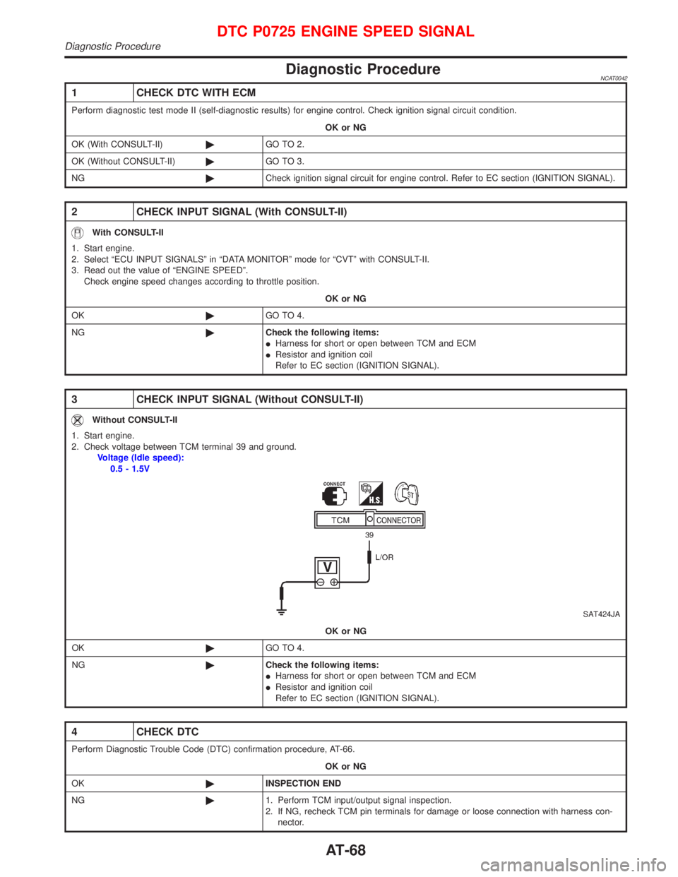
Diagnostic ProcedureNCAT0042
1 CHECK DTC WITH ECM
Perform diagnostic test mode II (self-diagnostic results) for engine control. Check ignition signal circuit condition.
OK or NG
OK (With CONSULT-II)©GO TO 2.
OK (Without CONSULT-II)©GO TO 3.
NG©Check ignition signal circuit for engine control. Refer to EC section (IGNITION SIGNAL).
2 CHECK INPUT SIGNAL (With CONSULT-II)
With CONSULT-II
1. Start engine.
2. Select ªECU INPUT SIGNALSº in ªDATA MONITORº mode for ªCVTº with CONSULT-II.
3. Read out the value of ªENGINE SPEEDº.
Check engine speed changes according to throttle position.
OK or NG
OK©GO TO 4.
NG©Check the following items:
IHarness for short or open between TCM and ECM
IResistor and ignition coil
Refer to EC section (IGNITION SIGNAL).
3 CHECK INPUT SIGNAL (Without CONSULT-II)
Without CONSULT-II
1. Start engine.
2. Check voltage between TCM terminal 39 and ground.
Voltage (Idle speed):
0.5 - 1.5V
SAT424JA
OK or NG
OK©GO TO 4.
NG©Check the following items:
IHarness for short or open between TCM and ECM
IResistor and ignition coil
Refer to EC section (IGNITION SIGNAL).
4 CHECK DTC
Perform Diagnostic Trouble Code (DTC) confirmation procedure, AT-66.
OK or NG
OK©INSPECTION END
NG©1. Perform TCM input/output signal inspection.
2. If NG, recheck TCM pin terminals for damage or loose connection with harness con-
nector.
DTC P0725 ENGINE SPEED SIGNAL
Diagnostic Procedure
AT-68