1999 NISSAN PRIMERA Control
[x] Cancel search: ControlPage 119 of 2267
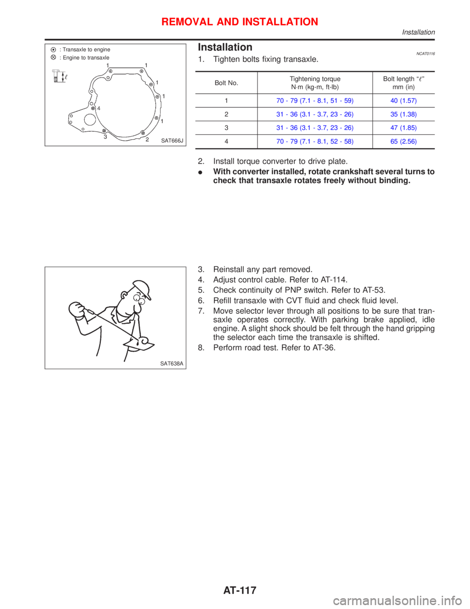
InstallationNCAT01161. Tighten bolts fixing transaxle.
Bolt No.Tightening torque
N×m (kg-m, ft-lb)Bolt length ªº
mm (in)
170 - 79 (7.1 - 8.1, 51 - 59) 40 (1.57)
231 - 36 (3.1 - 3.7, 23 - 26) 35 (1.38)
331 - 36 (3.1 - 3.7, 23 - 26) 47 (1.85)
470 - 79 (7.1 - 8.1, 52 - 58) 65 (2.56)
2. Install torque converter to drive plate.
IWith converter installed, rotate crankshaft several turns to
check that transaxle rotates freely without binding.
3. Reinstall any part removed.
4. Adjust control cable. Refer to AT-114.
5. Check continuity of PNP switch. Refer to AT-53.
6. Refill transaxle with CVT fluid and check fluid level.
7. Move selector lever through all positions to be sure that tran-
saxle operates correctly. With parking brake applied, idle
engine. A slight shock should be felt through the hand gripping
the selector each time the transaxle is shifted.
8. Perform road test. Refer to AT-36.
SAT666J : Transaxle to engine
: Engine to transaxle
SAT638A
REMOVAL AND INSTALLATION
Installation
AT-117
Page 120 of 2267
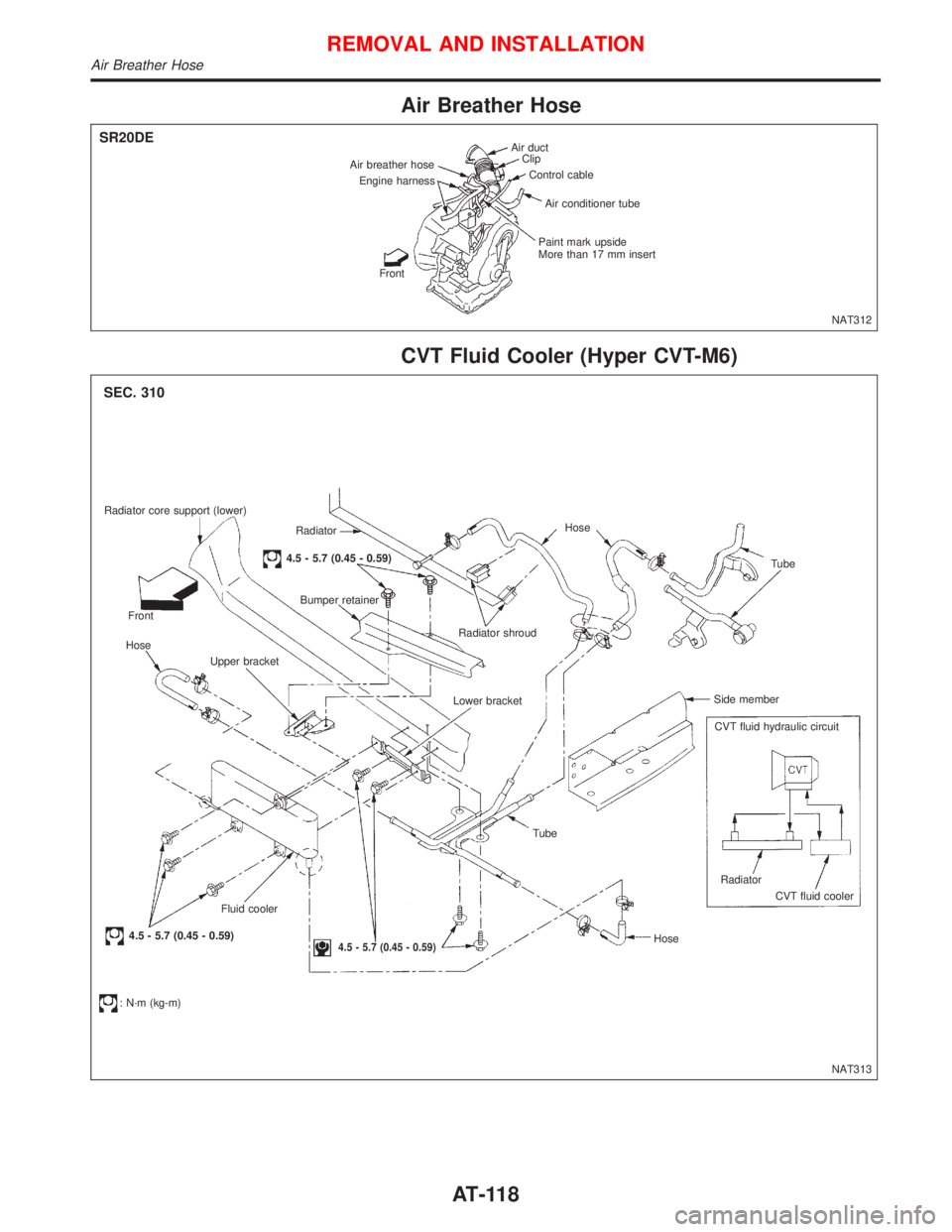
Air Breather Hose
CVT Fluid Cooler (Hyper CVT-M6)
Air duct
Clip
Control cable
Air conditioner tube
Paint mark upside
More than 17 mm insert
Front Engine harness Air breather hose
NAT312
SR20DE
Radiator core support (lower)
Radiator
4.5 - 5.7 (0.45 - 0.59)
Bumper retainer
Front
Hose
Upper bracket
Fluid cooler
4.5 - 5.7 (0.45 - 0.59)
: N´m (kg-m)
4.5 - 5.7 (0.45 - 0.59)
Tube
HoseRadiator
CVT fluid cooler CVT fluid hydraulic circuit Side memberTube Hose
Radiator shroud
Lower bracket
NAT313
SEC. 310
REMOVAL AND INSTALLATION
Air Breather Hose
AT-118
Page 123 of 2267
BRAKE SYSTEM
SECTION
BR
CONTENTS
PRECAUTIONS............................................................. 3
Supplemental Restraint System (SRS)²AIR
BAG²and²SEAT BELT PRE-TENSIONER²............. 3
Precautions for Brake System ................................... 3
Precautions When Working On ABS ......................... 4
Wiring Diagrams and Trouble Diagnosis ................... 4
PRECAUTIONS AND PREPARATION.......................... 5
Commercial Service Tools ......................................... 5
NOISE, VIBRATION AND HARSHNESS (NVH)
TROUBLE SHOOTING.................................................. 6
NVH Troubleshooting Chart....................................... 6
CHECK AND ADJUSTMENT........................................ 7
Checking Brake Fluid Level....................................... 7
Checking Brake Line ................................................. 7
Changing Brake Fluid ................................................ 7
Brake Burnishing Procedure...................................... 7
Bleeding Brake System ............................................. 8
BRAKE HYDRAULIC LINE........................................... 9
Removal ................................................................... 10
Inspection................................................................. 10
Installation ................................................................ 10
CONTROL VALVE........................................................ 11
Dual Proportioning Valve .......................................... 11
BRAKE PEDAL AND BRACKET................................ 13
Removal and Installation ......................................... 13
Inspection................................................................. 13
Adjustment ............................................................... 13
MASTER CYLINDER................................................... 15
Removal ................................................................... 15
Disassembly............................................................. 15
Inspection................................................................. 16
Assembly ................................................................. 16
Installation ................................................................ 17BRAKE BOOSTER...................................................... 18
On-vehicle Service................................................... 18
Removal ................................................................... 18
Inspection................................................................. 19
Installation ................................................................ 19
VACUUM HOSE........................................................... 20
Removal and Installation ......................................... 21
Inspection................................................................. 21
FRONT DISC BRAKE................................................. 23
Pad Replacement .................................................... 23
Removal ................................................................... 24
Disassembly............................................................. 25
Inspection - Caliper.................................................. 25
SR20DE - M/T
FRONT DISC BRAKE................................................. 26
Pad Replacement .................................................... 26
Installation ................................................................ 28
Removal ................................................................... 29
Disassembly............................................................. 29
Inspection - Caliper.................................................. 29
FRONT DISC BRAKE................................................. 31
Inspection - Rotor .................................................... 31
Assembly ................................................................. 31
Installation ................................................................ 32
REAR DISC BRAKE TYPE 1...................................... 33
Component .............................................................. 33
Pad Replacement .................................................... 33
Removal ................................................................... 35
Disassembly............................................................. 35
BR
Page 124 of 2267
Inspection................................................................. 36
Assembly ................................................................. 37
Installation ................................................................ 39
REAR DISC BRAKE TYPE 2...................................... 40
Component .............................................................. 40
Pad Replacement .................................................... 40
Removal ................................................................... 42
Disassembly............................................................. 42
Inspection................................................................. 42
Installation ................................................................ 43
REAR DRUM BRAKE................................................. 44
Components............................................................. 44
Removal ................................................................... 44
Inspection - Wheel Cylinder .................................... 45
Wheel Cylinder Overhaul......................................... 46
Inspection - Drum .................................................... 46
Inspection - Lining ................................................... 46
Installation ................................................................ 46
PARKING BRAKE CONTROL.................................... 48
Removal and Installation ......................................... 48
Inspection................................................................. 49
Adjustment ............................................................... 49
ANTI-LOCK BRAKE SYSTEM.................................... 50
Purpose.................................................................... 50
Operation ................................................................. 50
ABS Hydraulic Circuit .............................................. 50
System Components ............................................... 51
System Description .................................................. 51
Removal and Installation ......................................... 53
TROUBLE DIAGNOSES............................................. 57
How to Perform Trouble Diagnoses for Quick
and Accurate Repair ................................................ 57
Preliminary Check.................................................... 59
Component Parts and Harness Connector
Location ................................................................... 60
Circuit Diagram for Quick Pinpoint Check............... 61Wiring Diagram - ABS - ........................................... 62
Self-diagnosis (Only models with data link
connector terminal No. 8) ........................................ 67
TROUBLE DIAGNOSIS - GENERAL
DESCRIPTION............................................................. 69
CONSULT-II ............................................................. 69
CONSULT-II Inspection Procedure.......................... 70
Ground Circuit Check .............................................. 75
TROUBLE DIAGNOSIS - GENERAL
DESCRIPTION............................................................. 76
Malfunction Code/Symptom Chart........................... 76
TROUBLE DIAGNOSES FOR SELF-DIAGNOSTIC
ITEMS........................................................................... 77
Diagnostic Procedure 1 (Wheel sensor or rotor) .... 77
Diagnostic Procedure 2 (ABS actuator solenoid
valve and solenoid valve relay) ............................... 79
Diagnostic Procedure 3 (Motor Relay or motor) ..... 81
Diagnostic Procedure 4 (Low voltage) .................... 83
Diagnostic Procedure 5 (Control unit) ..................... 84
TROUBLE DIAGNOSES FOR SYMPTOMS............... 85
Diagnostic Procedure 6 (ABS works frequently) ..... 85
Diagnostic Procedure 7 (Unexpected pedal
action) ...................................................................... 86
Diagnostic Procedure 8 (Long stopping distance) .. 86
Diagnostic Procedure 9 (ABS does not work.) ....... 87
Diagnostic Procedure 10 (Pedal vibration and
noise) ....................................................................... 87
Diagnostic Procedure 11 (ABS Warning lamp
does not come on when ignition switch is turned
ON) .......................................................................... 88
Diagnostic Procedure 12 (Warning lamp stays on
when ignition switch is turned ON).......................... 90
SERVICE DATA AND SPECIFICATIONS (SDS)........ 91
General Specifications ............................................. 91
Inspection and Adjustment ...................................... 92
When you read wiring diagrams:
lRead GI section, ªHOW TO READ WIRING DIAGRAMSº.
lSee EL section, ªPOWER SUPPLY ROUTINGº for power distribution circuit.
lSee EL section for NATS information and wiring diagram.
When you perform trouble diagnoses, read GI section, ªHOW TO FOLLOW FLOW
CHART IN TROUBLE DIAGNOSESº and ªHOW TO PERFORM EFFICIENT DIAGNOSIS
FOR AN ELECTRICAL INCIDENTº.
BR-2
Page 126 of 2267
Precautions When Working On ABS
lUse recommended tyres in combination with ABS.
lInstall tyres or studded tyres, etc. with the same size.
lIf different sizes of tyres, or tyres other than the ones
recommended for use with the ABS, are fitted, stopping
distance will increase and control and stability could
deteriorate.
lWhen changing brake pads, use Nissan genuine parts.
lWhen fitting radios etc, do not position the radio unit,
antenna, or antenna cables within an area of about 100
mm (3.94 in) of the control unit.
lWhen doing any work that requires electro-welding, first
remove the control unit.
lMake sure when taking a power supply for the audio,
lamps etc., not to take this from any ABS-related har-
ness. (Refer to the electrical wiring diagrams for ABS-
related harnesses)
Wiring Diagrams and Trouble Diagnosis
When you read wiring diagrams, refer to the following:
lGI-11, ªHOW TO READ WIRING DIAGRAMSº
lEL-10, ªPOWER SUPPLY ROUTINGº
When you perform trouble diagnosis, refer to the following:
lGI-35, ªHOW TO FOLLOW TEST GROUPS IN TROUBLE DIAGNOSISº
lGI-24, ªHOW TO PERFORM EFFICIENT DIAGNOSES FOR AN ELECTRICAL INCIDENTº
PRECAUTIONS
BR-4
Page 133 of 2267
Dual Proportioning Valve
INSPECTION
CAUTION:
lCarefully monitor brake fluid level at master cylinder.
lUse new brake fluid ªDOT 4º.
lBe careful not to splash brake fluid on painted areas; it
may cause paint damage. If brake fluid is splashed on
paint areas, wash it away with water immediately.
lDepress pedal slowly when raising front brake pressure.
lCheck rear brake pressure at least 2 seconds after front
brake pressure reaches specified value.
1. Connect brake fluid pressure gauge to air bleeders of front
and rear brakes on either LH or RH side.
2. Bleed air from the tool.
3. Check fluid pressure by depressing brake pedal.
Unit: kPa (bar, kg/cm2, psi)
Applied pressure (Front brake)5.39
(53.9, 55, 781.6)
Output pressure (Rear brake)3.132 - 3.532
(31.32 - 35.32,
31.94 - 36.02,
454.3 - 512.3)
If output pressure is out of specifications, replace dual pro-
portioning valve.
4. Bleed air after disconnecting the Tool. Refer to ªBleeding
Brake Systemº, BR-8.
REMOVAL
CAUTION:
lBe careful not to splash brake fluid on painted areas; it
may cause paint damage. If brake fluid is splashed on
painted areas, wash it away with water immediately.
lAll tubes must be free from excessive bending, twisting
and pulling.
1. Connect a vinyl tube to air bleeder valve.
2. Drain brake fluid from each air bleeder valve by depressing
brake pedal.
3. Loosen flare nut.
4. Remove proportioning valve mounting bolt, then remove flare
nut.
SBR822BA Brake fluid pressure
gauge
SBR823BA Brake fluid pressure gauge
NBR145
CONTROL VALVE
BR-11
Page 134 of 2267
INSTALLATION
CAUTION:
lRefill with new brake fluid ªDOT 4º.
lNever reuse drained brake fluid.
1. Temporarily fit flare nut to proportioning valve.
2. Tighten proportioning valve mounting bolt, then tighten flare
nut with wooden block placed between proportioning valve
and dash panel.
Flare nut:
: 15 - 18 N´m (1.5 - 1.8 kg-m, 11 - 13 ft-lb)
Mounting bolt:
: 5.1 - 8.8 N´m (0.52 - 0.9 kg-m, 45 - 78 in-lb)
3. Refill until new brake fluid comes out of each air bleeder
valve.
4. Bleed air. Refer to ªBleeding Brake Systemº, BR-8.
CONTROL VALVE
Dual Proportioning Valve (Cont'd)
BR-12
Page 156 of 2267
lIt is not necessary to remove connecting bolt except for
disassembly or replacement of caliper assembly. In this
case, suspend cylinder body with wire so as not to
stretch brake hose.
lBurnish the brake contact surfaces after refinishing or
replacing rotors, after replacing pads, or if a soft pedal
occurs at very low mileage.
Refer to ªBrake Burnishing Procedureº, ªCHECK AND
ADJUSTMENTº, BR-7.
1. Remove master cylinder reservoir cap.
2. Remove brake cable mounting bolt and lock spring.
3. Release parking brake control lever, then disconnect cable
from the caliper.
4. Remove upper pin bolt.
5. Open cylinder body downward. Then remove pads inner and
outer shims.
Standard pad thickness:
9.3 mm (0.366 in)
Pad wear limit:
2.0 mm (0.079 in)
6. When installing new pads, push piston into cylinder body by
gently turning piston clockwise, as shown.
Carefully monitor brake fluid level because brake fluid
will return to reservoir when pushing back piston.
7. Adjust the piston to the right angle as shown in the figure.
NBR192
SBR916C Wire
SBR641
NBR374 Alignment position of
disc pad's concave
Concave portion Piston Assembly
to the right
angle
REAR DISC BRAKE TYPE 1
Pad Replacement (Cont'd)
BR-34