Page 176 of 2267
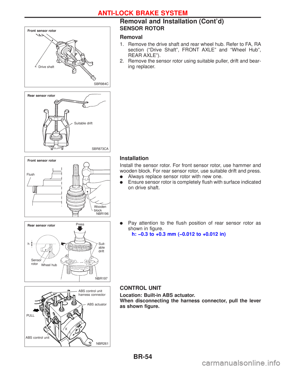
SENSOR ROTOR
Removal
1. Remove the drive shaft and rear wheel hub. Refer to FA, RA
section (ªDrive Shaftº, FRONT AXLEº and ªWheel Hubº,
REAR AXLEº).
2. Remove the sensor rotor using suitable puller, drift and bear-
ing replacer.
Installation
Install the sensor rotor. For front sensor rotor, use hammer and
wooden block. For rear sensor rotor, use suitable drift and press.
lAlways replace sensor rotor with new one.
lEnsure sensor rotor is completely flush with surface indicated
on drive shaft.
lPay attention to the flush position of rear sensor rotor as
shown in figure.
h: þ0.3 to +0.3 mm (þ0.012 to +0.012 in)
CONTROL UNIT
Location: Built-in ABS actuator.
When disconnecting the harness connector, pull the lever
as shown figure.
SBR984C Front sensor rotor
Drive shaft
SBR873CA Rear sensor rotor
Suitable drift
NBR196 Front sensor rotor
Wooden
block Flush
.NBR197 Rear sensor rotorPress
Suit-
able
drift
Sensor
rotor
Wheel hub h
NBR261 ABS control unit
harness connector
ABS control unitABS actuator
X
1
X PULL
ANTI-LOCK BRAKE SYSTEM
Removal and Installation (Cont'd)
BR-54
Page 177 of 2267
ABS ACTUATOR
NBR262 Front master cylinder secondary
To rear wheel cylinder (LH)
To rear wheel cylinder (RH)
Actuator/ground cable
10.8 - 14.7
(1.1 - 1.5,8.0 - 10.8)
: N´m (kg-m, in-lb)
: N´m (kg-m, ft-lb) Actuator bracket7-9
(0.7 - 0.9, 5.1 - 6.5) ABS actuator & electric control
unit
11 - 15 (1.1 - 1.5, 8.0 -10.8)To front wheel cylinder (RH)
To front wheel cylinder (LH)
From master cylinder primary
10 - 14 (1.0 - 1.4, 7.2 - 10.1)
FRONT LockUnlock
ANTI-LOCK BRAKE SYSTEM
Removal and Installation (Cont'd)
BR-55
Page 178 of 2267
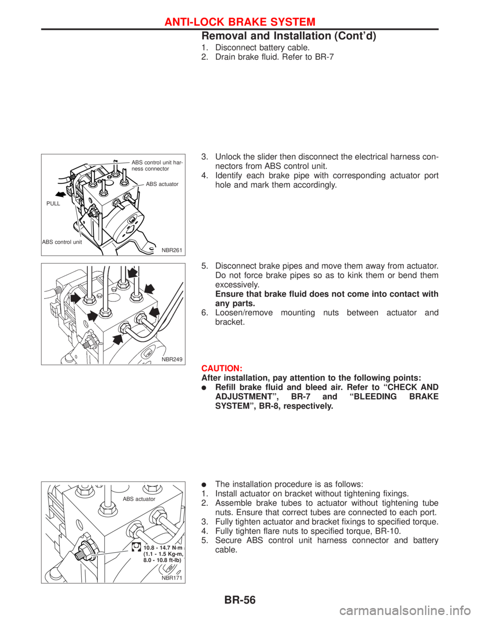
1. Disconnect battery cable.
2. Drain brake fluid. Refer to BR-7
3. Unlock the slider then disconnect the electrical harness con-
nectors from ABS control unit.
4. Identify each brake pipe with corresponding actuator port
hole and mark them accordingly.
5. Disconnect brake pipes and move them away from actuator.
Do not force brake pipes so as to kink them or bend them
excessively.
Ensure that brake fluid does not come into contact with
any parts.
6. Loosen/remove mounting nuts between actuator and
bracket.
CAUTION:
After installation, pay attention to the following points:
lRefill brake fluid and bleed air. Refer to ªCHECK AND
ADJUSTMENTº, BR-7 and ªBLEEDING BRAKE
SYSTEMº, BR-8, respectively.
lThe installation procedure is as follows:
1. Install actuator on bracket without tightening fixings.
2. Assemble brake tubes to actuator without tightening tube
nuts. Ensure that correct tubes are connected to each port.
3. Fully tighten actuator and bracket fixings to specified torque.
4. Fully tighten flare nuts to specified torque, BR-10.
5. Secure ABS control unit harness connector and battery
cable.
NBR261 ABS control unit har-
ness connector
ABS control unitABS actuator
PULL
NBR249
NBR171 ABS actuator
.10.8 - 14.7 N´m
(1.1 - 1.5 Kg-m,
8.0 - 10.8 ft-lb)
ANTI-LOCK BRAKE SYSTEM
Removal and Installation (Cont'd)
BR-56
Page 179 of 2267
How to Perform Trouble Diagnoses for Quick
and Accurate Repair
INTRODUCTION
The ABS system has an electronic control unit to control major
braking functions. The control unit accepts input signals from
sensors and utilises the data to instantly drive the actuators. It is
essential that both input and output signals are correct and
stable. It is also important to check for conventional problems:
such as air leaks in booster lines, lack of brake fluid, or other
problems with the brake system.
It is much more difficult to diagnose a problem that occurs inter-
mittently rather than catastrophically. Most intermittent problems
are caused by poor electric connections or faulty wiring. In this
case, careful checking of suspicious circuits may help prevent
the unnecessary replacement of good parts.
A visual check may not be sufficient to find the cause of the
problems, so a road test should also be performed.
Before undertaking actual checks, take just a few minutes to talk
with a customer who approaches with a ABS complaint. The
customer is a very good source of information on such problems;
especially intermittent ones. Through the talks with the customer,
find out what symptoms are present and under what conditions
they occur.
Start your diagnosis by looking for ªconventionalº problems first.
This is one of the best ways to troubleshoot brake problems on
an ABS controlled vehicle.
SEF233G
SEF234G
TROUBLE DIAGNOSES
BR-57
Page 184 of 2267
Wiring Diagram Ð ABS Ð
MODELS WITH SELF-DIAGNOSIS FUNCTION
YBR208 BATTERYIGNITION SWITCH
ON or START
FUSE
BLOCK
(J/B)Refer to EL-POWER.
: LHD models
: RHD models: CVT models
: M/T models
RELEASEDDEPRESSEDSTOP LAMP
SWITCH
FUSE
BLOCK
(J/B)COMBINATION METER
(ABS WARNING LAMP)
ABS ACTUATOR
AND ELECTRIC
UNIT
(CONTROL UNIT)
TCM
(TRANSMISSION CON-
TROL MODULE)DATA LINK CON-
NECTOR
Refer to las page (Foldout page).
TROUBLE DIAGNOSES
BR-62
Page 189 of 2267
Self-diagnosis (Only models with data link
connector terminal No. 8)
FUNCTION
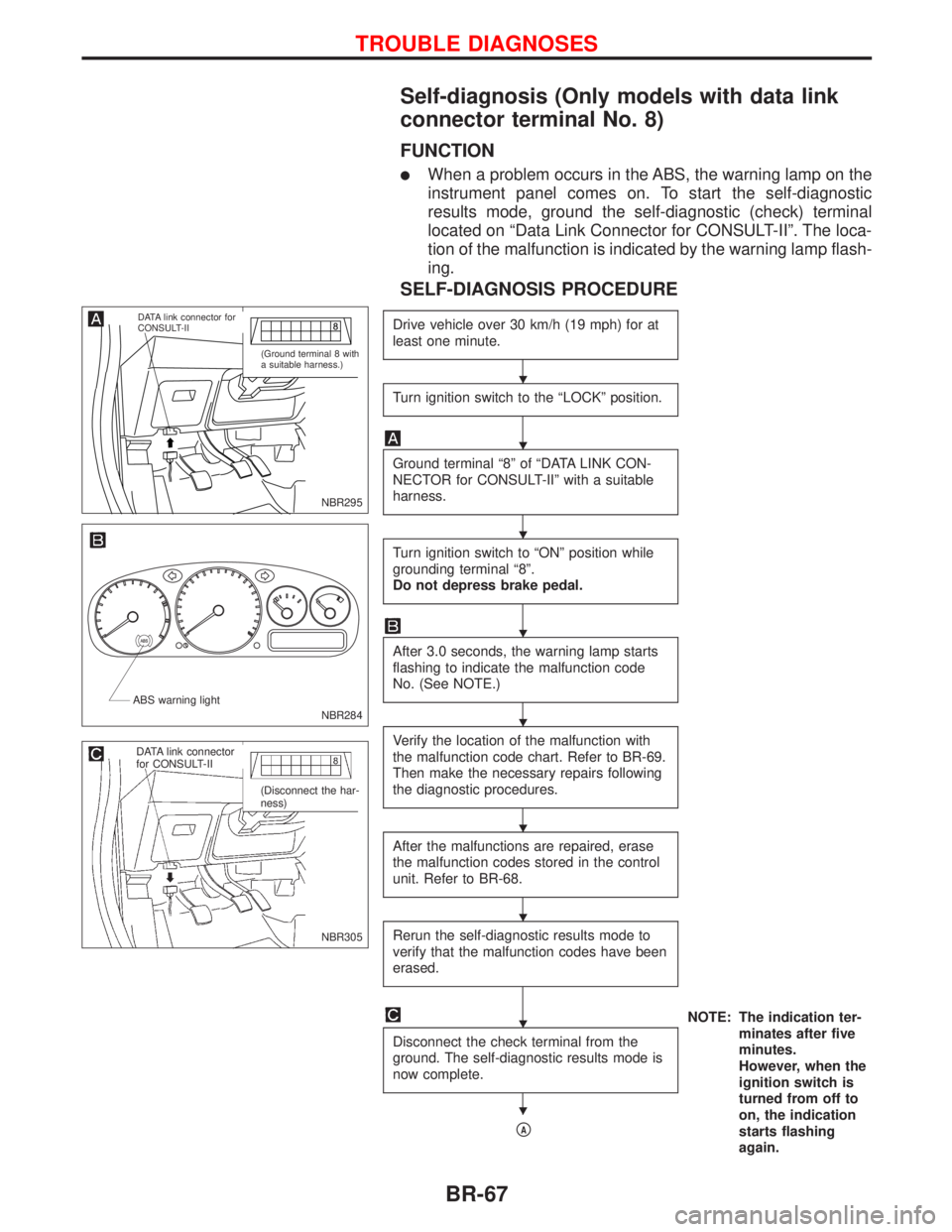
lWhen a problem occurs in the ABS, the warning lamp on the
instrument panel comes on. To start the self-diagnostic
results mode, ground the self-diagnostic (check) terminal
located on ªData Link Connector for CONSULT-IIº. The loca-
tion of the malfunction is indicated by the warning lamp flash-
ing.
SELF-DIAGNOSIS PROCEDURE
Drive vehicle over 30 km/h (19 mph) for at
least one minute.
Turn ignition switch to the ªLOCKº position.
Ground terminal ª8º of ªDATA LINK CON-
NECTOR for CONSULT-IIº with a suitable
harness.
Turn ignition switch to ªONº position while
grounding terminal ª8º.
Do not depress brake pedal.
After 3.0 seconds, the warning lamp starts
flashing to indicate the malfunction code
No. (See NOTE.)
Verify the location of the malfunction with
the malfunction code chart. Refer to BR-69.
Then make the necessary repairs following
the diagnostic procedures.
After the malfunctions are repaired, erase
the malfunction codes stored in the control
unit. Refer to BR-68.
Rerun the self-diagnostic results mode to
verify that the malfunction codes have been
erased.
NOTE: The indication ter-
minates after five
minutes.
However, when the
ignition switch is
turned from off to
on, the indication
starts flashing
again. Disconnect the check terminal from the
ground. The self-diagnostic results mode is
now complete.
pA
NBR295
.DATA link connector for
CONSULT-II
(Ground terminal 8 with
a suitable harness.)
NBR284 ABS warning light
NBR305
.DATA link connector
for CONSULT-II
(Disconnect the har-
ness)
H
H
H
H
H
H
H
H
H
TROUBLE DIAGNOSES
BR-67
Page 191 of 2267
CONSULT-II
CONSULT-II APPLICATION TO ABS
ITEMSELF-DIAGNOSTIC
RESULTSDATA MONITOR ACTIVE TEST
Front right wheel sensor X X Ð
Front left wheel sensor X X Ð
Rear right wheel sensor X X Ð
Rear left wheel sensor X X Ð
Stop lamp switch Ð X Ð
Front right inlet solenoid valve X X X
Front right outlet solenoid valve X X X
Front left inlet solenoid valve X X X
Front left outlet solenoid valve X X X
Rear right inlet solenoid valve X X X
Rear left inlet solenoid valve X X X
Rear right outlet solenoid valve X X X
Rear left outlet solenoid valve X X X
Actuator solenoid valve relay X X Ð
Actuator motor relay
(ABS MOTOR is shown on the Data Monitor screen.)XXX
ABS warning lamp Ð X Ð
Battery voltage X X Ð
Control unit X Ð Ð
X: Applicable
Ð: Not applicable
ECU part number mode
Ignore the ECU part number displayed in the ECU PART NUMBER MODE. Refer to parts catalog to order
the ECU.
Trouble Diagnosis Ð General Description
BR-69
Page 192 of 2267
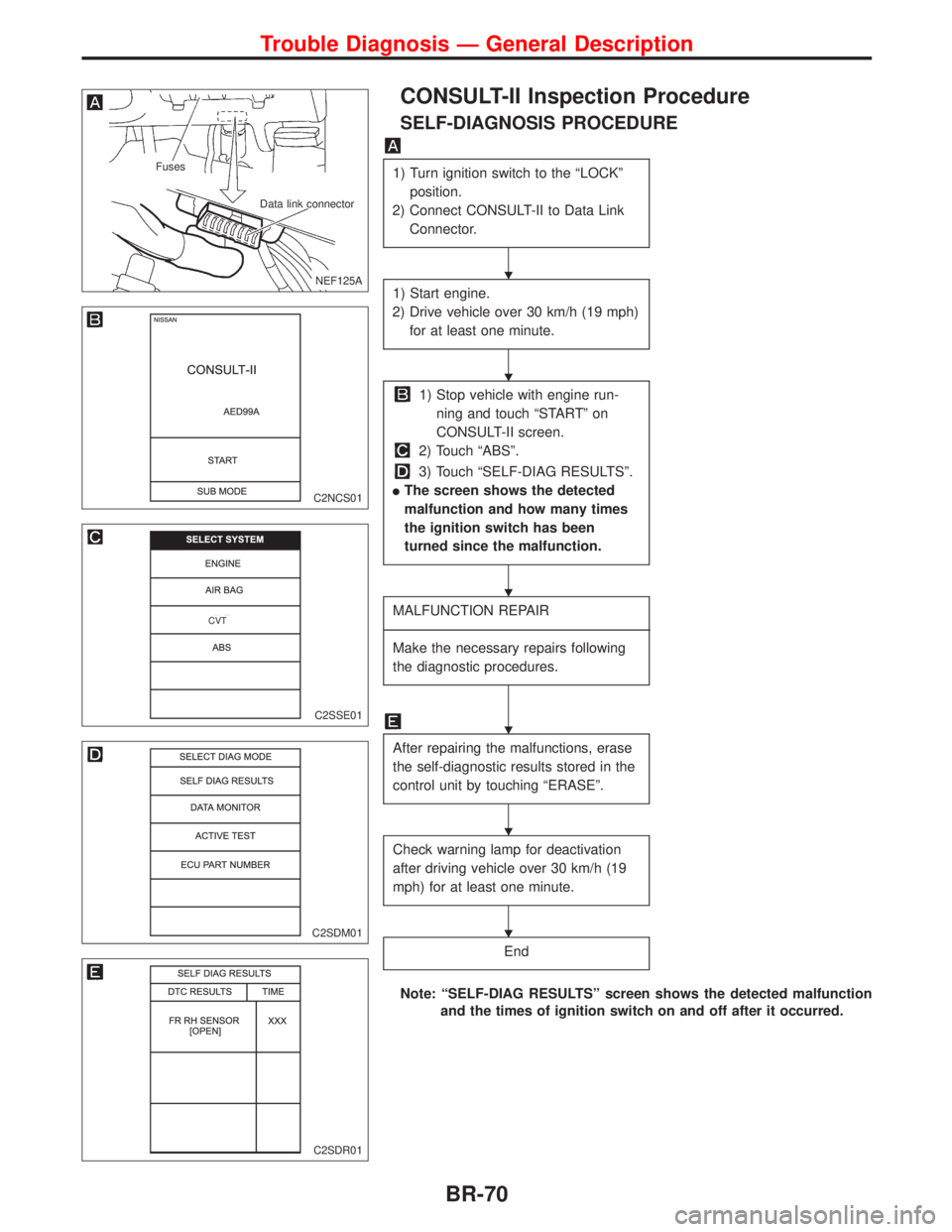
CONSULT-II Inspection Procedure
SELF-DIAGNOSIS PROCEDURE
1) Turn ignition switch to the ªLOCKº
position.
2) Connect CONSULT-II to Data Link
Connector.
1) Start engine.
2) Drive vehicle over 30 km/h (19 mph)
for at least one minute.
1) Stop vehicle with engine run-
ning and touch ªSTARTº on
CONSULT-II screen.
2) Touch ªABSº.
3) Touch ªSELF-DIAG RESULTSº.
lThe screen shows the detected
malfunction and how many times
the ignition switch has been
turned since the malfunction.
MALFUNCTION REPAIR
----------------------------------------------------------------------------------------------------------------------------------------------------------------------------------------------------------------------------------------------------------------------------------------------------------
Make the necessary repairs following
the diagnostic procedures.
After repairing the malfunctions, erase
the self-diagnostic results stored in the
control unit by touching ªERASEº.
Check warning lamp for deactivation
after driving vehicle over 30 km/h (19
mph) for at least one minute.
End
Note: ªSELF-DIAG RESULTSº screen shows the detected malfunction
and the times of ignition switch on and off after it occurred.
.NEF125A
Fuses
Data link connector
C2NCS01
C2SSE01
.CVT
C2SDM01
C2SDR01
H
H
H
H
H
H
Trouble Diagnosis Ð General Description
BR-70