Page 226 of 2267
NBF271 Back door lock adjustment
Back door hinge adjustment
Back door stay installation
Opener
handle
Fuel filler lid control
Back door striker adjustment
*: Bumper assembly mounting clips and screws. Bumper fascia
assemblyRear fender cover
Back door lock control
BODY END
Body Rear End and Opener (Cont'd)
BT-12
Page 229 of 2267

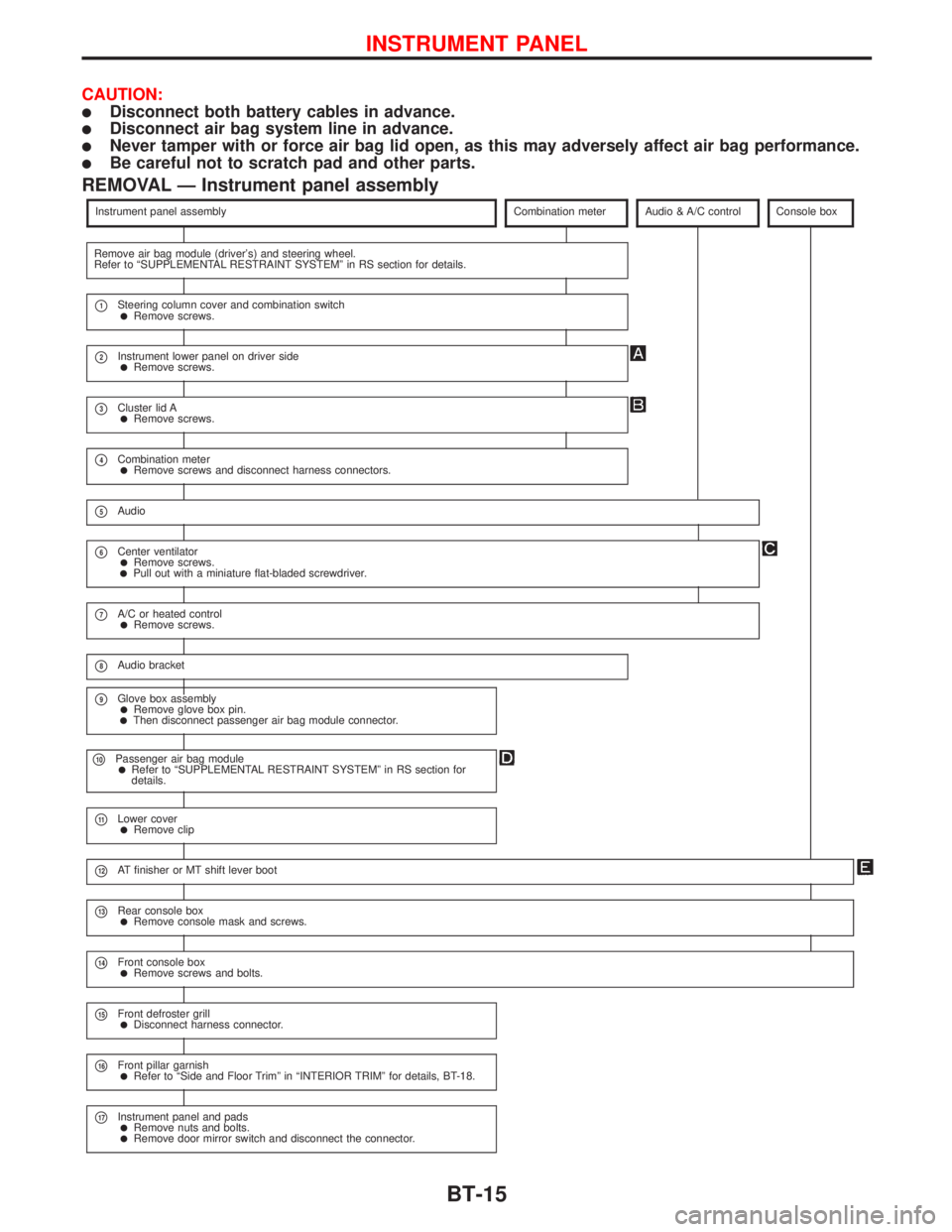
CAUTION:
lDisconnect both battery cables in advance.
lDisconnect air bag system line in advance.
lNever tamper with or force air bag lid open, as this may adversely affect air bag performance.
lBe careful not to scratch pad and other parts.
REMOVAL Ð Instrument panel assembly
Instrument panel assemblyCombination meterAudio & A/C controlConsole box
Remove air bag module (driver's) and steering wheel.
Refer to ªSUPPLEMENTAL RESTRAINT SYSTEMº in RS section for details.
p1Steering column cover and combination switchlRemove screws.
p2Instrument lower panel on driver sidelRemove screws.
p3Cluster lid AlRemove screws.
p4Combination meterlRemove screws and disconnect harness connectors.
p5Audio
p6Center ventilatorlRemove screws.lPull out with a miniature flat-bladed screwdriver.
p7A/C or heated controllRemove screws.
p8Audio bracket
p9Glove box assemblylRemove glove box pin.lThen disconnect passenger air bag module connector.
p10Passenger air bag modulelRefer to ªSUPPLEMENTAL RESTRAINT SYSTEMº in RS section for
details.
p11Lower coverlRemove clip
p12AT finisher or MT shift lever boot
p13Rear console boxlRemove console mask and screws.
p14Front console boxlRemove screws and bolts.
p15Front defroster grilllDisconnect harness connector.
p16Front pillar garnishlRefer to ªSide and Floor Trimº in ªINTERIOR TRIMº for details, BT-18.
p17Instrument panel and padslRemove nuts and bolts.lRemove door mirror switch and disconnect the connector.
INSTRUMENT PANEL
BT-15
Page 279 of 2267

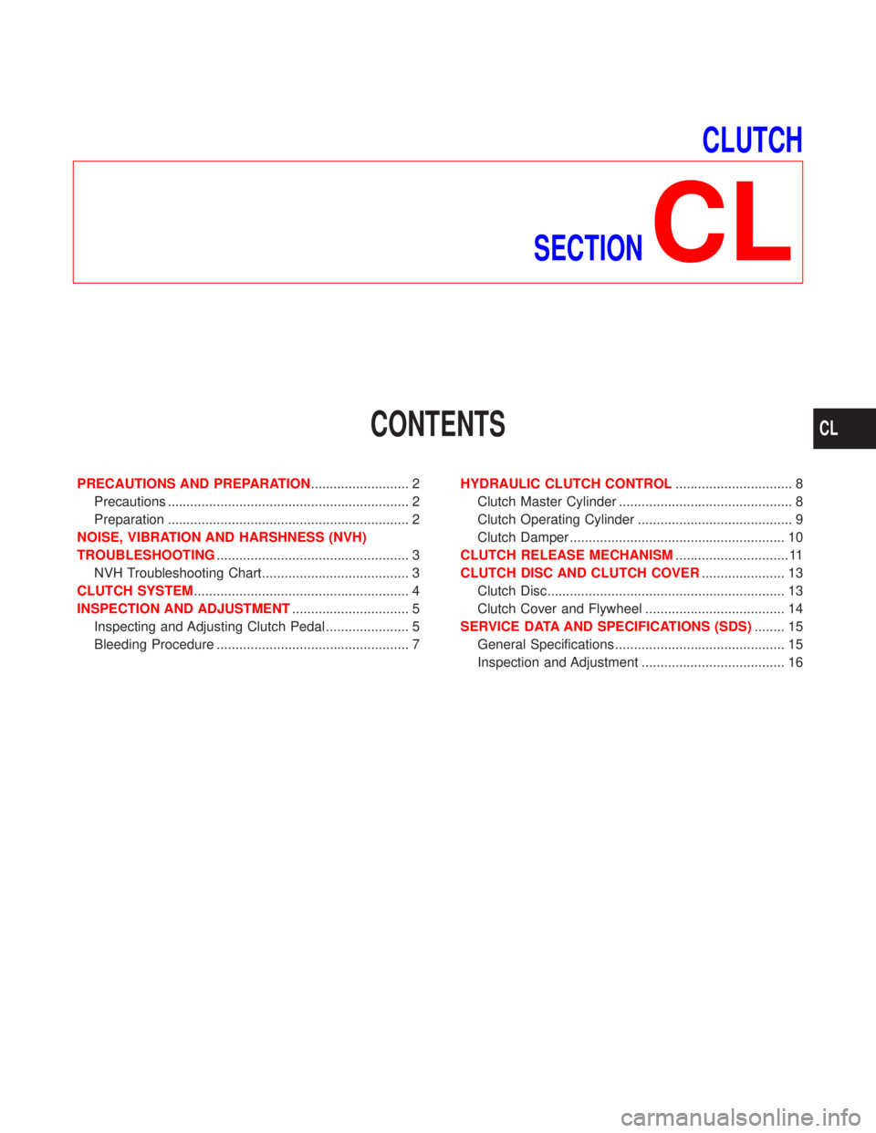
CLUTCH
SECTION
CL
CONTENTS
PRECAUTIONS AND PREPARATION.......................... 2
Precautions ................................................................ 2
Preparation ................................................................ 2
NOISE, VIBRATION AND HARSHNESS (NVH)
TROUBLESHOOTING................................................... 3
NVH Troubleshooting Chart....................................... 3
CLUTCH SYSTEM......................................................... 4
INSPECTION AND ADJUSTMENT............................... 5
Inspecting and Adjusting Clutch Pedal ...................... 5
Bleeding Procedure ................................................... 7HYDRAULIC CLUTCH CONTROL............................... 8
Clutch Master Cylinder .............................................. 8
Clutch Operating Cylinder ......................................... 9
Clutch Damper ......................................................... 10
CLUTCH RELEASE MECHANISM.............................. 11
CLUTCH DISC AND CLUTCH COVER...................... 13
Clutch Disc............................................................... 13
Clutch Cover and Flywheel ..................................... 14
SERVICE DATA AND SPECIFICATIONS (SDS)........ 15
General Specifications ............................................. 15
Inspection and Adjustment ...................................... 16
CL
Page 286 of 2267
Clutch Master Cylinder
DISASSEMBLY AND ASSEMBLY
lPush piston into cylinder body with screwdriver when remov-
ing and installing valve stopper.
lCheck direction of piston cups.
INSPECTION
lCheck cylinder and piston contact surfaces for uneven wear,
rust or damage. Replace if necessary.
lCheck piston and piston cup for wear or damage. Replace if
necessary.
lCheck return spring for wear or damage. Replace if neces-
sary.
lCheck reservoir for deformation or damage. Replace if
necessary.
lCheck dust cover for cracks, deformation or damage.
Replace if necessary.
YCL008
HYDRAULIC CLUTCH CONTROL
CL-8
Page 287 of 2267
Clutch Operating Cylinder
INSPECTION
lCheck contact surfaces of cylinder for wear, rust or damage.
Replace if necessary.
lCheck piston and piston cup for wear or damage. Replace if
necessary
lCheck piston spring for wear or damage. Replace if neces-
sary.
lCheck dust cover for cracks, deformation or damage.
Replace if necessary.
NCL008
18 - 25 (1.9 - 2.5, 14 - 18) Hydraulic pipe
Air bleeder valve
7 - 9 (0.8 - 0.9, 62 - 79)
30 - 38 (3.1 - 3.8, 23 - 28)
Operating cylinder
pR
Spacer
Dust cover
Push rod
Spring
Piston assembly
Piston cup
pR
pR: Apply rubber
grease
: N´m (kg-m, ft-lb)
: N´m (kg-m, in-lb)
SEC. 306
HYDRAULIC CLUTCH CONTROL
CL-9
Page 288 of 2267
Clutch Damper
DISASSEMBLY AND ASSEMBLY
1. Remove damper assembly mounting bolts.
2. Remove gasket, damper rubber, plate, piston assembly, and
piston spring from cylinder body.
3. Clean gasket contact surface on cylinder body and damper
bracket with scrapers.
CAUTION:
Be careful not to scratch the contact surface.
INSPECTION
lCheck cylinder and piston contact surfaces for uneven wear,
rust or damage. Replace if necessary.
lCheck damper rubber and piston cup for cracks, deformation
or damage. Replace if necessary.
NCL009 Bleeder Screw
6-10
(0.7 - 1.0,
54 - 88)Cylinder body
Gasket
Damper cover
(LHD model)
2.9 - 5.9
(0.29 - 0.60,
26 - 52)
5.1 - 6.5
(0.52 - 0.66, 46 - 57)Damper rubber
pRContact surface to piston assemblyPlate Piston assembly Piston cup
pR
pRRubbing sur-
face to piston assembly
Spring
: Do not re-use
: N´m (kg-m, in-lb)
pR: Apply rubber grease
SEC. 306
HYDRAULIC CLUTCH CONTROL
CL-10
Page 293 of 2267
General Specifications
CLUTCH CONTROL SYSTEM
Type of clutch control Hydraulic
CLUTCH DAMPER
Inner diameter mm (in) 19.05 (3/4)
CLUTCH MASTER CYLINDER
Inner diameter mm (in) 15.87 (5/8)
CLUTCH OPERATING CYLINDER
Inner diameter mm (in) 17.46 (11/16)
CLUTCH DISC
Unit: mm (in)
Engine QG16DE, QG18DE, SR20DE CD20T
Model 215 225
Facing size
(Outer dia. x inner dia. x thickness)216 x 153 x 3.5
(8.50 x 6.02 x 0.138)225 x 150 x 3.5
(8.86 x 5.91 x 0.138)
Thickness of disc assembly with load7.3 - 7.9 (0.287 - 0.311)
with 4,900 N (499.8 kg, 1,101.5 lb)7.6 - 8.0 (0.299 - 0.315)
with 3,923 N (400 kg, 882 lb)
CLUTCH COVER
Engine QG16DE, QG18DE, SR20DE CD20T
Model L215K L225K
Full-load N (kg, lb) 4,413 (450, 992)
SERVICE DATA AND SPECIFICATIONS (SDS)
CL-15
Page 295 of 2267

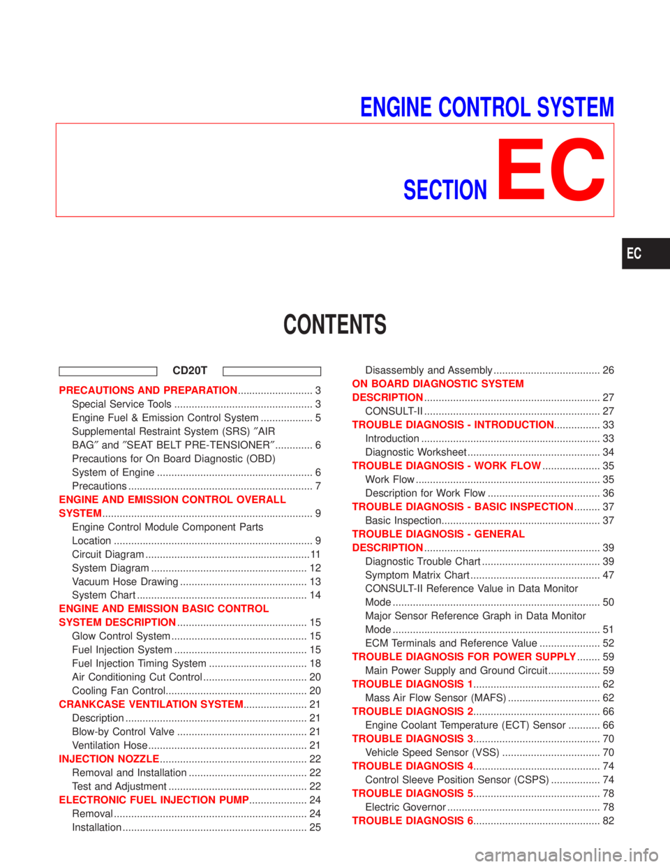
ENGINE CONTROL SYSTEM
SECTION
EC
CONTENTS
CD20T
PRECAUTIONS AND PREPARATION.......................... 3
Special Service Tools ................................................ 3
Engine Fuel & Emission Control System .................. 5
Supplemental Restraint System (SRS)²AIR
BAG²and²SEAT BELT PRE-TENSIONER²............. 6
Precautions for On Board Diagnostic (OBD)
System of Engine ...................................................... 6
Precautions ................................................................ 7
ENGINE AND EMISSION CONTROL OVERALL
SYSTEM......................................................................... 9
Engine Control Module Component Parts
Location ..................................................................... 9
Circuit Diagram ......................................................... 11
System Diagram ...................................................... 12
Vacuum Hose Drawing ............................................ 13
System Chart ........................................................... 14
ENGINE AND EMISSION BASIC CONTROL
SYSTEM DESCRIPTION............................................. 15
Glow Control System ............................................... 15
Fuel Injection System .............................................. 15
Fuel Injection Timing System .................................. 18
Air Conditioning Cut Control .................................... 20
Cooling Fan Control................................................. 20
CRANKCASE VENTILATION SYSTEM...................... 21
Description ............................................................... 21
Blow-by Control Valve ............................................. 21
Ventilation Hose ....................................................... 21
INJECTION NOZZLE................................................... 22
Removal and Installation ......................................... 22
Test and Adjustment ................................................ 22
ELECTRONIC FUEL INJECTION PUMP.................... 24
Removal ................................................................... 24
Installation ................................................................ 25Disassembly and Assembly ..................................... 26
ON BOARD DIAGNOSTIC SYSTEM
DESCRIPTION............................................................. 27
CONSULT-II ............................................................. 27
TROUBLE DIAGNOSIS - INTRODUCTION................ 33
Introduction .............................................................. 33
Diagnostic Worksheet .............................................. 34
TROUBLE DIAGNOSIS - WORK FLOW.................... 35
Work Flow ................................................................ 35
Description for Work Flow ....................................... 36
TROUBLE DIAGNOSIS - BASIC INSPECTION......... 37
Basic Inspection....................................................... 37
TROUBLE DIAGNOSIS - GENERAL
DESCRIPTION............................................................. 39
Diagnostic Trouble Chart ......................................... 39
Symptom Matrix Chart ............................................. 47
CONSULT-II Reference Value in Data Monitor
Mode ........................................................................ 50
Major Sensor Reference Graph in Data Monitor
Mode ........................................................................ 51
ECM Terminals and Reference Value ..................... 52
TROUBLE DIAGNOSIS FOR POWER SUPPLY........ 59
Main Power Supply and Ground Circuit .................. 59
TROUBLE DIAGNOSIS 1............................................ 62
Mass Air Flow Sensor (MAFS) ................................ 62
TROUBLE DIAGNOSIS 2............................................ 66
Engine Coolant Temperature (ECT) Sensor ........... 66
TROUBLE DIAGNOSIS 3............................................ 70
Vehicle Speed Sensor (VSS) .................................. 70
TROUBLE DIAGNOSIS 4............................................ 74
Control Sleeve Position Sensor (CSPS) ................. 74
TROUBLE DIAGNOSIS 5............................................ 78
Electric Governor ..................................................... 78
TROUBLE DIAGNOSIS 6............................................ 82
EC