Page 296 of 2267

Injection Timing Control Valve ................................. 82
TROUBLE DIAGNOSIS 7............................................ 86
Engine Control Module (ECM) ................................ 86
TROUBLE DIAGNOSIS 8............................................ 87
Cooling Fan (Overheat) ........................................... 87
TROUBLE DIAGNOSIS 9............................................ 97
Needle Lift Sensor (NLS) ........................................ 97
TROUBLE DIAGNOSIS 10........................................ 100
Fuel Cut Solenoid Valve ........................................ 100
TROUBLE DIAGNOSIS 11........................................ 104
Fuel Temperature Sensor (FTS)............................ 104
TROUBLE DIAGNOSIS 12........................................ 108
Accelerator Position Sensor & Switch ................... 108
TROUBLE DIAGNOSIS 13......................................... 114
Crankshaft Position Sensor (TDC) ......................... 114
TROUBLE DIAGNOSES 14....................................... 118
Glow Control System .............................................. 118TROUBLE DIAGNOSES 15...................................... 126
Air Conditioner Cut Control ................................... 126
TROUBLE DIAGNOSES 16...................................... 129
EGRC-Solenoid Valve ........................................... 129
TROUBLE DIAGNOSES 17...................................... 136
Brake Switch .......................................................... 136
TROUBLE DIAGNOSES 18...................................... 140
ECM Relay............................................................. 140
TROUBLE DIAGNOSES 19...................................... 141
MI & Data Link Connectors ................................... 141
TROUBLE DIAGNOSES 20...................................... 145
Start Signal ............................................................ 145
SERVICE DATA AND SPECIFICATIONS (SDS)...... 147
General Specifications ........................................... 147
Injection Nozzle ..................................................... 147
Inspection and Adjustment .................................... 147
When you read wiring diagrams:
lRead GI section, ªHOW TO READ WIRING DIAGRAMSº.
lSee EL section, ªPOWER SUPPLY ROUTINGº for power distribution circuit.
lSee EL section for NATS information and wiring diagram.
When you perform trouble diagnoses, read GI section, ªHOW TO FOLLOW FLOW CHART
IN TROUBLE DIAGNOSESº and ªHOW TO PERFORM EFFICIENT DIAGNOSIS FOR AN
ELECTRICAL INCIDENTº.
For clarification of system component abbreviations and terminology read GI section
ªSAE J1930 TERMINOLOGY LISTº.
EC-2
Page 299 of 2267

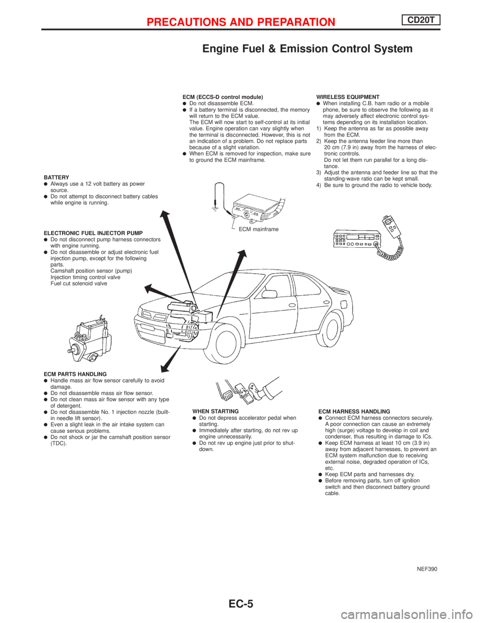
Engine Fuel & Emission Control System
NEF390 ECM (ECCS-D control module)
lDo not disassemble ECM.lIf a battery terminal is disconnected, the memory
will return to the ECM value.
The ECM will now start to self-control at its initial
value. Engine operation can vary slightly when
the terminal is disconnected. However, this is not
an indication of a problem. Do not replace parts
because of a slight variation.
lWhen ECM is removed for inspection, make sure
to ground the ECM mainframe.WIRELESS EQUIPMENT
lWhen installing C.B. ham radio or a mobile
phone, be sure to observe the following as it
may adversely affect electronic control sys-
tems depending on its installation location.
1) Keep the antenna as far as possible away
from the ECM.
2) Keep the antenna feeder line more than
20 cm (7.9 in) away from the harness of elec-
tronic controls.
Do not let them run parallel for a long dis-
tance.
3) Adjust the antenna and feeder line so that the
standing-wave ratio can be kept small.
4) Be sure to ground the radio to vehicle body.
ECM HARNESS HANDLING
lConnect ECM harness connectors securely.
A poor connection can cause an extremely
high (surge) voltage to develop in coil and
condenser, thus resulting in damage to ICs.
lKeep ECM harness at least 10 cm (3.9 in)
away from adjacent harnesses, to prevent an
ECM system malfunction due to receiving
external noise, degraded operation of ICs,
etc.
lKeep ECM parts and harnesses dry.lBefore removing parts, turn off ignition
switch and then disconnect battery ground
cable. WHEN STARTING
lDo not depress accelerator pedal when
starting.
lImmediately after starting, do not rev up
engine unnecessarily.
lDo not rev up engine just prior to shut-
down. ECM PARTS HANDLING
lHandle mass air flow sensor carefully to avoid
damage.
lDo not disassemble mass air flow sensor.lDo not clean mass air flow sensor with any type
of detergent.
lDo not disassemble No. 1 injection nozzle (built-
in needle lift sensor).
lEven a slight leak in the air intake system can
cause serious problems.
lDo not shock or jar the camshaft position sensor
(TDC). ELECTRONIC FUEL INJECTOR PUMP
lDo not disconnect pump harness connectors
with engine running.
lDo not disassemble or adjust electronic fuel
injection pump, except for the following
parts.
Camshaft position sensor (pump)
Injection timing control valve
Fuel cut solenoid valve BATTERY
lAlways use a 12 volt battery as power
source.
lDo not attempt to disconnect battery cables
while engine is running.
ECM mainframe
PRECAUTIONS AND PREPARATIONCD20T
EC-5
Page 303 of 2267
Engine Control Module Component Parts
Location
YEC133A
ENGINE AND EMISSION CONTROL OVERALL SYSTEMCD20T
EC-9
Page 304 of 2267
YEC134A
ENGINE AND EMISSION CONTROL OVERALL SYSTEMCD20T
Engine Control Module Component Parts
Location (Cont'd)
EC-10
Page 305 of 2267
Circuit Diagram
YEC099A
ENGINE AND EMISSION CONTROL OVERALL SYSTEMCD20T
EC-11
Page 306 of 2267
System Diagram
YEC125A
ENGINE AND EMISSION CONTROL OVERALL SYSTEMCD20T
EC-12
Page 307 of 2267
Vacuum Hose Drawing
p1EGRC-solenoid valves A and B to EGR valve
p2EGRC-solenoid valves A and B to air duct
p3EGRC-solenoid valve A to vacuum pump
Refer to ªSystem Diagramº on previous page for vacuum control system.
YEC131A
ENGINE AND EMISSION CONTROL OVERALL SYSTEMCD20T
EC-13
Page 308 of 2267
System Chart
Crankshaft position sensor
(TDC)E
ECM
Control sleeve position sensorE
Fuel temperature sensorE
Mass air flow sensorE
Engine coolant temperature
sensorE
Needle lift sensorE
Accelerator position sensorE
Accelerator position switchE
Air conditioner switchE
Ignition switch (ON & ST POS.)E
Battery voltageE
Vehicle speed sensor or ABS
actuator and electric unit (con-
trol unit)E
Brake switchE
Atmospheric pressure sensorE
EFuel injection controlEElectric governor
EFuel injection timing controlEInjection timing control
valve
EFuel cut controlEFuel cut solenoid valve
EGlow control systemEGlow relay & glow lamp
EOn board diagnostic systemEMalfunction indicator
(On the instrument panel)
EEGR valve controlEEGRC-solenoid valve A & B
ECooling fan controlECooling fan relays
EAir conditioning cut controlEAir conditioner relay
ECooling fan motor controlECooling fan relay
ENGINE AND EMISSION CONTROL OVERALL SYSTEMCD20T
EC-14