Page 210 of 2267
lApplying brake gradually when shifting or operating clutch.
lLow friction (slippery) road.
lHigh speed concerning.
lDriving over bumps and pot holes.
lEngine speed is over 5,000 rpm with vehicle stopped.
Diagnostic Procedure 11 (ABS Warning lamp
does not come on when ignition switch is
turned ON)
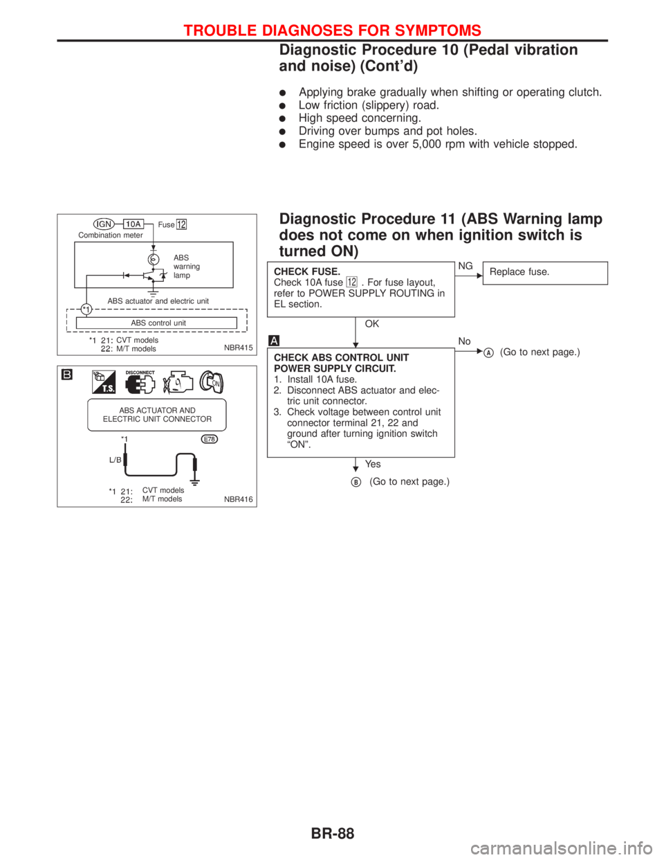
CHECK FUSE.
Check 10A fuse12. For fuse layout,
refer to POWER SUPPLY ROUTING in
EL section.
OK
ENG
Replace fuse.
CHECK ABS CONTROL UNIT
POWER SUPPLY CIRCUIT.
1. Install 10A fuse.
2. Disconnect ABS actuator and elec-
tric unit connector.
3. Check voltage between control unit
connector terminal 21, 22 and
ground after turning ignition switch
ªONº.
Ye s
ENo
pA(Go to next page.)
pB(Go to next page.)
NBR415
.Fuse
Combination meter
ABS
warning
lamp
CVT models
M/T modelsABS control unit ABS actuator and electric unit
NBR416
ABS ACTUATOR AND
ELECTRIC UNIT CONNECTOR
CVT models
M/T models
H
H
TROUBLE DIAGNOSES FOR SYMPTOMS
Diagnostic Procedure 10 (Pedal vibration
and noise) (Cont'd)
BR-88
Page 212 of 2267
Diagnostic Procedure 12 (Warning lamp
stays on when ignition switch is turned ON)
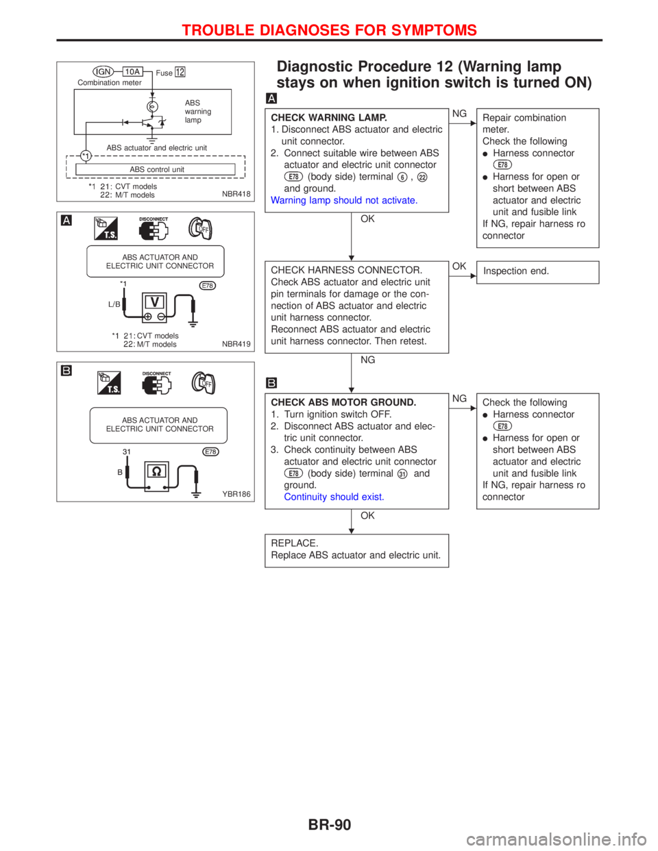
CHECK WARNING LAMP.
1. Disconnect ABS actuator and electric
unit connector.
2. Connect suitable wire between ABS
actuator and electric unit connector
E78(body side) terminalp6,p22
and ground.
Warning lamp should not activate.
OK
ENG
Repair combination
meter.
Check the following
lHarness connector
E78
lHarness for open or
short between ABS
actuator and electric
unit and fusible link
If NG, repair harness ro
connector
CHECK HARNESS CONNECTOR.
Check ABS actuator and electric unit
pin terminals for damage or the con-
nection of ABS actuator and electric
unit harness connector.
Reconnect ABS actuator and electric
unit harness connector. Then retest.
NG
EOK
Inspection end.
CHECK ABS MOTOR GROUND.
1. Turn ignition switch OFF.
2. Disconnect ABS actuator and elec-
tric unit connector.
3. Check continuity between ABS
actuator and electric unit connector
E78(body side) terminalp31and
ground.
Continuity should exist.
OK
ENG
Check the following
lHarness connector
E78
lHarness for open or
short between ABS
actuator and electric
unit and fusible link
If NG, repair harness ro
connector
REPLACE.
Replace ABS actuator and electric unit.
NBR418
.Fuse
Combination meter
ABS
warning
lamp
CVT models
M/T modelsABS control unit ABS actuator and electric unit
NBR419
ABS ACTUATOR AND
ELECTRIC UNIT CONNECTOR
CVT models
M/T models
YBR186
ABS ACTUATOR AND
ELECTRIC UNIT CONNECTOR
H
H
H
TROUBLE DIAGNOSES FOR SYMPTOMS
BR-90
Page 213 of 2267
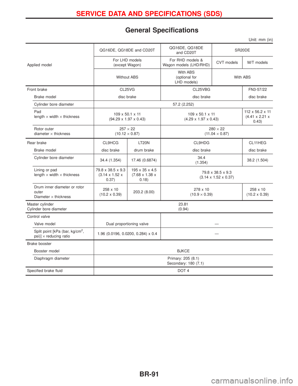
General Specifications
Unit: mm (in)
Applied modelQG16DE, QG18DE and CD20TQG16DE, QG18DE
and CD20TSR20DE
For LHD models
(except Wagon)For RHD models &
Wagon models (LHD/RHD)CVT models M/T models
Without ABSWith ABS
(optional for
LHD models)With ABS
Front brake CL25VG CL25VBG FN3-57/22
Brake model disc brake disc brake disc brake
Cylinder bore diameter 57.2 (2.252)
Pad
length´width´thickness109 x 50.1 x 11
(94.29 x 1.97 x 0.43)109 x 50.1 x 11
(4.29 x 1.97 x 0.43)112x56.2x11
(4.41 x 2.21 x
0.43)
Rotor outer
diameter´thickness257´22
(10.12´0.87)280´22
(11.04´0.87)
Rear brake CL9HCG LT20N CL9HDG CL11HEG
Brake model disc brake drum brake disc brake disc brake
Cylinder bore diameter
34.4 (1.354) 17.46 (0.6874)34.4
(1.354)38.2 (1.504)
Lining or pad
length´width´thickness79.8 x 38.5 x 9.3
(3.14 x 1.52 x
0.37)195x35x4.5
(7.68 x 1.38 x
0.18)79.8 x 38.5 x 9.3
(3.14 x 1.52 x 0.37)
Drum inner diameter or rotor
outer
Diameter´thickness258x10
(10.2 x 0.39)203.2 (8.00)278x10
(10.9´0.39)258x10
(10.2 x 0.39)
Master cylinder
Cylinder bore diameter23.81
(0.94)
Control valve
Valve model Dual proportioning valve Ð
Split point [kPa (bar, kg/cm
2,
psi)]´reducing ratio1.96 (0.0196, 0.0200, 0.284) x 0.4 Ð
Brake booster
Booster model BJKCE
Diaphragm diameter Primary: 205 (8.1)
Secondary: 180 (7.1)
Specified brake fluid DOT 4
SERVICE DATA AND SPECIFICATIONS (SDS)
BR-91
Page 214 of 2267
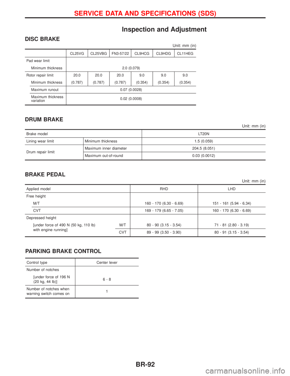
Inspection and Adjustment
DISC BRAKE
Unit: mm (in)
CL25VG CL25VBG FN3-57/22 CL9HCG CL9HDG CL11HEG
Pad wear limit
Minimum thickness 2.0 (0.079)
Rotor repair limit 20.0 20.0 20.0 9.0 9.0 9.0
Minimum thickness (0.787) (0.787) (0.787) (0.354) (0.354) (0.354)
Maximum runout 0.07 (0.0028)
Maximum thickness
variation0.02 (0.0008)
DRUM BRAKE
Unit: mm (in)
Brake modelLT20N
Lining wear limit Minimum thickness 1.5 (0.059)
Drum repair limitMaximum inner diameter 204.5 (8.051)
Maximum out-of-round 0.03 (0.0012)
BRAKE PEDAL
Unit: mm (in)
Applied model RHD LHD
Free height
M/T 160 - 170 (6.30 - 6.69) 151 - 161 (5.94 - 6.34)
CVT 169 - 179 (6.65 - 7.05) 160 - 170 (6.30 - 6.69)
Depressed height
[under force of 490 N (50 kg, 110 lb)
with engine running]M/T 80 - 90 (3.15 - 3.54) 71 - 81 (2.80 - 3.19)
CVT 89 - 99 (3.50 - 3.90) 80 - 91 (3.15 - 3.54)
PARKING BRAKE CONTROL
Control type Center lever
Number of notches
[under force of 196 N
(20 kg, 44 lb)]6-8
Number of notches when
warning switch comes on1
SERVICE DATA AND SPECIFICATIONS (SDS)
BR-92
Page 219 of 2267
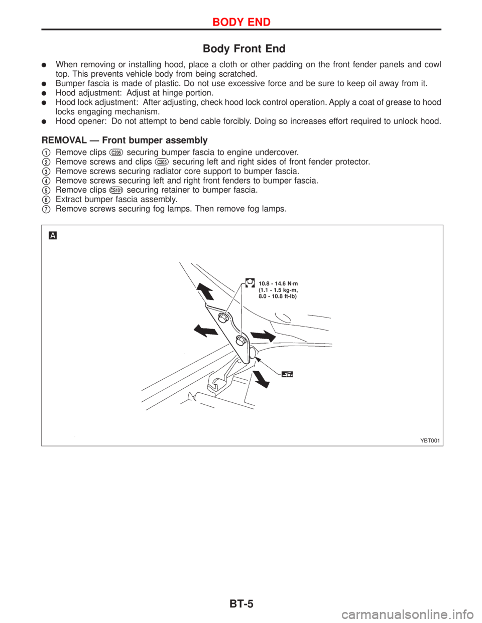
Body Front End
lWhen removing or installing hood, place a cloth or other padding on the front fender panels and cowl
top. This prevents vehicle body from being scratched.
lBumper fascia is made of plastic. Do not use excessive force and be sure to keep oil away from it.
lHood adjustment: Adjust at hinge portion.
lHood lock adjustment: After adjusting, check hood lock control operation. Apply a coat of grease to hood
locks engaging mechanism.
lHood opener: Do not attempt to bend cable forcibly. Doing so increases effort required to unlock hood.
REMOVAL Ð Front bumper assembly
p1Remove clipsC205securing bumper fascia to engine undercover.
p2Remove screws and clipsC205securing left and right sides of front fender protector.
p3Remove screws securing radiator core support to bumper fascia.
p4Remove screws securing left and right front fenders to bumper fascia.
p5Remove clipsCS101securing retainer to bumper fascia.
p6Extract bumper fascia assembly.
p7Remove screws securing fog lamps. Then remove fog lamps.
YBT001
10.8 - 14.6 N´m
(1.1 - 1.5 kg-m,
8.0 - 10.8 ft-lb)
BODY END
BT-5
Page 221 of 2267
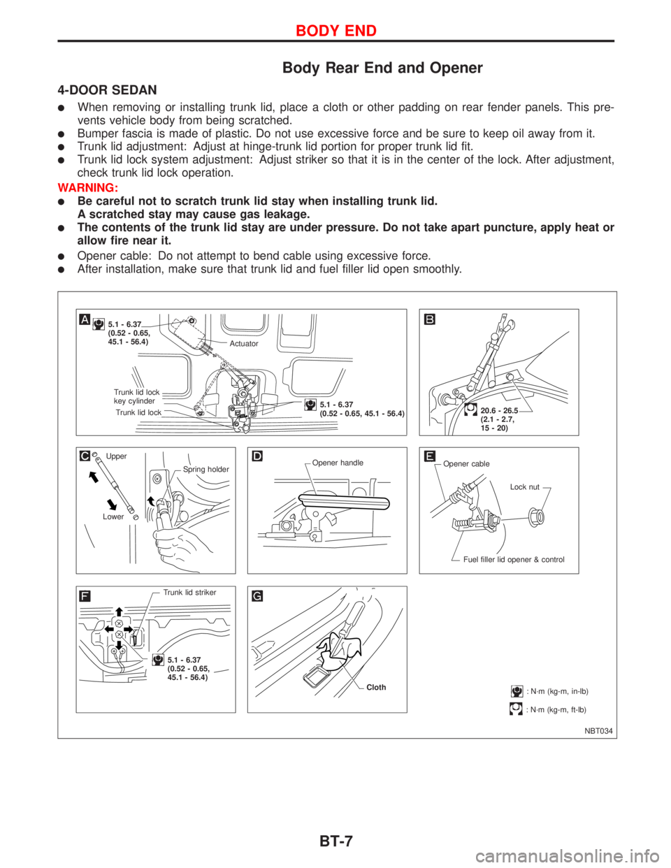
Body Rear End and Opener
4-DOOR SEDAN
lWhen removing or installing trunk lid, place a cloth or other padding on rear fender panels. This pre-
vents vehicle body from being scratched.
lBumper fascia is made of plastic. Do not use excessive force and be sure to keep oil away from it.
lTrunk lid adjustment: Adjust at hinge-trunk lid portion for proper trunk lid fit.
lTrunk lid lock system adjustment: Adjust striker so that it is in the center of the lock. After adjustment,
check trunk lid lock operation.
WARNING:
lBe careful not to scratch trunk lid stay when installing trunk lid.
A scratched stay may cause gas leakage.
lThe contents of the trunk lid stay are under pressure. Do not take apart puncture, apply heat or
allow fire near it.
lOpener cable: Do not attempt to bend cable using excessive force.
lAfter installation, make sure that trunk lid and fuel filler lid open smoothly.
NBT034
5.1 - 6.37
(0.52 - 0.65,
45.1 - 56.4)
Upper
Spring holder
LowerOpener handle
Opener cable
Lock nut
Fuel filler lid opener & control
Trunk lid striker
.5.1 - 6.37
(0.52 - 0.65,
45.1 - 56.4)
: N´m (kg-m, ft-lb)
20.6 - 26.5
(2.1 - 2.7,
15 - 20)
: N´m (kg-m, in-lb) Cloth
Actuator
.Trunk lid lock
key cylinder
.Trunk lid lock
.5.1 - 6.37
(0.52 - 0.65, 45.1 - 56.4)
BODY END
BT-7
Page 223 of 2267
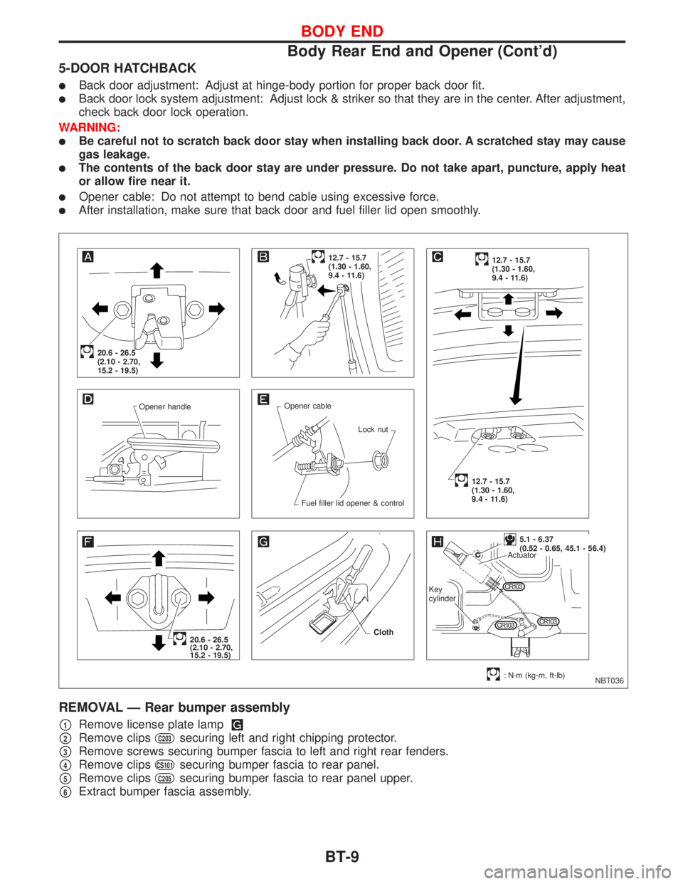
5-DOOR HATCHBACK
lBack door adjustment: Adjust at hinge-body portion for proper back door fit.
lBack door lock system adjustment: Adjust lock & striker so that they are in the center. After adjustment,
check back door lock operation.
WARNING:
lBe careful not to scratch back door stay when installing back door. A scratched stay may cause
gas leakage.
lThe contents of the back door stay are under pressure. Do not take apart, puncture, apply heat
or allow fire near it.
lOpener cable: Do not attempt to bend cable using excessive force.
lAfter installation, make sure that back door and fuel filler lid open smoothly.
REMOVAL Ð Rear bumper assembly
p1Remove license plate lamp
p2Remove clipsC203securing left and right chipping protector.
p3Remove screws securing bumper fascia to left and right rear fenders.
p4Remove clipsCS101securing bumper fascia to rear panel.
p5Remove clipsC205securing bumper fascia to rear panel upper.
p6Extract bumper fascia assembly.
NBT036 Opener handleOpener cable
Lock nut
Fuel filler lid opener & control
20.6 - 26.5
(2.10 - 2.70,
15.2 - 19.5)
12.7 - 15.7
(1.30 - 1.60,
9.4 - 11.6)12.7 - 15.7
(1.30 - 1.60,
9.4 - 11.6)
12.7 - 15.7
(1.30 - 1.60,
9.4 - 11.6)
20.6 - 26.5
(2.10 - 2.70,
15.2 - 19.5)
: N´m (kg-m, ft-lb) Cloth
.5.1 - 6.37
(0.52 - 0.65, 45.1 - 56.4)
Actuator
Key
cylinder
BODY END
Body Rear End and Opener (Cont'd)
BT-9
Page 225 of 2267
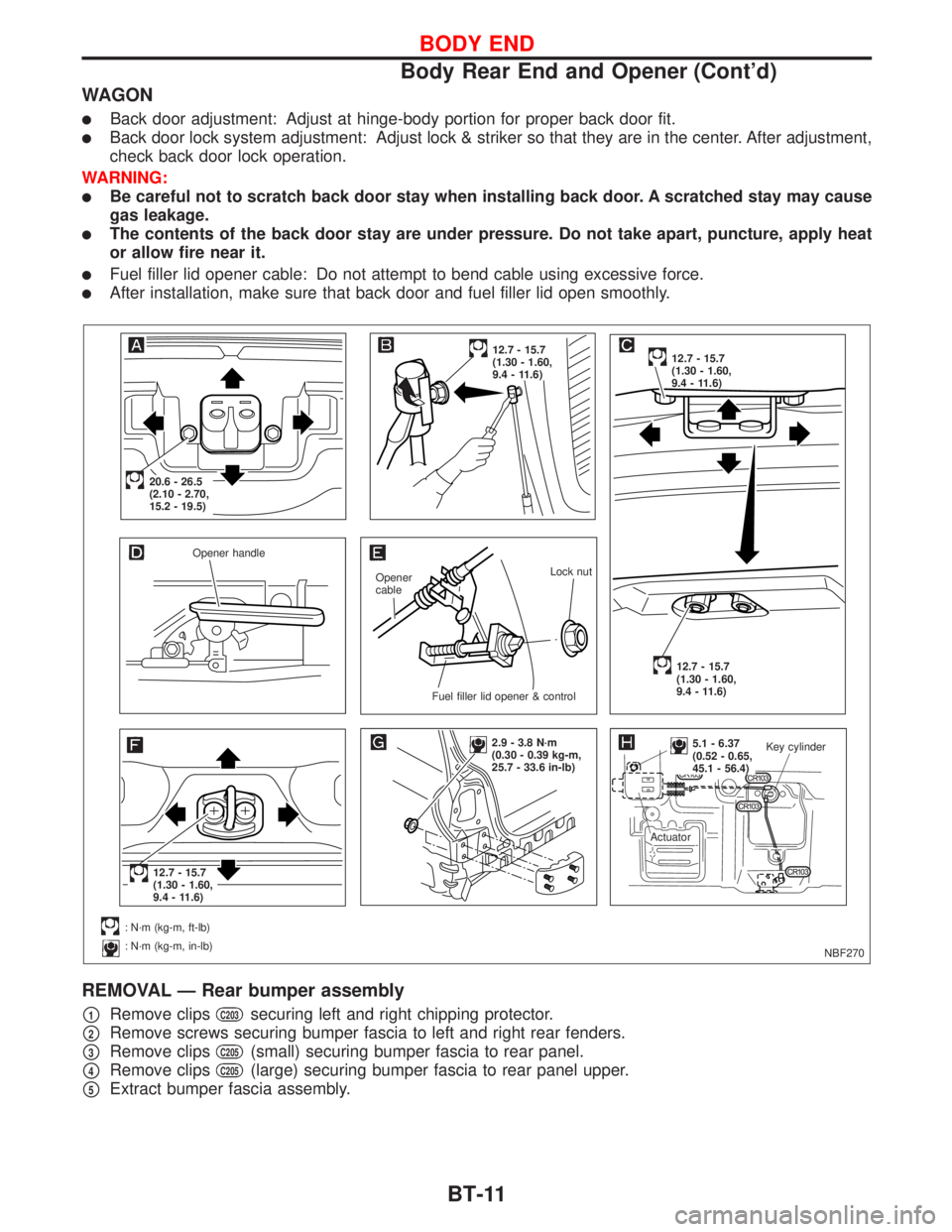
WAGON
lBack door adjustment: Adjust at hinge-body portion for proper back door fit.
lBack door lock system adjustment: Adjust lock & striker so that they are in the center. After adjustment,
check back door lock operation.
WARNING:
lBe careful not to scratch back door stay when installing back door. A scratched stay may cause
gas leakage.
lThe contents of the back door stay are under pressure. Do not take apart, puncture, apply heat
or allow fire near it.
lFuel filler lid opener cable: Do not attempt to bend cable using excessive force.
lAfter installation, make sure that back door and fuel filler lid open smoothly.
REMOVAL Ð Rear bumper assembly
p1Remove clipsC203securing left and right chipping protector.
p2Remove screws securing bumper fascia to left and right rear fenders.
p3Remove clipsC205(small) securing bumper fascia to rear panel.
p4Remove clipsC205(large) securing bumper fascia to rear panel upper.
p5Extract bumper fascia assembly.
NBF270 Opener handle
Opener
cableLock nut
.Fuel filler lid opener & control
.20.6 - 26.5
(2.10 - 2.70,
15.2 - 19.5)
12.7 - 15.7
(1.30 - 1.60,
9.4 - 11.6)12.7 - 15.7
(1.30 - 1.60,
9.4 - 11.6)
12.7 - 15.7
(1.30 - 1.60,
9.4 - 11.6)
.12.7 - 15.7
(1.30 - 1.60,
9.4 - 11.6)
: N´m (kg-m, ft-lb)
: N´m (kg-m, in-lb)
2.9 - 3.8 N´m
(0.30 - 0.39 kg-m,
25.7 - 33.6 in-lb)..5.1 - 6.37
(0.52 - 0.65,
45.1 - 56.4)Key cylinder
Actuator
BODY END
Body Rear End and Opener (Cont'd)
BT-11