Page 354 of 2267
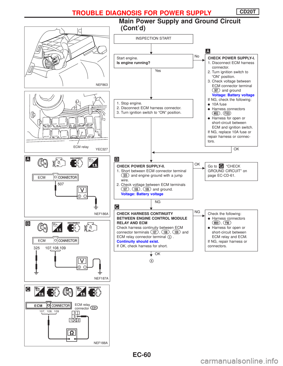
INSPECTION START
Start engine.
Is engine running?
Ye s
ENo
CHECK POWER SUPPLY-I.
1. Disconnect ECM harness
connector.
2. Turn ignition switch to
ªONº position.
3. Check voltage between
ECM connector terminal
507and ground
Voltage: Battery voltage
If NG, check the following:
l10A fuselHarness connectorsM52,F103
lHarness for open or
short-circuit between
ECM and ignition switch.
If NG, replace 10A fuse or
repair harness or connec-
tors.
OK 1. Stop engine.
2. Disconnect ECM harness connector.
3. Turn ignition switch to ªONº position.F
CHECK POWER SUPPLY-II.
1. Short between ECM connector terminal
325and engine ground with a jump
wire.
2. Check voltage between ECM terminals
107,108,109and ground.
Voltage: Battery voltage
NG
EOK
Go toªCHECK
GROUND CIRCUITº on
page EC-CD-61.
CHECK HARNESS CONTINUITY
BETWEEN ENGINE CONTROL MODULE
RELAY AND ECM
Check harness continuity between ECM
connector terminals
107,108,109and
ECM relay connector terminal
p5.
Continuity should exist.
If OK, check harness for short.
OK
ENG
Check the following:
lHarness connectorsM89,F96
lHarness for open or
short-circuit between
ECM relay and ECM.
If NG, repair harness or
connectors.
pA
NEF863
YEC327 ECM relay
NEF186A
NEF187A
NEF188A
ECM relay
connector
H
H
H
H
H
TROUBLE DIAGNOSIS FOR POWER SUPPLYCD20T
Main Power Supply and Ground Circuit
(Cont'd)
EC-60
Page 355 of 2267
pA
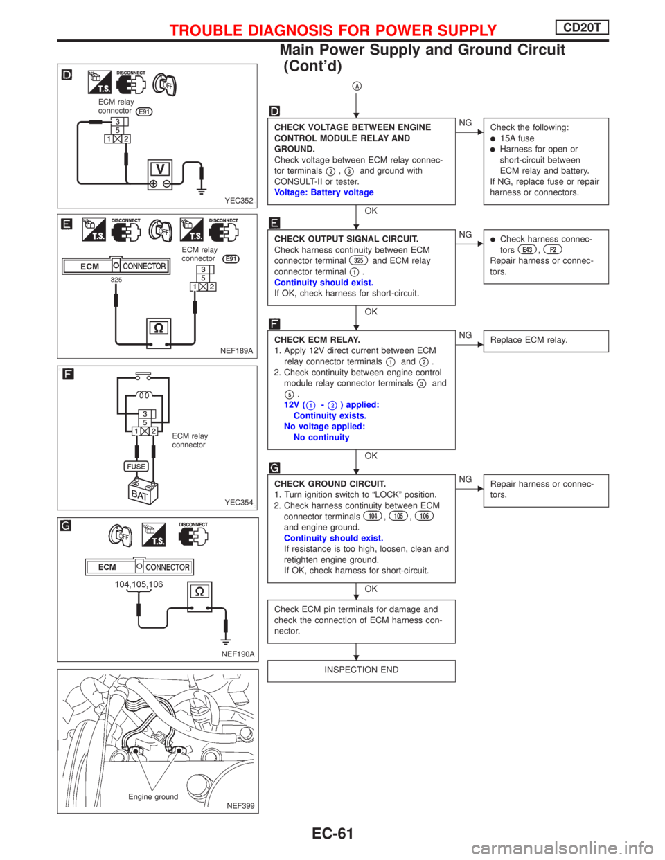
CHECK VOLTAGE BETWEEN ENGINE
CONTROL MODULE RELAY AND
GROUND.
Check voltage between ECM relay connec-
tor terminals
p2,p3and ground with
CONSULT-II or tester.
Voltage: Battery voltage
OK
ENG
Check the following:
l15A fuselHarness for open or
short-circuit between
ECM relay and battery.
If NG, replace fuse or repair
harness or connectors.
CHECK OUTPUT SIGNAL CIRCUIT.
Check harness continuity between ECM
connector terminal
325and ECM relay
connector terminal
p1.
Continuity should exist.
If OK, check harness for short-circuit.
OK
ENGlCheck harness connec-
torsE43,F2
Repair harness or connec-
tors.
CHECK ECM RELAY.
1. Apply 12V direct current between ECM
relay connector terminals
p1andp2.
2. Check continuity between engine control
module relay connector terminals
p3and
p5.
12V (
p1-p2) applied:
Continuity exists.
No voltage applied:
No continuity
OK
ENG
Replace ECM relay.
CHECK GROUND CIRCUIT.
1. Turn ignition switch to ªLOCKº position.
2. Check harness continuity between ECM
connector terminals
104,105,106
and engine ground.
Continuity should exist.
If resistance is too high, loosen, clean and
retighten engine ground.
If OK, check harness for short-circuit.
OK
ENG
Repair harness or connec-
tors.
Check ECM pin terminals for damage and
check the connection of ECM harness con-
nector.
INSPECTION END
YEC352 ECM relay
connector
NEF189A ECM relay
connector
YEC354 ECM relay
connector
NEF190A
NEF399 Engine ground
H
H
H
H
H
H
TROUBLE DIAGNOSIS FOR POWER SUPPLYCD20T
Main Power Supply and Ground Circuit
(Cont'd)
EC-61
Page 357 of 2267
YEC799
BATTERY
Refer to EL-POWER.: Detectable line for DTC
: Non-detectable line for DTC
ENGINE
CONTROL
MODULE
RELAYMASS AIR
FLOW SEN-
SOR
ECM
TROUBLE DIAGNOSIS 1CD20T
Mass Air Flow Sensor (MAFS) (Cont'd)
EC-63
Page 364 of 2267
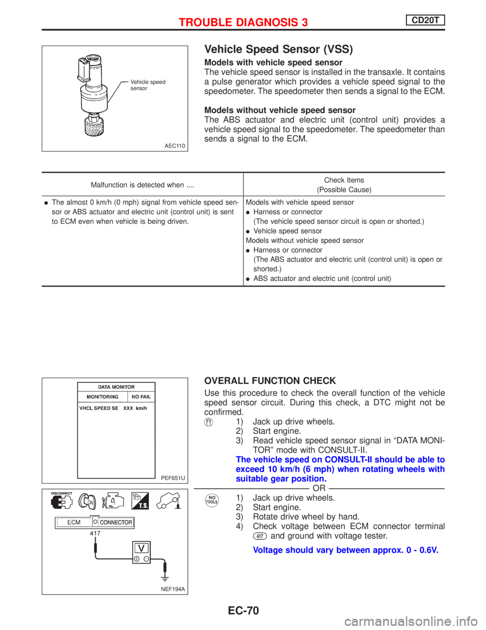
Vehicle Speed Sensor (VSS)
Models with vehicle speed sensor
The vehicle speed sensor is installed in the transaxle. It contains
a pulse generator which provides a vehicle speed signal to the
speedometer. The speedometer then sends a signal to the ECM.
Models without vehicle speed sensor
The ABS actuator and electric unit (control unit) provides a
vehicle speed signal to the speedometer. The speedometer than
sends a signal to the ECM.
Malfunction is detected when ....Check Items
(Possible Cause)
lThe almost 0 km/h (0 mph) signal from vehicle speed sen-
sor or ABS actuator and electric unit (control unit) is sent
to ECM even when vehicle is being driven.Models with vehicle speed sensor
lHarness or connector
(The vehicle speed sensor circuit is open or shorted.)
lVehicle speed sensor
Models without vehicle speed sensor
lHarness or connector
(The ABS actuator and electric unit (control unit) is open or
shorted.)
lABS actuator and electric unit (control unit)
OVERALL FUNCTION CHECK
Use this procedure to check the overall function of the vehicle
speed sensor circuit. During this check, a DTC might not be
confirmed.
1) Jack up drive wheels.
2) Start engine.
3) Read vehicle speed sensor signal in ªDATA MONI-
TORº mode with CONSULT-II.
The vehicle speed on CONSULT-II should be able to
exceed 10 km/h (6 mph) when rotating wheels with
suitable gear position.
--------------------------------------------------------------------------------------------------------------------------------------------------------------------------------------------------------------------------------------------------------------OR--------------------------------------------------------------------------------------------------------------------------------------------------------------------------------------------------------------------------------------------------------------
1) Jack up drive wheels.
2) Start engine.
3) Rotate drive wheel by hand.
4) Check voltage between ECM connector terminal
417and ground with voltage tester.
Voltage should vary between approx. 0 - 0.6V.
AEC110 Vehicle speed
sensor
PEF651U
NEF194A
TROUBLE DIAGNOSIS 3CD20T
EC-70
Page 367 of 2267
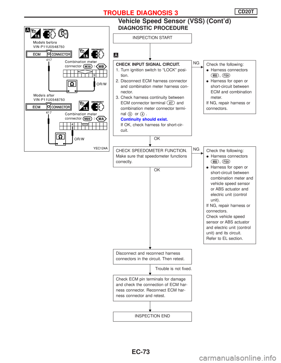
DIAGNOSTIC PROCEDURE
INSPECTION START
CHECK INPUT SIGNAL CIRCUIT.
1. Turn ignition switch to ªLOCKº posi-
tion.
2. Disconnect ECM harness connector
and combination meter harness con-
nector.
3. Check harness continuity between
ECM connector terminal
417and
combination meter connector termi-
nal
p9orp4.
Continuity should exist.
If OK, check harness for short-cir-
cuit.
OK
ENG
Check the following:
lHarness connectors
M50,F104
lHarness for open or
short-circuit between
ECM and combination
meter.
If NG, repair harness or
connectors.
CHECK SPEEDOMETER FUNCTION.
Make sure that speedometer functions
correctly.
OK
ENG
Check the following:
lHarness connectors
M50,F104
lHarness for open or
short-circuit between
combination meter and
vehicle speed sensor
or ABS actuator and
electric unit (control
unit).
If NG, repair harness or
connectors.
Check vehicle speed
sensor or ABS actuator
and electric unit (control
unit) and its circuit.
Refer to EL section.
Disconnect and reconnect harness
connectors in the circuit. Then retest.
Trouble is not fixed.
Check ECM pin terminals for damage
and check the connection of ECM har-
ness connector. Reconnect ECM har-
ness connector and retest.
INSPECTION END
YEC124A
H
H
H
H
H
TROUBLE DIAGNOSIS 3CD20T
Vehicle Speed Sensor (VSS) (Cont'd)
EC-73
Page 368 of 2267
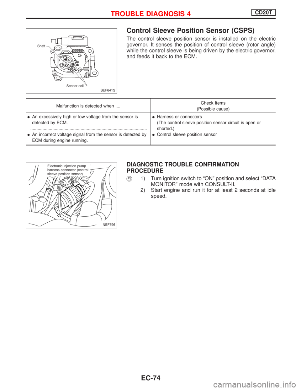
Control Sleeve Position Sensor (CSPS)
The control sleeve position sensor is installed on the electric
governor. It senses the position of control sleeve (rotor angle)
while the control sleeve is being driven by the electric governor,
and feeds it back to the ECM.
Malfunction is detected when ....Check Items
(Possible cause)
lAn excessively high or low voltage from the sensor is
detected by ECM.
...............................................................................................
lAn incorrect voltage signal from the sensor is detected by
ECM during engine running.
lHarness or connectors
(The control sleeve position sensor circuit is open or
shorted.)
lControl sleeve position sensor
DIAGNOSTIC TROUBLE CONFIRMATION
PROCEDURE
1) Turn ignition switch to ªONº position and select ªDATA
MONITORº mode with CONSULT-II.
2) Start engine and run it for at least 2 seconds at idle
speed.
SEF641S Shaft
Sensor coil
NEF796
.Electronic injection pump
harness connector (control
sleeve position sensor)
TROUBLE DIAGNOSIS 4CD20T
EC-74
Page 369 of 2267
YEC802
INJECTION PUMP (CON-
TROL SLEEVE POSITION
SENSOR)
: Detectable line for DTC
: Non-detectable line for DTC
ECM
TROUBLE DIAGNOSIS 4CD20T
Control Sleeve Position Sensor (CSPS)
(Cont'd)
EC-75
Page 370 of 2267
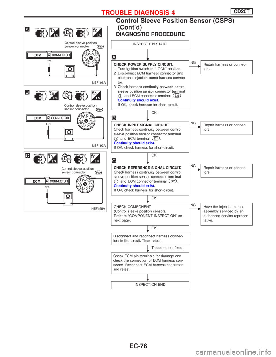
DIAGNOSTIC PROCEDURE
INSPECTION START
CHECK POWER SUPPLY CIRCUIT.
1. Turn ignition switch to ªLOCKº position.
2. Disconnect ECM harness connector and
electronic injection pump harness connec-
tor.
3. Check harness continuity between control
sleeve position sensor connector terminal
p3and ECM connector terminal320.
Continuity should exist.
If OK, check harness for short-circuit.
OK
ENG
Repair harness or connec-
tors.
CHECK INPUT SIGNAL CIRCUIT.
Check harness continuity between control
sleeve position sensor connector terminal
p2and ECM terminal321.
Continuity should exist.
If OK, check harness for short-circuit.
OK
ENG
Repair harness or connec-
tors.
CHECK REFERENCE SIGNAL CIRCUIT.
Check harness continuity between control
sleeve position sensor connector terminal
p1and ECM connector terminal322.
Continuity should exist.
If OK, check harness for short-circuit.
OK
ENG
Repair harness or connec-
tors.
CHECK COMPONENT
(Control sleeve position sensor).
Refer to ªCOMPONENT INSPECTIONº on
next page.
OK
ENG
Have the injection pump
assembly serviced by an
authorised service represen-
tative.
Disconnect and reconnect harness connec-
tors in the circuit. Then retest.
Trouble is not fixed.
Check ECM pin terminals for damage and
check the connection of ECM harness con-
nector. Reconnect ECM harness connector
and retest.
INSPECTION END
NEF196A
Control sleeve position
sensor connector
NEF197A
Control sleeve position
sensor connector
NEF198A
Control sleeve position
sensor connector
H
H
H
H
H
H
H
TROUBLE DIAGNOSIS 4CD20T
Control Sleeve Position Sensor (CSPS)
(Cont'd)
EC-76