1999 NISSAN PRIMERA Control
[x] Cancel search: ControlPage 423 of 2267
EGRC-Solenoid Valve
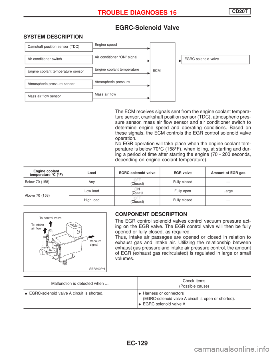
SYSTEM DESCRIPTION
Camshaft position sensor (TDC)EEngine speed
ECM
Air conditioner switchEAir conditioner ªONº signalEEGRC-solenoid valve
Engine coolant temperature sensorEEngine coolant temperature
Atmospheric pressure sensor
EAtmospheric pressure
Mass air flow sensor
EMass air flow
The ECM receives signals sent from the engine coolant tempera-
ture sensor, crankshaft position sensor (TDC), atmospheric pres-
sure sensor, mass air flow sensor and air conditioner switch to
determine engine speed and operating conditions. Based on
these signals, the ECM controls the EGR control solenoid valve
operation.
No EGR operation will take place when the engine coolant tem-
perature is below 70ÉC (158ÉF), when idling, at starting and dur-
ing a period of time after starting the engine (70 - 200 seconds,
depending on engine coolant temperature).
Engine coolant
temperature ÉC (ÉF)Load EGRC-solenoid valve EGR valve Amount of EGR gas
Below 70 (158) AnyOFF
(Closed)Fully closed Ð
Above 70 (158)Low loadON
(Open)Fully open Large
High loadOFF
(Closed)Fully closed Ð
COMPONENT DESCRIPTION
The EGR control solenoid valves control vacuum pressure act-
ing on the EGR valve. The EGR control valve will then be fully
opened or fully closed, as required.
Thus, intake air passages are opened or closed in relation to
exhaust gas and intake air. Utilizing the relationship between
exhaust gas pressure and intake air pressure control, the amount
of EGR (exhaust gas recirculated) is regulated in large or small
volumes.
Malfunction is detected when ....Check Items
(Possible cause)
lEGRC-solenoid valve A circuit is shorted.lHarness or connectors
(EGRC-solenoid valve A circuit is open or shorted).
lEGRC solenoid valve A
SEF240PH To control valve
To intake
air flow
Vacuum
signal
TROUBLE DIAGNOSES 16CD20T
EC-129
Page 425 of 2267
YEC814
BATTERY
Refer to EL-POWER.: Detectable line for DTC
: Non-detectable line for DTC
EGRC-
SOLENOID
VA LV E A ENGINE
CONTROL
MODULE
RELAY
ECM EGRC-
SOLENOID
VA LV E B
TROUBLE DIAGNOSES 16CD20T
EGRC-Solenoid Valve (Cont'd)
EC-131
Page 427 of 2267
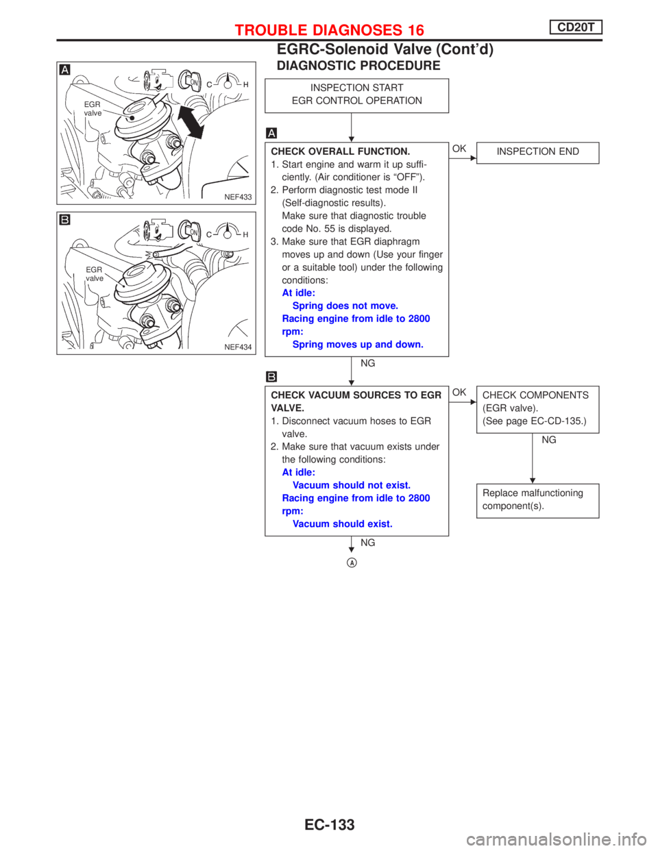
DIAGNOSTIC PROCEDURE
INSPECTION START
EGR CONTROL OPERATION
CHECK OVERALL FUNCTION.
1. Start engine and warm it up suffi-
ciently. (Air conditioner is ªOFFº).
2. Perform diagnostic test mode II
(Self-diagnostic results).
Make sure that diagnostic trouble
code No. 55 is displayed.
3. Make sure that EGR diaphragm
moves up and down (Use your finger
or a suitable tool) under the following
conditions:
At idle:
Spring does not move.
Racing engine from idle to 2800
rpm:
Spring moves up and down.
NG
EOK
INSPECTION END
CHECK VACUUM SOURCES TO EGR
VA LV E .
1. Disconnect vacuum hoses to EGR
valve.
2. Make sure that vacuum exists under
the following conditions:
At idle:
Vacuum should not exist.
Racing engine from idle to 2800
rpm:
Vacuum should exist.
NG
EOK
CHECK COMPONENTS
(EGR valve).
(See page EC-CD-135.)
NG
Replace malfunctioning
component(s).
pA
NEF433
EGR
valve
NEF434
EGR
valve
H
H
H
H
TROUBLE DIAGNOSES 16CD20T
EGRC-Solenoid Valve (Cont'd)
EC-133
Page 428 of 2267
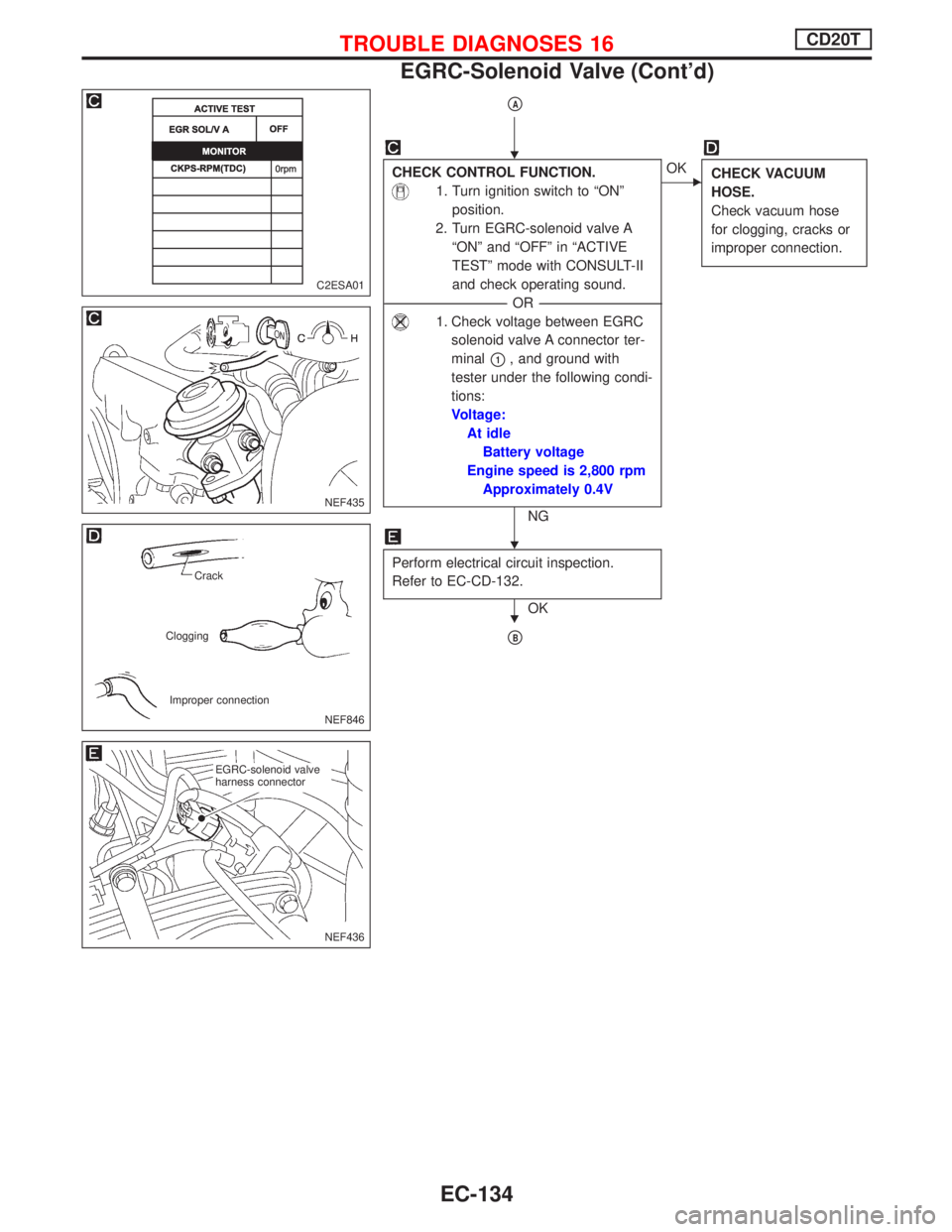
pA
CHECK CONTROL FUNCTION.
1. Turn ignition switch to ªONº
position.
2. Turn EGRC-solenoid valve A
ªONº and ªOFFº in ªACTIVE
TESTº mode with CONSULT-II
and check operating sound.
----------------------------------------------------------------------------------------------------------------------------------------OR----------------------------------------------------------------------------------------------------------------------------------------
1. Check voltage between EGRC
solenoid valve A connector ter-
minal
p1, and ground with
tester under the following condi-
tions:
Voltage:
At idle
Battery voltage
Engine speed is 2,800 rpm
Approximately 0.4V
NG
EOK
CHECK VACUUM
HOSE.
Check vacuum hose
for clogging, cracks or
improper connection.
Perform electrical circuit inspection.
Refer to EC-CD-132.
OK
pB
C2ESA01
NEF435
NEF846
Crack
Clogging
Improper connection
.
NEF436
.EGRC-solenoid valve
harness connector
H
H
H
TROUBLE DIAGNOSES 16CD20T
EGRC-Solenoid Valve (Cont'd)
EC-134
Page 441 of 2267
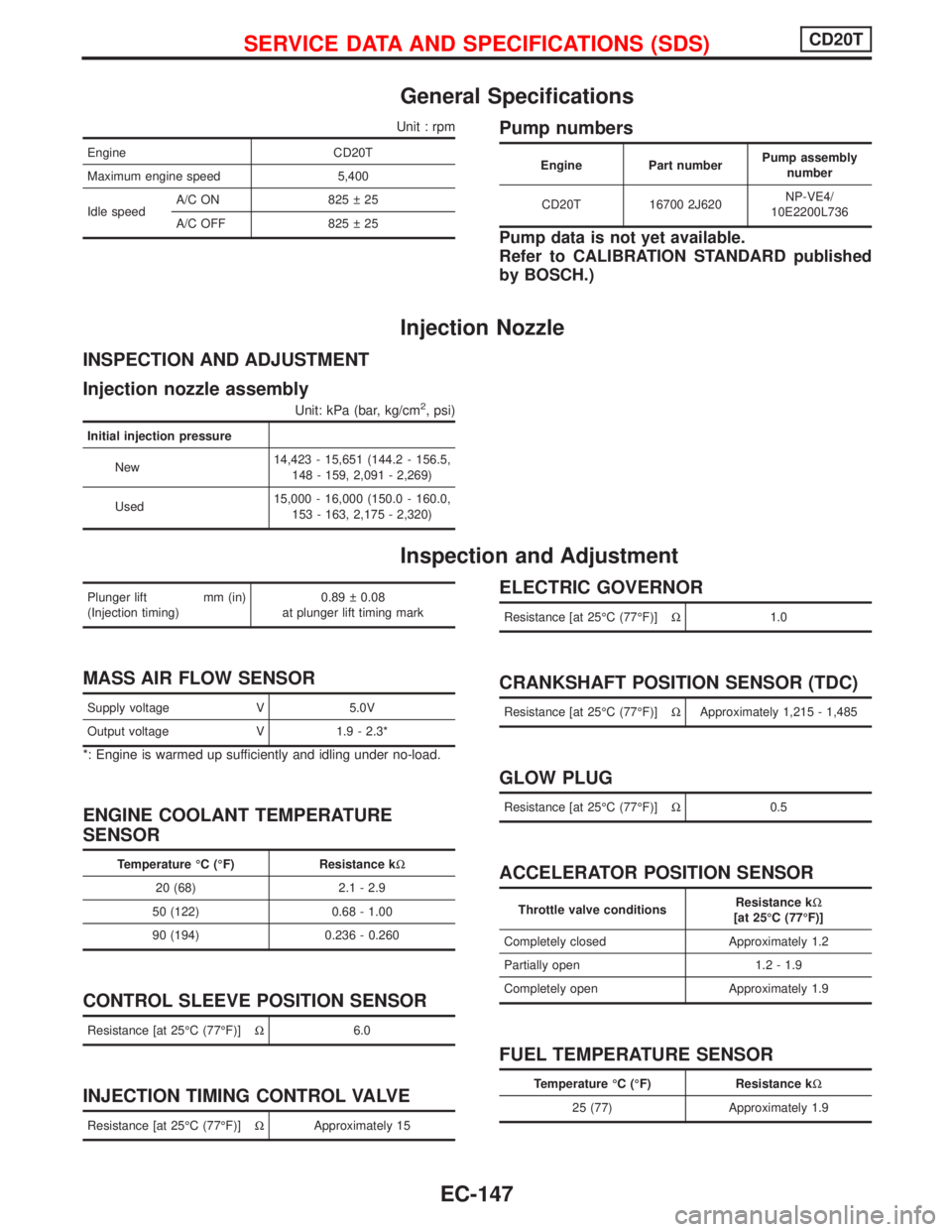
General Specifications
Unit : rpm
Engine CD20T
Maximum engine speed 5,400
Idle speedA/C ON 825 25
A/C OFF 825 25
Pump numbers
Engine Part numberPump assembly
number
CD20T 16700 2J620NP-VE4/
10E2200L736
Pump data is not yet available.
Refer to CALIBRATION STANDARD published
by BOSCH.)
Injection Nozzle
INSPECTION AND ADJUSTMENT
Injection nozzle assembly
Unit: kPa (bar, kg/cm2, psi)
Initial injection pressure
New14,423 - 15,651 (144.2 - 156.5,
148 - 159, 2,091 - 2,269)
Used15,000 - 16,000 (150.0 - 160.0,
153 - 163, 2,175 - 2,320)
Inspection and Adjustment
Plunger lift mm (in)
(Injection timing)0.89 0.08
at plunger lift timing mark
MASS AIR FLOW SENSOR
Supply voltage V 5.0V
Output voltage V 1.9 - 2.3*
*: Engine is warmed up sufficiently and idling under no-load.
ENGINE COOLANT TEMPERATURE
SENSOR
Temperature ÉC (ÉF) Resistance kW
20 (68) 2.1 - 2.9
50 (122) 0.68 - 1.00
90 (194) 0.236 - 0.260
CONTROL SLEEVE POSITION SENSOR
Resistance [at 25ÉC (77ÉF)]W6.0
INJECTION TIMING CONTROL VALVE
Resistance [at 25ÉC (77ÉF)]WApproximately 15
ELECTRIC GOVERNOR
Resistance [at 25ÉC (77ÉF)]W1.0
CRANKSHAFT POSITION SENSOR (TDC)
Resistance [at 25ÉC (77ÉF)]WApproximately 1,215 - 1,485
GLOW PLUG
Resistance [at 25ÉC (77ÉF)]W0.5
ACCELERATOR POSITION SENSOR
Throttle valve conditionsResistance kW
[at 25ÉC (77ÉF)]
Completely closed Approximately 1.2
Partially open 1.2 - 1.9
Completely open Approximately 1.9
FUEL TEMPERATURE SENSOR
Temperature ÉC (ÉF) Resistance kW
25 (77) Approximately 1.9
SERVICE DATA AND SPECIFICATIONS (SDS)CD20T
EC-147
Page 443 of 2267
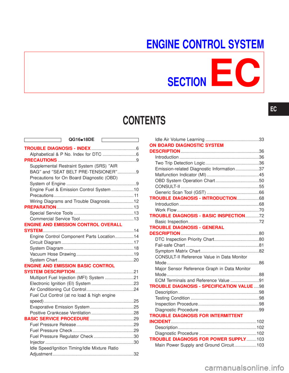
ENGINE CONTROL SYSTEM
SECTION
EC
CONTENTS
QG16I18DE
TROUBLE DIAGNOSIS - INDEX....................................6
Alphabetical & P No. Index for DTC ...........................6
PRECAUTIONS...............................................................9
Supplemental Restraint System (SRS)²AIR
BAG²and²SEAT BELT PRE-TENSIONER²...............9
Precautions for On Board Diagnostic (OBD)
System of Engine ........................................................9
Engine Fuel & Emission Control System ..................10
Precautions ................................................................ 11
Wiring Diagrams and Trouble Diagnosis ...................12
PREPARATION..............................................................13
Special Service Tools ................................................13
Commercial Service Tool ...........................................13
ENGINE AND EMISSION CONTROL OVERALL
SYSTEM.........................................................................14
Engine Control Component Parts Location ...............14
Circuit Diagram ..........................................................17
System Diagram ........................................................18
Vacuum Hose Drawing ..............................................19
System Chart .............................................................20
ENGINE AND EMISSION BASIC CONTROL
SYSTEM DESCRIPTION...............................................21
Multiport Fuel Injection (MFI) System .......................21
Electronic Ignition (EI) System ..................................23
Air Conditioning Cut Control ......................................24
Fuel Cut Control (at no load & high engine
speed) ........................................................................25
Evaporative Emission System ...................................25
Positive Crankcase Ventilation ..................................28
BASIC SERVICE PROCEDURE...................................29
Fuel Pressure Release ..............................................29
Fuel Pressure Check .................................................29
Fuel Pressure Regulator Check ................................30
Injector .......................................................................30
Idle Speed/Ignition Timing/Idle Mixture Ratio
Adjustment .................................................................32Idle Air Volume Learning ...........................................33
ON BOARD DIAGNOSTIC SYSTEM
DESCRIPTION...............................................................36
Introduction ................................................................36
Two Trip Detection Logic ...........................................36
Emission-related Diagnostic Information ...................37
Malfunction Indicator (MI) ..........................................45
OBD System Operation Chart ...................................50
CONSULT-II ...............................................................55
Generic Scan Tool (GST) ..........................................66
TROUBLE DIAGNOSIS - INTRODUCTION..................68
Introduction ................................................................68
Work Flow ..................................................................70
TROUBLE DIAGNOSIS - BASIC INSPECTION...........72
Basic Inspection.........................................................72
TROUBLE DIAGNOSIS - GENERAL
DESCRIPTION...............................................................80
DTC Inspection Priority Chart....................................80
Fail-safe Chart ...........................................................81
Symptom Matrix Chart ...............................................82
CONSULT-II Reference Value in Data Monitor
Mode ..........................................................................86
Major Sensor Reference Graph in Data Monitor
Mode ..........................................................................88
ECM Terminals and Reference Value .......................91
TROUBLE DIAGNOSIS - SPECIFICATION VALUE....98
Description .................................................................98
Testing Condition .......................................................98
Inspection Procedure .................................................98
Diagnostic Procedure ................................................99
TROUBLE DIAGNOSIS FOR INTERMITTENT
INCIDENT.....................................................................102
Description ...............................................................102
Diagnostic Procedure ..............................................102
TROUBLE DIAGNOSIS FOR POWER SUPPLY........103
Main Power Supply and Ground Circuit ..................103
EC
Page 446 of 2267
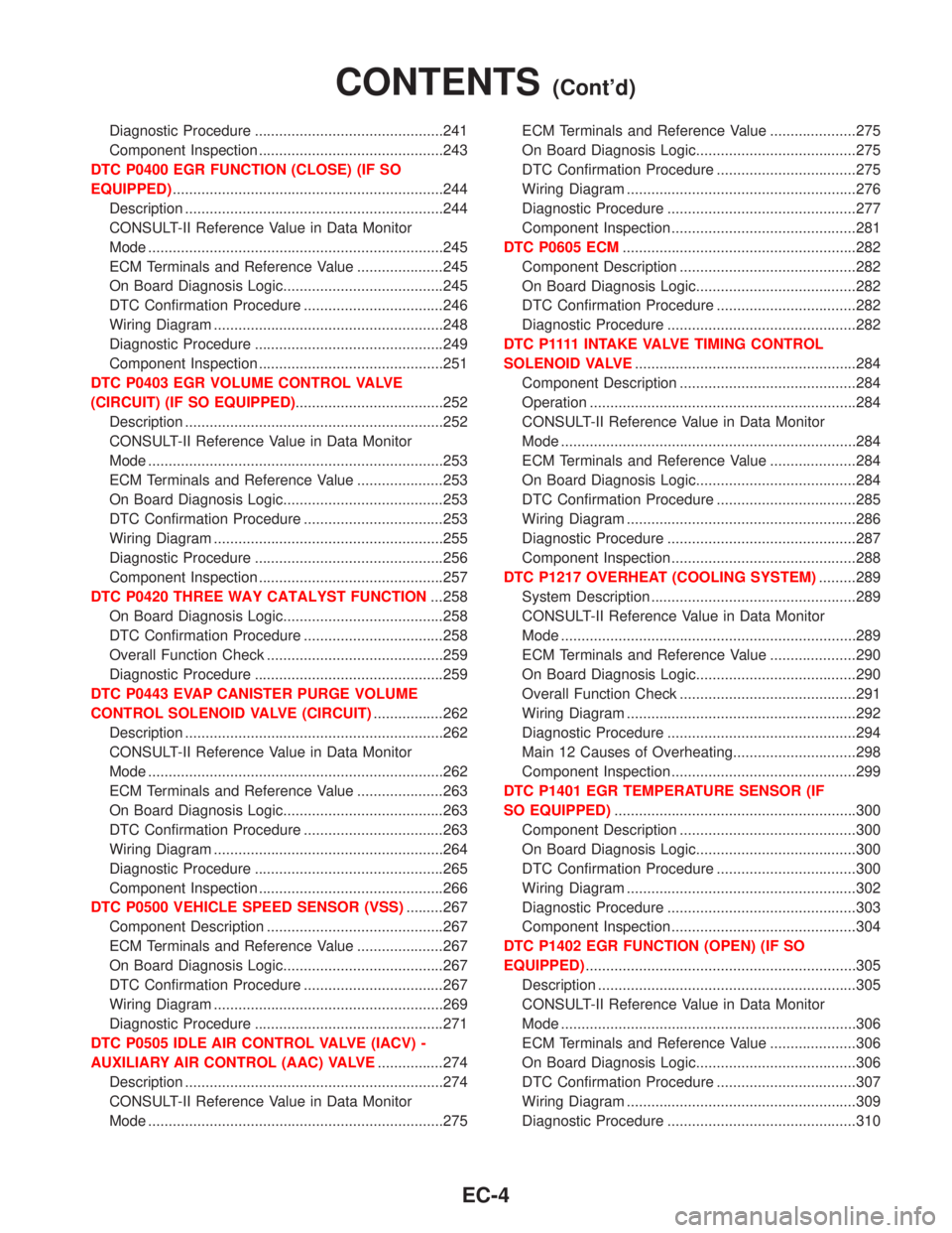
Diagnostic Procedure ..............................................241
Component Inspection .............................................243
DTC P0400 EGR FUNCTION (CLOSE) (IF SO
EQUIPPED)..................................................................244
Description ...............................................................244
CONSULT-II Reference Value in Data Monitor
Mode ........................................................................245
ECM Terminals and Reference Value .....................245
On Board Diagnosis Logic.......................................245
DTC Confirmation Procedure ..................................246
Wiring Diagram ........................................................248
Diagnostic Procedure ..............................................249
Component Inspection .............................................251
DTC P0403 EGR VOLUME CONTROL VALVE
(CIRCUIT) (IF SO EQUIPPED)....................................252
Description ...............................................................252
CONSULT-II Reference Value in Data Monitor
Mode ........................................................................253
ECM Terminals and Reference Value .....................253
On Board Diagnosis Logic.......................................253
DTC Confirmation Procedure ..................................253
Wiring Diagram ........................................................255
Diagnostic Procedure ..............................................256
Component Inspection .............................................257
DTC P0420 THREE WAY CATALYST FUNCTION...258
On Board Diagnosis Logic.......................................258
DTC Confirmation Procedure ..................................258
Overall Function Check ...........................................259
Diagnostic Procedure ..............................................259
DTC P0443 EVAP CANISTER PURGE VOLUME
CONTROL SOLENOID VALVE (CIRCUIT).................262
Description ...............................................................262
CONSULT-II Reference Value in Data Monitor
Mode ........................................................................262
ECM Terminals and Reference Value .....................263
On Board Diagnosis Logic.......................................263
DTC Confirmation Procedure ..................................263
Wiring Diagram ........................................................264
Diagnostic Procedure ..............................................265
Component Inspection .............................................266
DTC P0500 VEHICLE SPEED SENSOR (VSS).........267
Component Description ...........................................267
ECM Terminals and Reference Value .....................267
On Board Diagnosis Logic.......................................267
DTC Confirmation Procedure ..................................267
Wiring Diagram ........................................................269
Diagnostic Procedure ..............................................271
DTC P0505 IDLE AIR CONTROL VALVE (IACV) -
AUXILIARY AIR CONTROL (AAC) VALVE................274
Description ...............................................................274
CONSULT-II Reference Value in Data Monitor
Mode ........................................................................275ECM Terminals and Reference Value .....................275
On Board Diagnosis Logic.......................................275
DTC Confirmation Procedure ..................................275
Wiring Diagram ........................................................276
Diagnostic Procedure ..............................................277
Component Inspection .............................................281
DTC P0605 ECM.........................................................282
Component Description ...........................................282
On Board Diagnosis Logic.......................................282
DTC Confirmation Procedure ..................................282
Diagnostic Procedure ..............................................282
D T C P 1111 I N TA K E VA LV ETIMING CONTROL
SOLENOID VALVE......................................................284
Component Description ...........................................284
Operation .................................................................284
CONSULT-II Reference Value in Data Monitor
Mode ........................................................................284
ECM Terminals and Reference Value .....................284
On Board Diagnosis Logic.......................................284
DTC Confirmation Procedure ..................................285
Wiring Diagram ........................................................286
Diagnostic Procedure ..............................................287
Component Inspection .............................................288
DTC P1217 OVERHEAT (COOLING SYSTEM).........289
System Description ..................................................289
CONSULT-II Reference Value in Data Monitor
Mode ........................................................................289
ECM Terminals and Reference Value .....................290
On Board Diagnosis Logic.......................................290
Overall Function Check ...........................................291
Wiring Diagram ........................................................292
Diagnostic Procedure ..............................................294
Main 12 Causes of Overheating..............................298
Component Inspection .............................................299
DTC P1401 EGR TEMPERATURE SENSOR (IF
SO EQUIPPED)...........................................................300
Component Description ...........................................300
On Board Diagnosis Logic.......................................300
DTC Confirmation Procedure ..................................300
Wiring Diagram ........................................................302
Diagnostic Procedure ..............................................303
Component Inspection .............................................304
DTC P1402 EGR FUNCTION (OPEN) (IF SO
EQUIPPED)..................................................................305
Description ...............................................................305
CONSULT-II Reference Value in Data Monitor
Mode ........................................................................306
ECM Terminals and Reference Value .....................306
On Board Diagnosis Logic.......................................306
DTC Confirmation Procedure ..................................307
Wiring Diagram ........................................................309
Diagnostic Procedure ..............................................310
CONTENTS(Cont'd)
EC-4
Page 447 of 2267
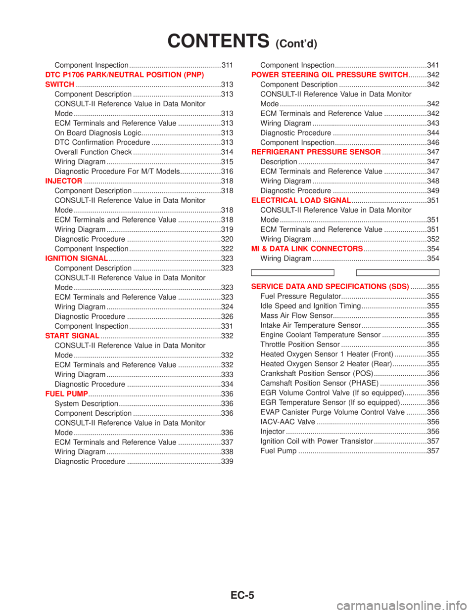
Component Inspection ............................................. 311
DTC P1706 PARK/NEUTRAL POSITION (PNP)
SWITCH.......................................................................313
Component Description ...........................................313
CONSULT-II Reference Value in Data Monitor
Mode ........................................................................313
ECM Terminals and Reference Value .....................313
On Board Diagnosis Logic.......................................313
DTC Confirmation Procedure ..................................313
Overall Function Check ...........................................314
Wiring Diagram ........................................................315
Diagnostic Procedure For M/T Models....................316
INJECTOR...................................................................318
Component Description ...........................................318
CONSULT-II Reference Value in Data Monitor
Mode ........................................................................318
ECM Terminals and Reference Value .....................318
Wiring Diagram ........................................................319
Diagnostic Procedure ..............................................320
Component Inspection .............................................322
IGNITION SIGNAL.......................................................323
Component Description ...........................................323
CONSULT-II Reference Value in Data Monitor
Mode ........................................................................323
ECM Terminals and Reference Value .....................323
Wiring Diagram ........................................................324
Diagnostic Procedure ..............................................326
Component Inspection .............................................331
START SIGNAL...........................................................332
CONSULT-II Reference Value in Data Monitor
Mode ........................................................................332
ECM Terminals and Reference Value .....................332
Wiring Diagram ........................................................333
Diagnostic Procedure ..............................................334
FUEL PUMP.................................................................336
System Description ..................................................336
Component Description ...........................................336
CONSULT-II Reference Value in Data Monitor
Mode ........................................................................336
ECM Terminals and Reference Value .....................337
Wiring Diagram ........................................................338
Diagnostic Procedure ..............................................339Component Inspection .............................................341
POWER STEERING OIL PRESSURE SWITCH.........342
Component Description ...........................................342
CONSULT-II Reference Value in Data Monitor
Mode ........................................................................342
ECM Terminals and Reference Value .....................342
Wiring Diagram ........................................................343
Diagnostic Procedure ..............................................344
Component Inspection .............................................346
REFRIGERANT PRESSURE SENSOR......................347
Description ...............................................................347
ECM Terminals and Reference Value .....................347
Wiring Diagram ........................................................348
Diagnostic Procedure ..............................................349
ELECTRICAL LOAD SIGNAL.....................................351
CONSULT-II Reference Value in Data Monitor
Mode ........................................................................351
ECM Terminals and Reference Value .....................351
Wiring Diagram ........................................................352
MI & DATA LINK CONNECTORS...............................354
Wiring Diagram ........................................................354
SERVICE DATA AND SPECIFICATIONS (SDS)........355
Fuel Pressure Regulator..........................................355
Idle Speed and Ignition Timing ................................355
Mass Air Flow Sensor..............................................355
Intake Air Temperature Sensor ................................355
Engine Coolant Temperature Sensor ......................355
Throttle Position Sensor ..........................................355
Heated Oxygen Sensor 1 Heater (Front) ................355
Heated Oxygen Sensor 2 Heater (Rear).................355
Crankshaft Position Sensor (POS) ..........................356
Camshaft Position Sensor (PHASE) .......................356
EGR Volume Control Valve (If so equipped)...........356
EGR Temperature Sensor (If so equipped).............356
EVAP Canister Purge Volume Control Valve ..........356
IACV-AAC Valve ......................................................356
Injector .....................................................................356
Ignition Coil with Power Transistor ..........................357
Fuel Pump ...............................................................357
CONTENTS(Cont'd)
EC-5