1999 NISSAN PRIMERA Control
[x] Cancel search: ControlPage 469 of 2267
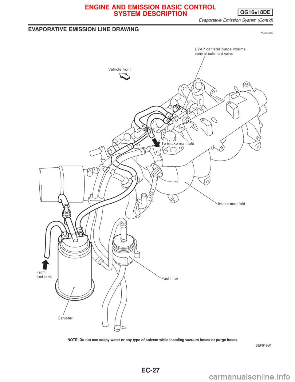
EVAPORATIVE EMISSION LINE DRAWINGNCEC0020
SEF919W
ENGINE AND EMISSION BASIC CONTROL
SYSTEM DESCRIPTIONQG16I18DE
Evaporative Emission System (Cont'd)
EC-27
Page 470 of 2267
Positive Crankcase Ventilation
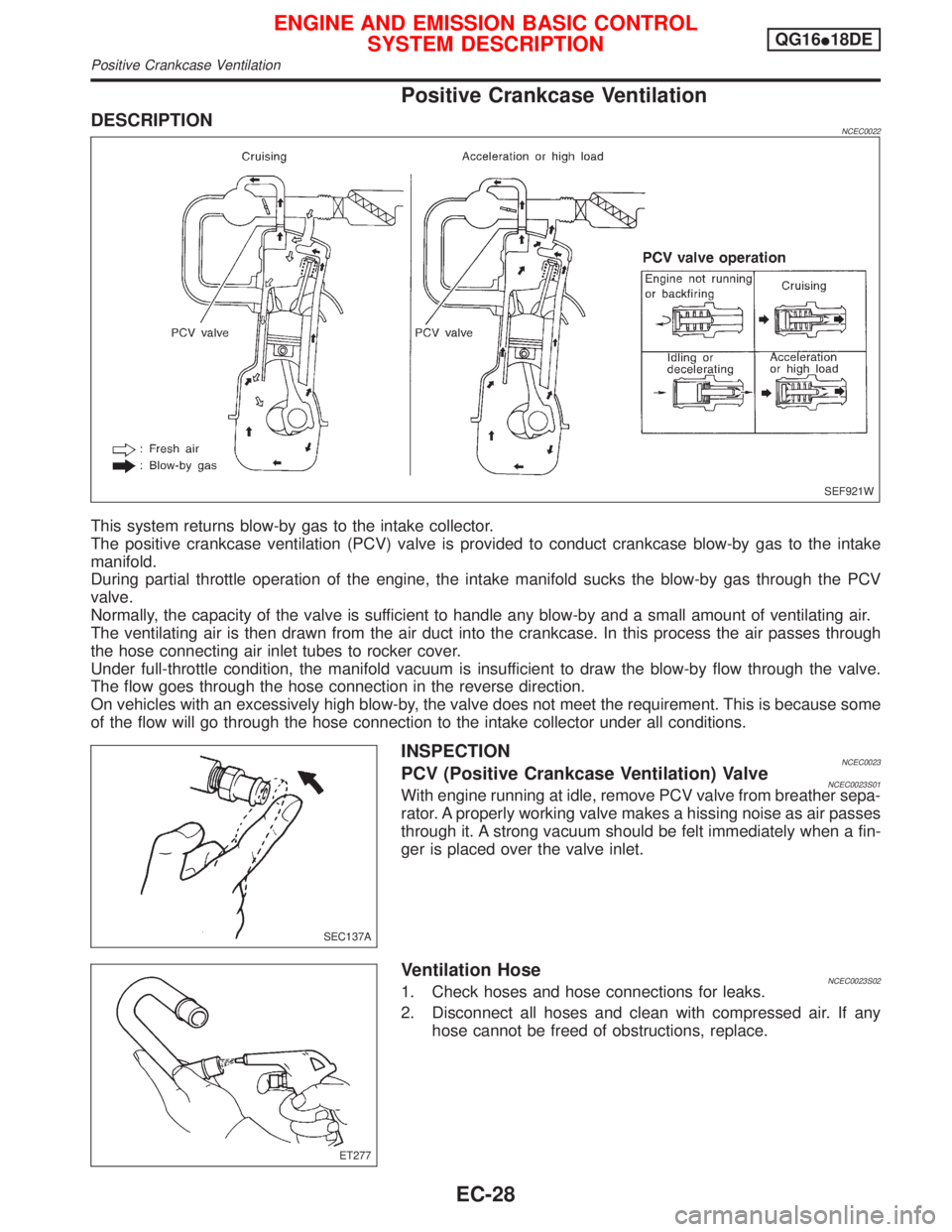
DESCRIPTIONNCEC0022
This system returns blow-by gas to the intake collector.
The positive crankcase ventilation (PCV) valve is provided to conduct crankcase blow-by gas to the intake
manifold.
During partial throttle operation of the engine, the intake manifold sucks the blow-by gas through the PCV
valve.
Normally, the capacity of the valve is sufficient to handle any blow-by and a small amount of ventilating air.
The ventilating air is then drawn from the air duct into the crankcase. In this process the air passes through
the hose connecting air inlet tubes to rocker cover.
Under full-throttle condition, the manifold vacuum is insufficient to draw the blow-by flow through the valve.
The flow goes through the hose connection in the reverse direction.
On vehicles with an excessively high blow-by, the valve does not meet the requirement. This is because some
of the flow will go through the hose connection to the intake collector under all conditions.
INSPECTIONNCEC0023PCV (Positive Crankcase Ventilation) ValveNCEC0023S01With engine running at idle, remove PCV valve from breather sepa-
rator. A properly working valve makes a hissing noise as air passes
through it. A strong vacuum should be felt immediately when a fin-
ger is placed over the valve inlet.
Ventilation HoseNCEC0023S021. Check hoses and hose connections for leaks.
2. Disconnect all hoses and clean with compressed air. If any
hose cannot be freed of obstructions, replace.
SEF921W
SEC137A
ET277
ENGINE AND EMISSION BASIC CONTROL
SYSTEM DESCRIPTIONQG16I18DE
Positive Crankcase Ventilation
EC-28
Page 479 of 2267
Emission-related Diagnostic InformationNCEC0031DTC AND 1ST TRIP DTCNCEC0031S01The 1st trip DTC (whose number is the same as the DTC number) is displayed for the latest self-diagnostic
result obtained. If the ECM memory was cleared previously, and the 1st trip DTC did not reoccur, the 1st trip
DTC will not be displayed. If a malfunction is detected during the 1st trip, the 1st trip DTC is stored in the ECM
memory. The MI will not light up (two trip detection logic). If the same malfunction is not detected in the 2nd
trip (meeting the required driving pattern), the 1st trip DTC is cleared from the ECM memory. If the same mal-
function is detected in the 2nd trip, both the 1st trip DTC and DTC are stored in the ECM memory and the MI
lights up. In other words, the DTC is stored in the ECM memory and the MI lights up when the same malfunc-
tion occurs in two consecutive trips. If a 1st trip DTC is stored and a non-diagnostic operation is performed
between the 1st and 2nd trips, only the 1st trip DTC will continue to be stored. For malfunctions that blink or
light up the MI during the 1st trip, the DTC and 1st trip DTC are stored in the ECM memory.
Procedures for clearing the DTC and the 1st trip DTC from the ECM memory are described in ªHOW TO
ERASE EMISSION-RELATED DIAGNOSTIC INFORMATIONº. Refer to EC-QG-44.
For malfunctions in which 1st trip DTCs are displayed, refer to EC-QG-42. These items are required by legal
regulations to continuously monitor the system/component. In addition, the items monitored non-continuously
are also displayed on CONSULT-II.
1st trip DTC is specified in Mode 7 of ISO15031-5. 1st trip DTC detection occurs without lighting up the MI
and therefore does not warn the driver of a problem. However, 1st trip DTC detection will not prevent the
vehicle from being tested, for example during Inspection/Maintenance (I/M) tests.
When a 1st trip DTC is detected, check, print out or write down and erase (1st trip) DTC and Freeze Frame
data as specified in ªWork Flowº procedure Step II, refer to page EC-QG-70. Then perform ªDTC Confirma-
tion Procedureº or ªOverall Function Checkº to try to duplicate the problem. If the malfunction is duplicated,
the item requires repair.
How to read DTC and 1st Trip DTCNCEC0031S0101DTC and 1st trip DTC can be read by the following methods.
1)
No Tools
The number of blinks of MI in the Diagnostic Test Mode II (Self-Diagnostic Results) Examples: 0340, 1320,
0705, 0750, etc.
These DTCs are controlled by NISSAN.
2)
With CONSULT-II
With GST
CONSULT-II or GST (Generic Scan Tool) Examples: P0340, P1320, P0705, P0750, etc.
These DTCs are prescribed by ISO15031-6.
(CONSULT-II also displays the malfunctioning component or system.)
I1st trip DTC No. is the same as DTC No.
IOutput of a DTC indicates a malfunction. However, Mode II and GST do not indicate whether the
malfunction is still occurring or has occurred in the past and has returned to normal.
CONSULT-II can identify malfunction status as shown below. Therefore, using CONSULT-II (if avail-
able) is recommended.
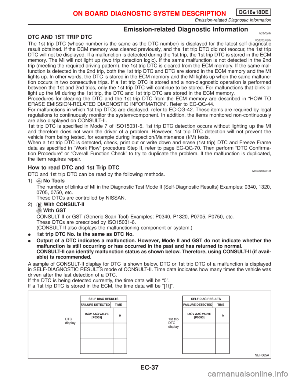
A sample of CONSULT-II display for DTC is shown below. DTC or 1st trip DTC of a malfunction is displayed
in SELF-DIAGNOSTIC RESULTS mode of CONSULT-II. Time data indicates how many times the vehicle was
driven after the last detection of a DTC.
If the DTC is being detected currently, the time data will be ª0º.
If a 1st trip DTC is stored in the ECM, the time data will be ª[1t]º.
NEF065A DTC
display1st trip
DTC
display
ON BOARD DIAGNOSTIC SYSTEM DESCRIPTIONQG16I18DE
Emission-related Diagnostic Information
EC-37
Page 481 of 2267
Together with the DTC, the SRT code is cleared from the ECM memory using the method described later
(Refer to EC-QG-44). In addition, after engine control components/system are repaired or if the battery termi-
nals remain disconnected for more than 24 hours, all SRT codes may be cleared from the ECM memory.
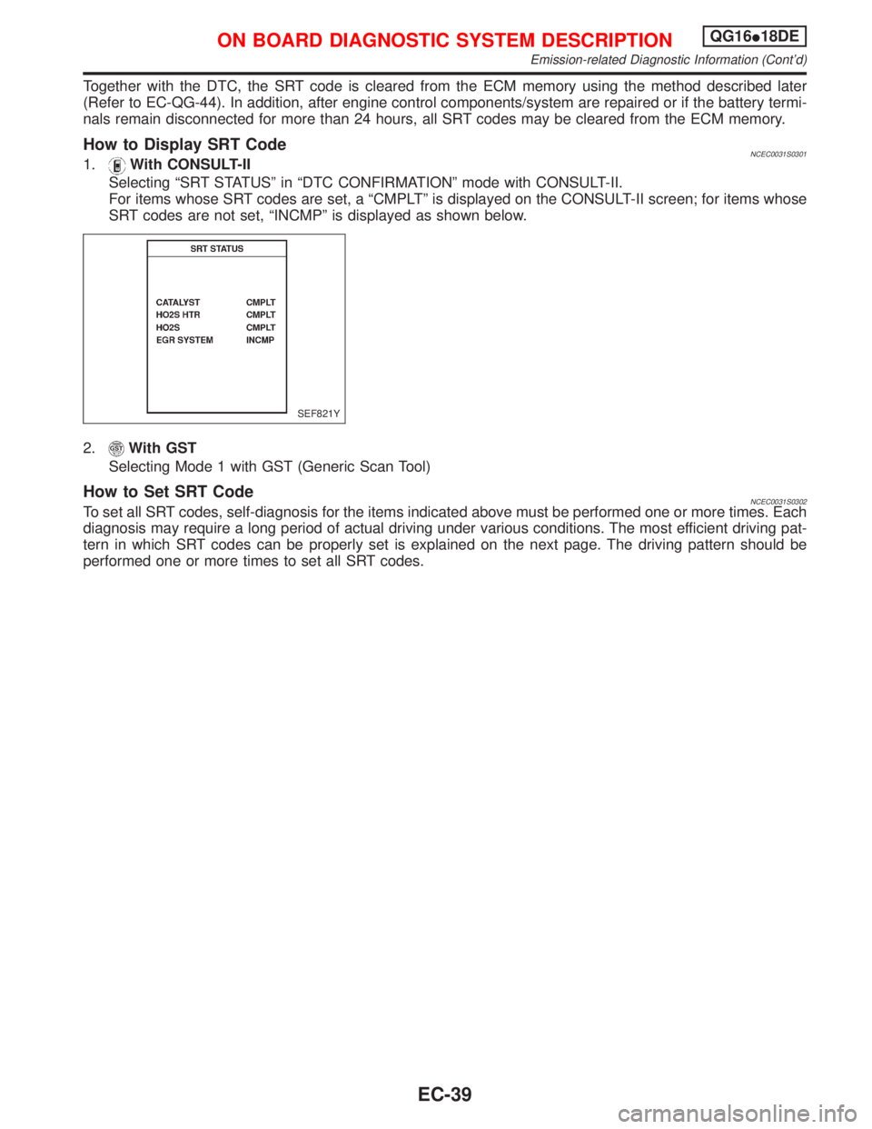
How to Display SRT CodeNCEC0031S03011.With CONSULT-II
Selecting ªSRT STATUSº in ªDTC CONFIRMATIONº mode with CONSULT-II.
For items whose SRT codes are set, a ªCMPLTº is displayed on the CONSULT-II screen; for items whose
SRT codes are not set, ªINCMPº is displayed as shown below.
2.
With GST
Selecting Mode 1 with GST (Generic Scan Tool)
How to Set SRT CodeNCEC0031S0302To set all SRT codes, self-diagnosis for the items indicated above must be performed one or more times. Each
diagnosis may require a long period of actual driving under various conditions. The most efficient driving pat-
tern in which SRT codes can be properly set is explained on the next page. The driving pattern should be
performed one or more times to set all SRT codes.
SEF821Y
ON BOARD DIAGNOSTIC SYSTEM DESCRIPTIONQG16I18DE
Emission-related Diagnostic Information (Cont'd)
EC-39
Page 485 of 2267
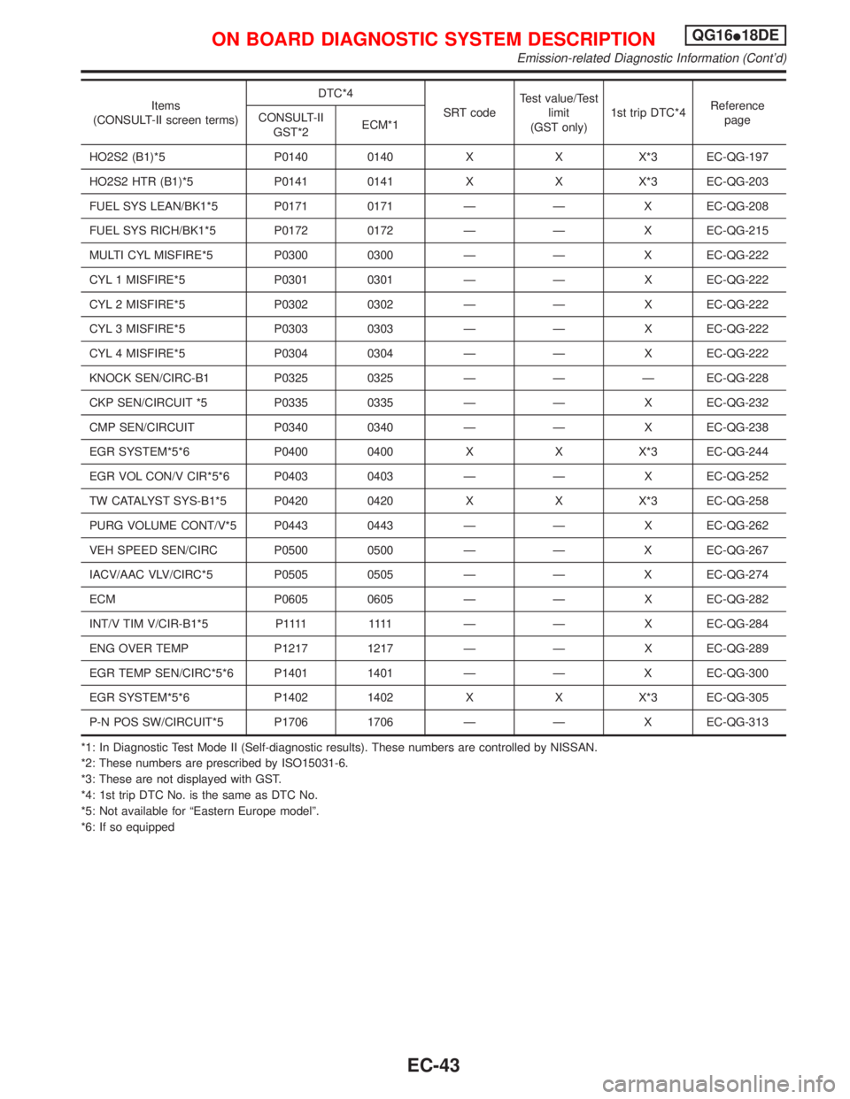
Items
(CONSULT-II screen terms)DTC*4
SRT codeTest value/Test
limit
(GST only)1st trip DTC*4Reference
page CONSULT-II
GST*2ECM*1
HO2S2 (B1)*5 P0140 0140 X X X*3 EC-QG-197
HO2S2 HTR (B1)*5 P0141 0141 X X X*3 EC-QG-203
FUEL SYS LEAN/BK1*5 P0171 0171 Ð Ð X EC-QG-208
FUEL SYS RICH/BK1*5 P0172 0172 Ð Ð X EC-QG-215
MULTI CYL MISFIRE*5 P0300 0300 Ð Ð X EC-QG-222
CYL 1 MISFIRE*5 P0301 0301 Ð Ð X EC-QG-222
CYL 2 MISFIRE*5 P0302 0302 Ð Ð X EC-QG-222
CYL 3 MISFIRE*5 P0303 0303 Ð Ð X EC-QG-222
CYL 4 MISFIRE*5 P0304 0304 Ð Ð X EC-QG-222
KNOCK SEN/CIRC-B1 P0325 0325 Ð Ð Ð EC-QG-228
CKP SEN/CIRCUIT *5 P0335 0335 Ð Ð X EC-QG-232
CMP SEN/CIRCUIT P0340 0340 Ð Ð X EC-QG-238
EGR SYSTEM*5*6 P0400 0400 X X X*3 EC-QG-244
EGR VOL CON/V CIR*5*6 P0403 0403 Ð Ð X EC-QG-252
TW CATALYST SYS-B1*5 P0420 0420 X X X*3 EC-QG-258
PURG VOLUME CONT/V*5 P0443 0443 Ð Ð X EC-QG-262
VEH SPEED SEN/CIRC P0500 0500 Ð Ð X EC-QG-267
IACV/AAC VLV/CIRC*5 P0505 0505 Ð Ð X EC-QG-274
ECM P0605 0605 Ð Ð X EC-QG-282
INT/V TIM V/CIR-B1*5 P1111 1111 Ð Ð XEC-QG-284
ENG OVER TEMP P1217 1217 Ð Ð X EC-QG-289
EGR TEMP SEN/CIRC*5*6 P1401 1401 Ð Ð X EC-QG-300
EGR SYSTEM*5*6 P1402 1402 X X X*3 EC-QG-305
P-N POS SW/CIRCUIT*5 P1706 1706 Ð Ð X EC-QG-313
*1: In Diagnostic Test Mode II (Self-diagnostic results). These numbers are controlled by NISSAN.
*2: These numbers are prescribed by ISO15031-6.
*3: These are not displayed with GST.
*4: 1st trip DTC No. is the same as DTC No.
*5: Not available for ªEastern Europe modelº.
*6: If so equipped
ON BOARD DIAGNOSTIC SYSTEM DESCRIPTIONQG16I18DE
Emission-related Diagnostic Information (Cont'd)
EC-43
Page 492 of 2267
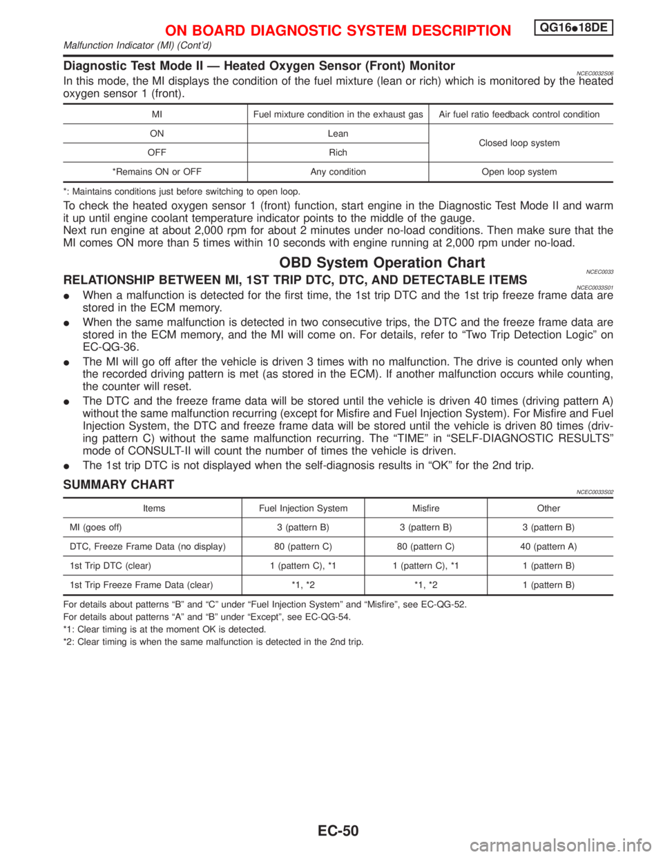
Diagnostic Test Mode II Ð Heated Oxygen Sensor (Front) MonitorNCEC0032S06In this mode, the MI displays the condition of the fuel mixture (lean or rich) which is monitored by the heated
oxygen sensor 1 (front).
MI Fuel mixture condition in the exhaust gas Air fuel ratio feedback control condition
ON Lean
Closed loop system
OFF Rich
*Remains ON or OFF Any condition Open loop system
*: Maintains conditions just before switching to open loop.
To check the heated oxygen sensor 1 (front) function, start engine in the Diagnostic Test Mode II and warm
it up until engine coolant temperature indicator points to the middle of the gauge.
Next run engine at about 2,000 rpm for about 2 minutes under no-load conditions. Then make sure that the
MI comes ON more than 5 times within 10 seconds with engine running at 2,000 rpm under no-load.
OBD System Operation ChartNCEC0033RELATIONSHIP BETWEEN MI, 1ST TRIP DTC, DTC, AND DETECTABLE ITEMSNCEC0033S01IWhen a malfunction is detected for the first time, the 1st trip DTC and the 1st trip freeze frame data are
stored in the ECM memory.
IWhen the same malfunction is detected in two consecutive trips, the DTC and the freeze frame data are
stored in the ECM memory, and the MI will come on. For details, refer to ªTwo Trip Detection Logicº on
EC-QG-36.
IThe MI will go off after the vehicle is driven 3 times with no malfunction. The drive is counted only when
the recorded driving pattern is met (as stored in the ECM). If another malfunction occurs while counting,
the counter will reset.
IThe DTC and the freeze frame data will be stored until the vehicle is driven 40 times (driving pattern A)
without the same malfunction recurring (except for Misfire and Fuel Injection System). For Misfire and Fuel
Injection System, the DTC and freeze frame data will be stored until the vehicle is driven 80 times (driv-
ing pattern C) without the same malfunction recurring. The ªTIMEº in ªSELF-DIAGNOSTIC RESULTSº
mode of CONSULT-II will count the number of times the vehicle is driven.
IThe 1st trip DTC is not displayed when the self-diagnosis results in ªOKº for the 2nd trip.
SUMMARY CHARTNCEC0033S02
Items Fuel Injection System Misfire Other
MI (goes off) 3 (pattern B) 3 (pattern B) 3 (pattern B)
DTC, Freeze Frame Data (no display) 80 (pattern C) 80 (pattern C) 40 (pattern A)
1st Trip DTC (clear) 1 (pattern C), *1 1 (pattern C), *1 1 (pattern B)
1st Trip Freeze Frame Data (clear) *1, *2 *1, *2 1 (pattern B)
For details about patterns ªBº and ªCº under ªFuel Injection Systemº and ªMisfireº, see EC-QG-52.
For details about patterns ªAº and ªBº under ªExceptº, see EC-QG-54.
*1: Clear timing is at the moment OK is detected.
*2: Clear timing is when the same malfunction is detected in the 2nd trip.
ON BOARD DIAGNOSTIC SYSTEM DESCRIPTIONQG16I18DE
Malfunction Indicator (MI) (Cont'd)
EC-50
Page 498 of 2267
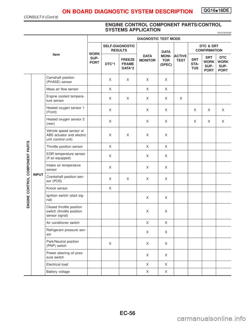
ENGINE CONTROL COMPONENT PARTS/CONTROL
SYSTEMS APPLICATION
NCEC0034S02
ItemDIAGNOSTIC TEST MODE
WORK
SUP-
PORTSELF-DIAGNOSTIC
RESULTS
D ATA
MONITORD ATA
MONI-
TOR
(SPEC)ACTIVE
TESTDTC & SRT
CONFIRMATION
DTC*1FREEZE
FRAME
DATA*2SRT
STA-
TUSSRT
WORK
SUP-
PORTDTC
WORK
SUP-
PORT
ENGINE CONTROL COMPONENT PARTS
INPUTCamshaft position
(PHASE) sensorXX X X
Mass air flow sensor X X X
Engine coolant tempera-
ture sensorXX X XX
Heated oxygen sensor 1
(Front)X X X XXX
Heated oxygen sensor 2
(rear)X X X XXX
Vehicle speed sensor or
ABS actuator and electric
unit (control unit)XX X X
Throttle position sensor X X X
EGR temperature sensor
(If so equipped)XXX
Intake air temperature
sensorXXX
Crankshaft position sen-
sor (POS)XX X X
Knock sensor X
Ignition switch (start sig-
nal)XX
Closed throttle position
switch (throttle position
sensor signal)XX
Air conditioner switch X X
Refrigerant pressure sen-
sorXX
Park/Neutral position
(PNP) switchXXX
Power steering oil pres-
sure switchXX
Electrical load X X
Battery voltage X X
ON BOARD DIAGNOSTIC SYSTEM DESCRIPTIONQG16I18DE
CONSULT-II (Cont'd)
EC-56
Page 499 of 2267
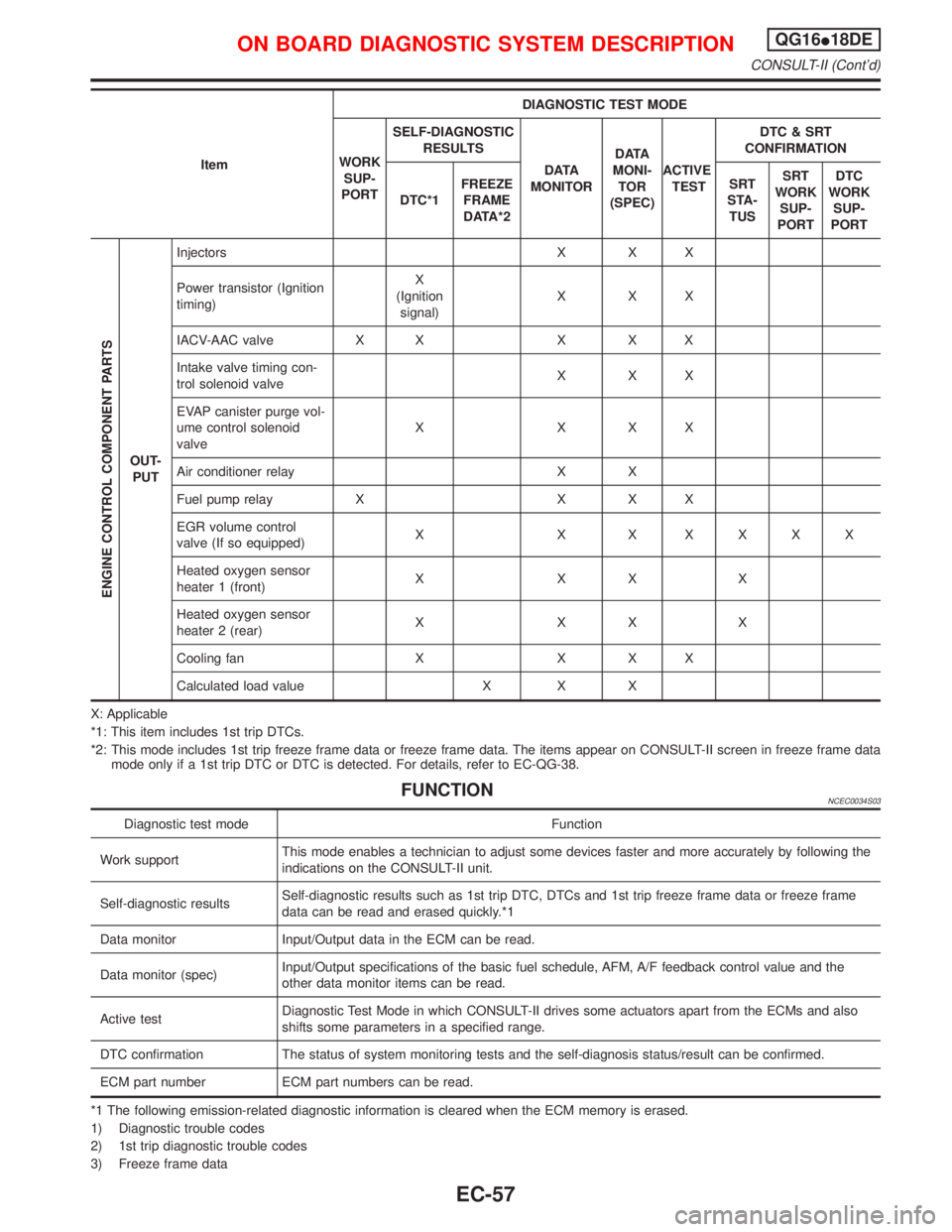
ItemDIAGNOSTIC TEST MODE
WORK
SUP-
PORTSELF-DIAGNOSTIC
RESULTS
D ATA
MONITORD ATA
MONI-
TOR
(SPEC)ACTIVE
TESTDTC & SRT
CONFIRMATION
DTC*1FREEZE
FRAME
DATA*2SRT
STA-
TUSSRT
WORK
SUP-
PORTDTC
WORK
SUP-
PORT
ENGINE CONTROL COMPONENT PARTS
OUT-
PUTInjectors X X X
Power transistor (Ignition
timing)X
(Ignition
signal)XXX
IACV-AAC valve X X X X X
Intake valve timing con-
trol solenoid valveXXX
EVAP canister purge vol-
ume control solenoid
valveXXXX
Air conditioner relay X X
Fuel pump relay X X X X
EGR volume control
valve (If so equipped)X X X XXXX
Heated oxygen sensor
heater 1 (front)XXXX
Heated oxygen sensor
heater 2 (rear)XXXX
Cooling fan X X X X
Calculated load value X X X
X: Applicable
*1: This item includes 1st trip DTCs.
*2: This mode includes 1st trip freeze frame data or freeze frame data. The items appear on CONSULT-II screen in freeze frame data
mode only if a 1st trip DTC or DTC is detected. For details, refer to EC-QG-38.
FUNCTIONNCEC0034S03
Diagnostic test mode Function
Work supportThis mode enables a technician to adjust some devices faster and more accurately by following the
indications on the CONSULT-II unit.
Self-diagnostic resultsSelf-diagnostic results such as 1st trip DTC, DTCs and 1st trip freeze frame data or freeze frame
data can be read and erased quickly.*1
Data monitor Input/Output data in the ECM can be read.
Data monitor (spec)Input/Output specifications of the basic fuel schedule, AFM, A/F feedback control value and the
other data monitor items can be read.
Active testDiagnostic Test Mode in which CONSULT-II drives some actuators apart from the ECMs and also
shifts some parameters in a specified range.
DTC confirmation The status of system monitoring tests and the self-diagnosis status/result can be confirmed.
ECM part number ECM part numbers can be read.
*1 The following emission-related diagnostic information is cleared when the ECM memory is erased.
1) Diagnostic trouble codes
2) 1st trip diagnostic trouble codes
3) Freeze frame data
ON BOARD DIAGNOSTIC SYSTEM DESCRIPTIONQG16I18DE
CONSULT-II (Cont'd)
EC-57