Page 1551 of 2053
SSANGYONG MY2002
7C-22 MANUAL & SEMIAUTO-HVAC
3. Disconnect the inlet and outlet pipes of receiver
drier.
Notice: When installing, check the O-ring and
apply the compressor oil.
Installation Notice
4. Remove the bracket bolt and then remove the
receiver drier.
Installation Notice
5. Installation should follow the removal procedure
in the reverse order.
KAA7C250
Removal & Installation Procedure
1. Disconnect the negative(-) terminal from the
battery.
2. Discharge refrigerant from the system.
Notice: By connecting a manifold gauge
connection hose to High/Low pressure line,
discharge the refrigerant.
Tightening Torque4 - 6 Nm
(35 - 53 lb-in)
Tightening Torque5 - 8 Nm
(44 - 71 lb-in)
Page 1556 of 2053
SSANGYONG MY2002
7D-2 FATC-HAVC
SPECIFICATIONS
REFRIGERANT
Core Size (LxWxT)
Core Type
Expansion Valve Type
Thermostat
Resister Type
Cooling CapacityApplicationDescription237.0 x 232.0 x 92.0
Aluminum plate
Angle
ON:4.5 ± 0.6°C, OFF:1.5 ± 0.6°C
Aluminum plate
4,300 Kcal/h (AT 420 CMH)
Capacity
TypeApplicationDescription650 - 750 g
R134a
EVAPORATOR UNIT
BLOWER UNIT
Motor Type
Motor SizeApplicationDescriptionMagnetic
φ 70 x
145
COMPRESSOR
Model
Type
Displacement (cc/rev.)
PCD (Pulley Center Diameter)
Oil
Magnetic clutch outputApplicationDescriptionFK-II (DKV 14C)
Vane rotary type
140.5 (cc/rev)
φ 143
ZXL 200 PG (PAG Oil)
45 W
CONDENSER
Size (WxHxT)
Capacity
TypeApplicationDescription650 x 339.2 x 22.0
11,000 Kcal/h
Parallel Flow
RECEIVER DRIER
Material
Capacity
DesiccantApplicationDescriptionAluminum
250 cc
XH-9 (35 g)
Page 1590 of 2053

SUPPLEMENTAL RESTRAINTS SYSTEM 8B-5
SSANGYONG MY2002
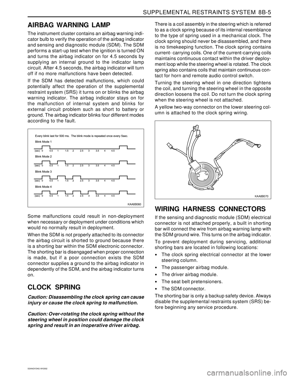
KAA8B060
AIRBAG WARNING LAMP
The instrument cluster contains an airbag warning indi-
cator bulb to verify the operation of the airbag indicator
and sensing and diagnostic module (SDM). The SDM
performs a start-up test when the ignition is turned ON
and turns the airbag indicator on for 4.5 seconds by
supplying an internal ground to the indicator lamp
circuit. After 4.5 seconds, the airbag indicator will turn
off if no more malfunctions have been detected.
If the SDM has detected malfunctions, which could
potentially affect the operation of the supplemental
restraint system (SRS) it turns on or blinks the airbag
warning indicator. The airbag indicator stays on for
the malfunction of internal system and blinks for
external circuit problem such as short to battery or
ground. The airbag indicator blinks four different modes
according to the fault.
Some malfunctions could result in non-deployment
when necessary or deployment under conditions which
would no normally result in deployment.
When the SDM is not properly attached to its connector
the airbag circuit is shorted to ground because there
is a shorting bar within the SDM electronic connector.
The shorting bar is disengaged when proper connection
is made, but if a poor connection exists the SDM
connector supplies a ground to the airbag indicator in
dependently of the SDM, and the airbag indicator turns
on.
CLOCK SPRING
Caution: Disassembling the clock spring can cause
injury or cause the clock spring to malfunction.
Caution: Over-rotating the clock spring without the
steering wheel in position could damage the clock
spring and result in an inoperative driver airbag.There is a coil assembly in the steering which is referred
to as a clock spring because of its internal resemblance
to the type of spring used in a mechanical clock. The
clock spring should never be disassembled, and there
is no timekeeping function. The clock spring contains
current- carrying coils. One of the current-carrying coils
maintains continuous contact within the driver deploy-
ment loop while the steering wheel is rotated. The clock
spring also contains coils that maintain continuous con-
tact for horn and remote audio control switch.
Turning the steering wheel in one direction tightens
the coil, and turning the steering wheel in the opposite
direction loosens the coil. Do not turn the clock spring
when the steering wheel is not attached.
A yellow two-way connector on the lower steering col-
umn is attached to the clock spring wiring.
WIRING HARNESS CONNECTORS
If the sensing and diagnostic module (SDM) electrical
connector is not attached properly, a built in shorting
bar will connect the wire from airbag warning lamp with
the SDM ground wire. This turns on the airbag indicator.
To prevent deployment during servicing, additional
shorting bars are located in following locations:
The clock spring electrical connector at the lower
steering column.
The passenger airbag module.
The driver airbag module.
The seat belt pretensioners.
The SDM connector.
The shorting bar is only a backup safety device. Always
disable the supplemental restraints system (SRS) be-
fore beginning any service procedure.
KAA8B070
Page 1664 of 2053

BODY WIRING SYSTEM 9A-13
SSANGYONG MY2002
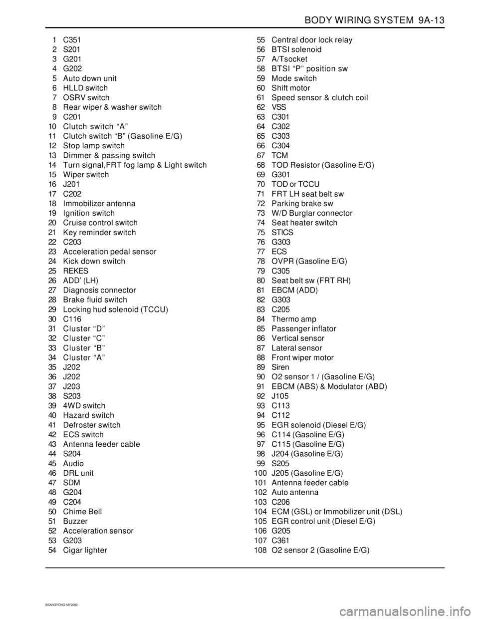
1 C351
2 S201
3 G201
4 G202
5 Auto down unit
6 HLLD switch
7 OSRV switch
8 Rear wiper & washer switch
9 C201
10 Clutch switch “A”
11 Clutch switch “B” (Gasoline E/G)
12 Stop lamp switch
13 Dimmer & passing switch
14 Turn signal,FRT fog lamp & Light switch
15 Wiper switch
16 J201
17 C202
18 Immobilizer antenna
19 Ignition switch
20 Cruise control switch
21 Key reminder switch
22 C203
23 Acceleration pedal sensor
24 Kick down switch
25 REKES
26 ADD’ (LH)
27 Diagnosis connector
28 Brake fluid switch
29 Locking hud solenoid (TCCU)
30 C116
31 Cluster “D”
32 Cluster “C”
33 Cluster “B”
34 Cluster “A”
35 J202
36 J202
37 J203
38 S203
39 4WD switch
40 Hazard switch
41 Defroster switch
42 ECS switch
43 Antenna feeder cable
44 S204
45 Audio
46 DRL unit
47 SDM
48 G204
49 C204
50 Chime Bell
51 Buzzer
52 Acceleration sensor
53 G203
54 Cigar lighter55 Central door lock relay
56 BTSI solenoid
57 A/Tsocket
58 BTSI “P” position sw
59 Mode switch
60 Shift motor
61 Speed sensor & clutch coil
62 VSS
63 C301
64 C302
65 C303
66 C304
67 TCM
68 TOD Resistor (Gasoline E/G)
69 G301
70 TOD or TCCU
71 FRT LH seat belt sw
72 Parking brake sw
73 W/D Burglar connector
74 Seat heater switch
75 STICS
76 G303
77 ECS
78 OVPR (Gasoline E/G)
79 C305
80 Seat belt sw (FRT RH)
81 EBCM (ADD)
82 G303
83 C205
84 Thermo amp
85 Passenger inflator
86 Vertical sensor
87 Lateral sensor
88 Front wiper motor
89 Siren
90 O2 sensor 1 / (Gasoline E/G)
91 EBCM (ABS) & Modulator (ABD)
92 J105
93 C113
94 C112
95 EGR solenoid (Diesel E/G)
96 C114 (Gasoline E/G)
97 C115 (Gasoline E/G)
98 J204 (Gasoline E/G)
99 S205
100 J205 (Gasoline E/G)
101 Antenna feeder cable
102 Auto antenna
103 C206
104 ECM (GSL) or Immobilizer unit (DSL)
105 EGR control unit (Diesel E/G)
106 G205
107 C361
108 O2 sensor 2 (Gasoline E/G)
Page 1671 of 2053
SSANGYONG MY2002
9A-20 BODY WIRING SYSTEM
W/H ENGINE CONTROL (GASOLINE)
6 Crankshaft position sensor
7 Oil pressure switch
8 Knock sensor 2
9 Air flow sensor
10 Ignition coil 3
11 Ignition coil 2
12 Ignition coil 1
13 Injector 6
14 Injector 5
15 Injector 416 Injector 3
17 Injector 2
18 Injector 1
19 Camshaft actuator
20 Camshaft position sensor
21 Engine coolant temperature sensor (Gauge)
22 Engine temperature sensor
23 Throttle motor & sensor
24 Knock sensor 1
25 Intake manifold resonance flap
KAA9A150
Page 1673 of 2053
SSANGYONG MY2002
9A-22 BODY WIRING SYSTEM
W/H TRANSMISSION
Automatic Transmission
3 Transmission
4 T/M Lever
5 Inhibitor switch
6 Micro switch (Diesel E/G)7 Throttle position sensor (Diesel E/G)
8 Engine oil pressure switch
9 Engine speed sensor (Diesel E/G)
YAD9B350
Page 1674 of 2053
BODY WIRING SYSTEM 9A-23
SSANGYONG MY2002
Manual Transmission
1 C302
2 Back up switch
3 Micro switch4 Engine oil pressure switch
5 Engine speed sensor
YAD9B350
Page 1781 of 2053

SQUEAKS AND RATTLES 9K-3
SSANGYONG MY2002
Check for a lack of lubrication of the door hinge pins.ChecksActionOperate the doors and listen for squeaks.
Lubricate the door hinge pins with light oil and coat
with lithium grease.
Squeak Coming From Console When Shifting Manual Transaxle
(Condition Occurs In Cold Weather with a Cold Engine)
Check the manual transaxle control lever lower boot.ChecksActionMove the control lever between gears and listen for
squeaks.
Remove the floor console and replace the lower shift
boot or apply talcum powder to the lower shift boot.
Squeak When Operating Doors
Check for vibration of the fuse box cover against the
instrument panel side trim.ChecksActionTap on thecoverwith a fingerandlisten fora buzz.
Apply 6.35 mm (0.250 inch) by 25.4 mm (1.00 inch)
felt pads to the side trim where the cover makes
contact.
Squeak Coming From Instrument Cluster Trim Plate
Check for rubbing of the cluster trim plate on the
instrument panel.ChecksActionTest drive the vehicle in order to verify this condi-
tion.
Remove the instrument cluster trim plate and install
felt tape to the edges.
Buzz From the Left Side of Instrument Panel
Check the door lock solenoid.
Check for rattling electrical connectors inside the door
trim panel.ChecksActionRemove the door trim panel and check if the sole-
noid is loose.
Tighten the solenoid bolts.
Tap on the trim panel and listen for a rattle.
Remove the trim panel and wrap foam padding
around the connectors as required.
Rattle Coming From Door