1997 SSANGYONG KORANDO center console
[x] Cancel search: center consolePage 1097 of 2053
AUTOMATIC TRANSMISSION 5A-3
SSANGYONG MY2002
N - Neutral allows the engine to be started and oper-
ated while driving the vehicle. The inhibitor switch
allows the engine to be started. There is no power
transferred through the transmission in Neutral. But
the final drive is not locked by the parking pawl, so
thewheels are free to rotate.
D - Overdrive range is used for all normal driving
conditions. 4th gear (overdrive gear) reduces the
fuel consumption and the engine noise. Engine
braking is applied with reduced throttle.
First to second (1 → 2), first to third (1 → 3), second
to third (2 → 3), second to fourth (2 → 4), third to
fourth (3 → 4), fourth to third (4 → 3), fourth to
second (4 → 2), third to second (3 → 2), third to
first (3 → 1) and second to first (2 → 1) shifts are
all available as a function of vehicle speed, throttle
position and the time change rate of the throttle
position.
Downshifts are available for safe passing by
depress-ing the accelerator. Lockup clutch may be
enabled in 3rd and 4th gears depending on vehicle
type.
3 - Manual 3 provides three gear ratios (first through
third) and prevents the transmission from operating
in 4th gear. 3rd gear is used when driving on long
hill roads or in heavy city traffic. Downshifts are
available by depressing the accelerator.
2 - Manual 2 provides two gear ratios (first and
second). It is used to provide more power when
climbing hills or engine braking when driving down
a steep hill or starting off on slippery roads.
1 - Manual 1 is used to provide the maximum engine
braking when driving down the severe gradients.When NORMAL mode is selected upshifts will occur
to maximize fuel economy. When POWER mode is se-
lected, upshifts will occur to give maximum
performance and the POWER mode indicator light is
switched ON.
When WINTER mode is selected, starting in second
gear is facilitated, the WINTER mode indicator light is
switched ON and the POWER mode indicator light is
switched OFF.
Indicator Light
The indicator light is located on the instrument panel.
Auto shift indicator light comes ON when the ignition
switch ON and shows the gear shift control lever
position.
POWER mode indicator light comes ON when the
POWER mode is selected and when the kickdown
switch is depressed.
WINTER mode indicator light comes ON when the
WINTER mode is selected.
CONTROL SYSTEMS
BTRA M74 4WD automatic transmission consists of
two control systems. One is the electronic control
system that monitors vehicle parameters and adjusts
the transmission performance. Another is the hydraulic
control system that implements the commands of the
electronic control system commands.
ELECTRONIC CONTROL SYSTEM
The electronic control system comprises of sensors, a
TCM and seven solenoids. The TCM reads the inputs
and activates the outputs according to values stored
in Read Only Memory (ROM).
The TCM controls the hydraulic control system. This
control is via the hydraulic valve body, which contains
seven electromagnetic solenoids. Six of the seven
solenoids are used to control the line pressure, operate
the shift valves and the torque converter lock-up clutch,
and to turn ON and OFF the two regulator valves that
control the shift feel.
The seventh solenoid is the proportional or Variable
Pressure Solenoid (VPS) which works with the two regu-
lator valves to control shift feel.
Transmission Control Module (TCM)
The TCM is an in-vehicle micro-processor based trans-
mission management system. It is mounted under the
driver’s side front seat in the vehicle cabin.
The TCM contains:
Processing logic circuits which include a central mi-
croprocessor controller and a back-up memory
system.
Input circuits.
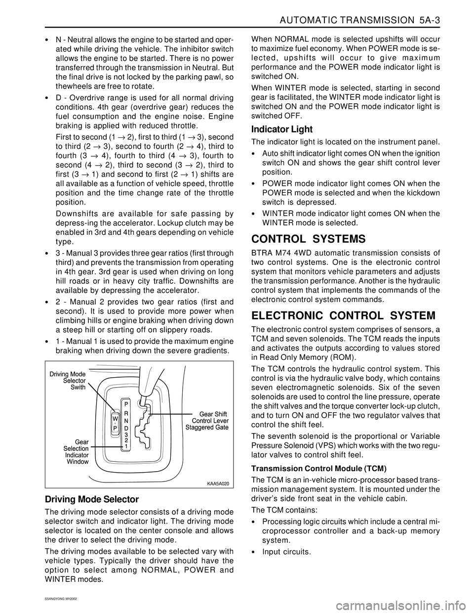
Driving Mode Selector
The driving mode selector consists of a driving mode
selector switch and indicator light. The driving mode
selector is located on the center console and allows
the driver to select the driving mode.
The driving modes available to be selected vary with
vehicle types. Typically the driver should have the
option to select among NORMAL, POWER and
WINTER modes.
KAA5A020
Page 1161 of 2053
5A-66 AUTOMATIC TRANSMISSION
SSANGYONG MY2002
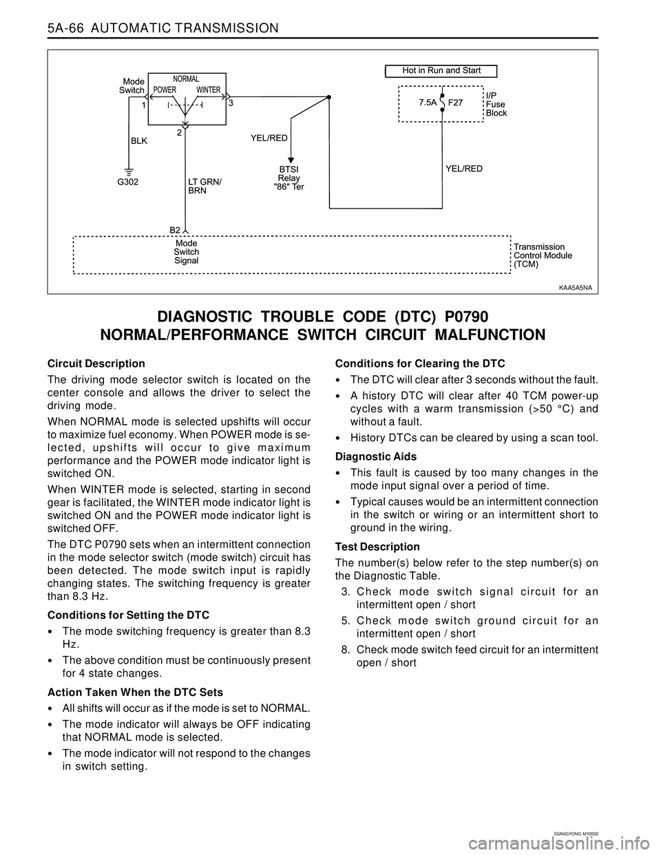
Circuit Description
The driving mode selector switch is located on the
center console and allows the driver to select the
driving mode.
When NORMAL mode is selected upshifts will occur
to maximize fuel economy. When POWER mode is se-
lected, upshifts will occur to give maximum
performance and the POWER mode indicator light is
switched ON.
When WINTER mode is selected, starting in second
gear is facilitated, the WINTER mode indicator light is
switched ON and the POWER mode indicator light is
switched OFF.
The DTC P0790 sets when an intermittent connection
in the mode selector switch (mode switch) circuit has
been detected. The mode switch input is rapidly
changing states. The switching frequency is greater
than 8.3 Hz.
Conditions for Setting the DTC
The mode switching frequency is greater than 8.3
Hz.
The above condition must be continuously present
for 4 state changes.
Action Taken When the DTC Sets
All shifts will occur as if the mode is set to NORMAL.
The mode indicator will always be OFF indicating
that NORMAL mode is selected.
The mode indicator will not respond to the changes
in switch setting.
DIAGNOSTIC TROUBLE CODE (DTC) P0790
NORMAL/PERFORMANCE SWITCH CIRCUIT MALFUNCTION
Conditions for Clearing the DTC
The DTC will clear after 3 seconds without the fault.
A history DTC will clear after 40 TCM power-up
cycles with a warm transmission (>50 °C) and
without a fault.
History DTCs can be cleared by using a scan tool.
Diagnostic Aids
This fault is caused by too many changes in the
mode input signal over a period of time.
Typical causes would be an intermittent connection
in the switch or wiring or an intermittent short to
ground in the wiring.
Test Description
The number(s) below refer to the step number(s) on
the Diagnostic Table.
3. Check mode switch signal circuit for an
intermittent open / short
5. Check mode switch ground circuit for an
intermittent open / short
8. Check mode switch feed circuit for an intermittent
open / short
KAA5A5NA
Page 1719 of 2053

SSANGYONG MY2002
9E-2 INSTRUMENTATION, DRIVER INFORMATION
DESCRIPTION AND OPERATION
CIGAR LIGHTER
The cigar lighter is located in the front portion of the
floor console. To use the lighter, push it in completely.
When the lighter is hot, it will release itsef from contact
with the heating element. The lighter and the heating
element can be damaged if the lighter does not fully
release itsef from the heating element.
ASHTRAY
The ashtray is located in the console. To access the
ashtray, pullit out of the ashtray housing. The ashtray
lamp will go on when the parking lamps or headlamps
are turned on.
INSTRUMENT PANEL VENTS
The center and the side vents in the instrument panel
can be adjusted up and down and from side to side.
The side vents can also be aimed toward the side
windows to defog them.
GLOVE BOX
The glove box can be opened by pulling upon the latch
handle.
DIGITAL CLOCK
The digital clock is located in the instrument cluster.
INSTRUMENT CLUSTER
The instrument cluster is located above the steering
column and in the instrument cluster trim panel. The
instrument cluster contains the instruments that
provide the driver with vehicle performance information.
The instrument cluster contains a speedometer, a
tachometer, an odometer, a trip odometer, a
temperature gauge, a fuel gauge, and several indicator
lamps. For replacement of the indicator lamp bulbs
contained in the instrument cluster, refer to “Instrument
Cluster Indicator Lamps Specifications” in the section.
SPEEDOMETER AND
TACHOMETER
The speedometer measures the speed of the vehicle
in km/h (with mph) or mph (with km/h). It consists of
an instrument cluster gauge connected to the vehicle
speed sensor on the transaxle output shaft. The
tachometer measures the engine’s speed in terms of
thousands of revolutions per minute. It consists of an
instrument cluster gauge connected to a sending unit
in the engine con-trol module. Do not operate the
engine in the red zone. Engine damage may occur.
TRIP ODOMETER
The trip odometer measures the distance the vehicle
has traveled since it was last reset. It consists of an
instrument cluster gauge connected to the sending unit
on the tasnsaxle output shaft. The trip oddometer can
be record the distance traveled from any starting point.
FUEL GAUGE
The fuel gauge consists of an instrument cluster gauge
connected to a sending unit in the fuel tank. The fuel
gauge indicates the quantity of fuel in the tank only
when the ignition is turned to ON or ACC. When the
ignition is turned to LOCK or START, the pointer may
come to rest at any position.
TEMPERATURE GAUGE
The temperature gauge consists of an instrument
cluster gauge connected to a temperature sensor that
is in con-tact with the circulating engine coolant. The
temperature gauge indicates the temperature of the
coolant. Prolonged driving or idling in very hot weather
may cause the pointer to move beyond the center of
the gauge. The engine is overheating if the pointer
moves into the red zone at the upper limit of the gauge.
INSTRUMENT CLUSTER
INDICATOR LAMPS
The instrument cluster contains indicator lamps that
indicatethe functioning of certain systems or the
existenceof potential problems with the operation of
the vehicle. The indicator lamps are replaceable. For
replacement of the indicator lamps contained in the
instrument cluster, refer to “instrument cluster indicator
lamps specifications” in this section.
CHIME MODULE
The chime module will sound to bring attention to one
or more of the following conditions:
The lights are on and the ignition not in ACC, ON,
or START.
The ignition key is in the ignition switch when the
driver’s side door is open.
The seat belt is unbuckled when the ignition is in
ACC, ON, or START.
Voltage is supplied at all times through the fuse block
to power the chime module.
Page 1727 of 2053
SSANGYONG MY2002
9E-10 INSTRUMENTATION, DRIVER INFORMATION
COOL
HOT
KAA9E030
KAA9E040
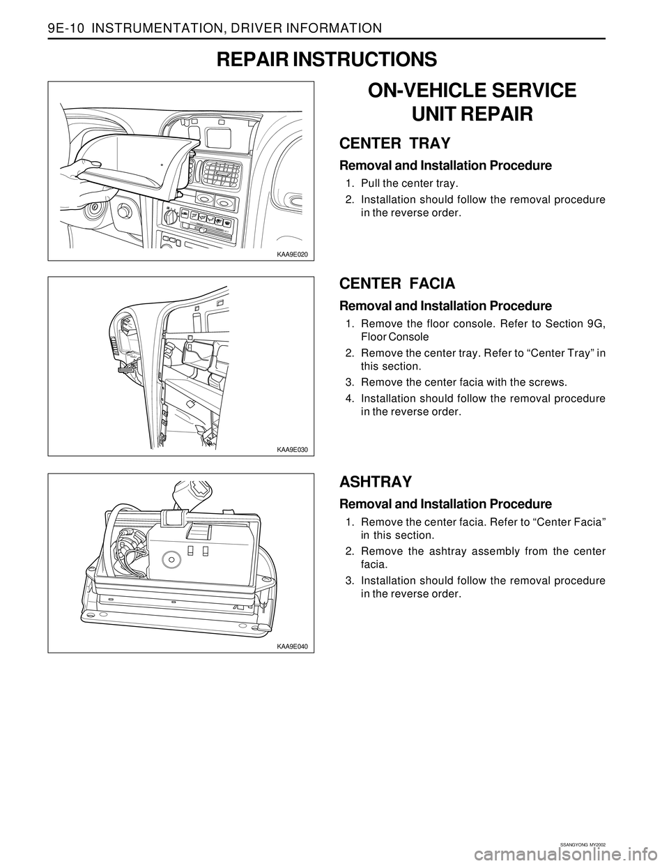
CENTER FACIA
Removal and Installation Procedure
1. Remove the floor console. Refer to Section 9G,
Floor Console
2. Remove the center tray. Refer to “Center Tray” in
this section.
3. Remove the center facia with the screws.
4. Installation should follow the removal procedure
in the reverse order.
ASHTRAY
Removal and Installation Procedure
1. Remove the center facia. Refer to “Center Facia”
in this section.
2. Remove the ashtray assembly from the center
facia.
3. Installation should follow the removal procedure
in the reverse order.
KAA9E020
ON-VEHICLE SERVICE
UNIT REPAIR
CENTER TRAY
Removal and Installation Procedure
1. Pull the center tray.
2. Installation should follow the removal procedure
in the reverse order.
REPAIR INSTRUCTIONS
Page 1728 of 2053
INSTRUMENTATION, DRIVER INFORMATION 9E-11
SSANGYONG MY2002
KAA9E060
KAA9E070
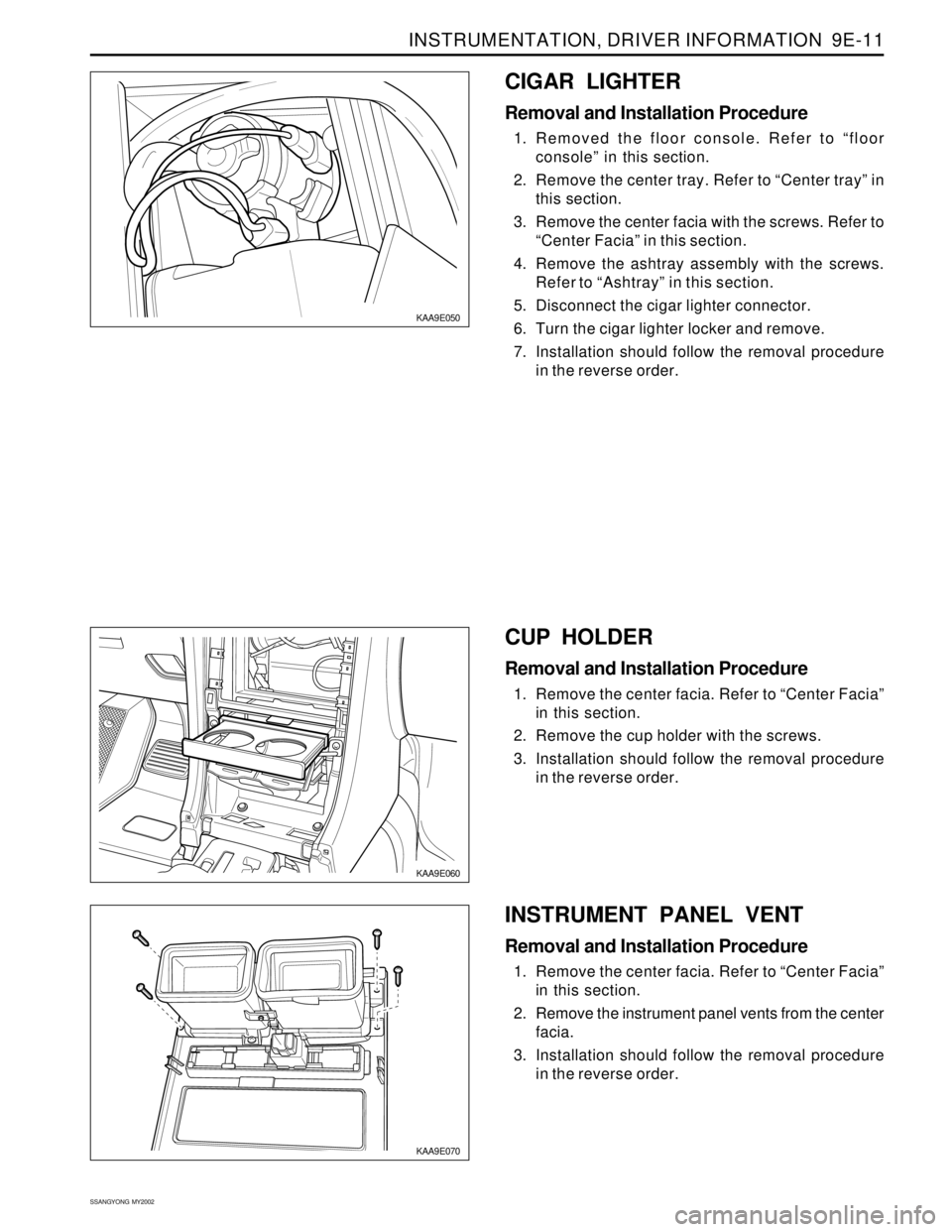
CUP HOLDER
Removal and Installation Procedure
1. Remove the center facia. Refer to “Center Facia”
in this section.
2. Remove the cup holder with the screws.
3. Installation should follow the removal procedure
in the reverse order.
KAA9E050
CIGAR LIGHTER
Removal and Installation Procedure
1. Removed the floor console. Refer to “floor
console” in this section.
2. Remove the center tray. Refer to “Center tray” in
this section.
3. Remove the center facia with the screws. Refer to
“Center Facia” in this section.
4. Remove the ashtray assembly with the screws.
Refer to “Ashtray” in this section.
5. Disconnect the cigar lighter connector.
6. Turn the cigar lighter locker and remove.
7. Installation should follow the removal procedure
in the reverse order.
INSTRUMENT PANEL VENT
Removal and Installation Procedure
1. Remove the center facia. Refer to “Center Facia”
in this section.
2. Remove the instrument panel vents from the center
facia.
3. Installation should follow the removal procedure
in the reverse order.
Page 1733 of 2053
SSANGYONG MY2002
9E-16 INSTRUMENTATION, DRIVER INFORMATION
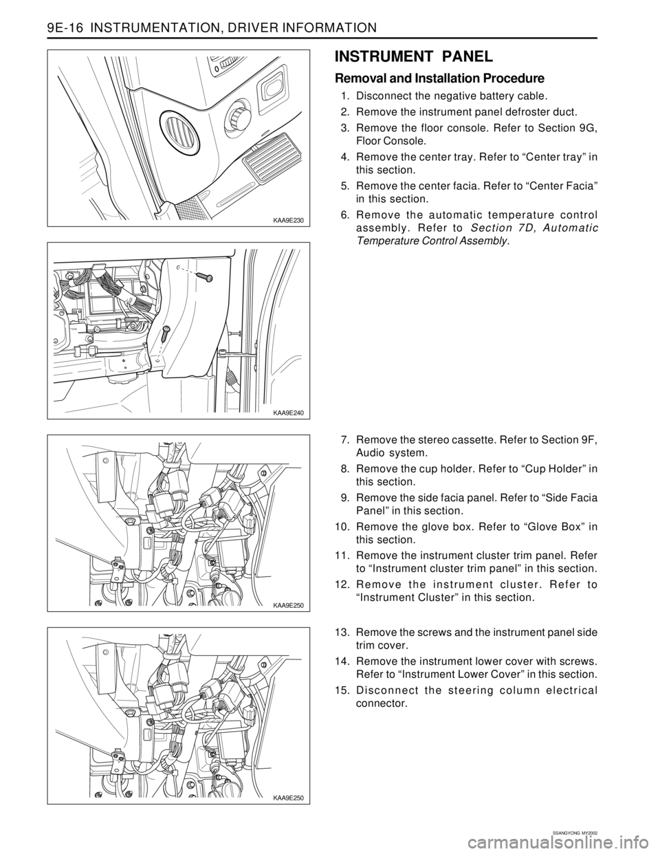
KAA9E250
KAA9E250
7. Remove the stereo cassette. Refer to Section 9F,
Audio system.
8. Remove the cup holder. Refer to “Cup Holder” in
this section.
9. Remove the side facia panel. Refer to “Side Facia
Panel” in this section.
10. Remove the glove box. Refer to “Glove Box” in
this section.
11. Remove the instrument cluster trim panel. Refer
to “Instrument cluster trim panel” in this section.
12. Remove the instrument cluster. Refer to
“Instrument Cluster” in this section.
13. Remove the screws and the instrument panel side
trim cover.
14. Remove the instrument lower cover with screws.
Refer to “Instrument Lower Cover” in this section.
15. Disconnect the steering column electrical
connector.
KAA9E240
INSTRUMENT PANEL
Removal and Installation Procedure
1. Disconnect the negative battery cable.
2. Remove the instrument panel defroster duct.
3. Remove the floor console. Refer to Section 9G,
Floor Console.
4. Remove the center tray. Refer to “Center tray” in
this section.
5. Remove the center facia. Refer to “Center Facia”
in this section.
6. Remove the automatic temperature control
assembly. Refer to Section 7D, Automatic
Temperature Control Assembly.
KAA9E230
Page 1751 of 2053
SSANGYONG MY2002
9G-2 INTERIOR TRIM
DESCRIPTION AND OPERATION
INTERIOR TRIM PANELS
The interior trim panels are molded plastic and fasten
with screws or plastic clips.
FLOOR CARPET
The floor carpets are divided front and rear floor carpet.
FLOOR CONSOLE
The floor console fits over the tunnel in the floor of the
vehicle and extends from under the center of the
instrument panel to the rear seat area. The floor console
contains the transaxle shift lever, parking brake lever,
a storage compartment and coin storage
Page 1809 of 2053
FRAME AND UNDERBODY 9N-7
SSANGYONG MY2002
ON-VEHICLE SERVICE
ALIGNMENT CHECKING
An accurate method of determining the alignment of
the underbody uses a measuring tram gauge. The tram
gauge set used to perform the recommended
measuring checks must include a vertical pointer able
to reach 457 mm (18 inches).
Two types of measurements can be made with a tram
gauge: direct point-to-point measurements and
measurements calculated on a horizontal plane (datum
line) parallel to the underbody. Point-to-point
measurements are generally taken on steering and
suspension engine compartment parts and simply
require the vertical pointers to be set equally.
For horizontal plane measurements, the vertical pointers
must be set as specified for each point to be measured.
Dimensions-to-gauge holes are measured to the center
of the holes and flush to the adjacent surface metal
unless otherwise specified. It is recommended that
the diagonal dimensions to the cross-body be checked
on both sides in order to verify the dimensional
accuracy of the vehicle underbody.
FLOOR PAN INSULATORS
The floor pan insulators have been designed for the
higher floor pan temperatures that result from the use
of the catalytic converter in the exhaust system.
Therefore, when servicing a vehicle, it is essential that
any insulators that may have been disturbed or removed
be reinstalled in the original sequence and location.
Also, if an insulator needs to be replaced, use only
the insula-tion specified for that location on the floor
pan.
When servicing or replacing interior insulators, observe
the following instructions.
•Install the insulators in the original position and
sequence. Butt the pieces together in order to
avoid gapping or overlapping.
If it is necessary to replace an insulator, use only
the specified insulation.
Use the original part to determine the amount of
re-placement material required and as a template
for cutting and fitting the new piece to the floor
pan.
When installing the insulator, do not enlarge any
cut-outs or holes that are used for the attachment
of interior parts such as the instrument panel or
the floor console.
MAINTENANCE AND REPAIR