1997 SSANGYONG KORANDO audio
[x] Cancel search: audioPage 1085 of 2053
SSANGYONG MY2002
4F-102 ABS AND TCS
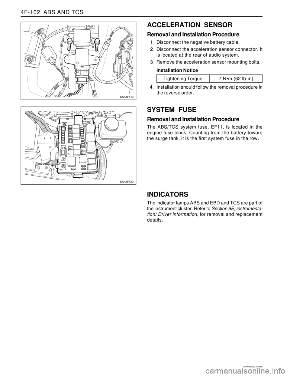
ACCELERATION SENSOR
Removal and Installation Procedure
1. Disconnect the negative battery cable.
2. Disconnect the acceleration sensor connector. It
is located at the rear of audio system.
3. Remove the acceleration sensor mounting bolts.
Installation Notice
SYSTEM FUSE
Removal and Installation Procedure
The ABS/TCS system fuse, EF11, is located in the
engine fuse block. Counting from the battery toward
the surge tank, it is the first system fuse in the row.
KAA4F410
KAA4F420
Tightening Torque 7 Nm (62 lb-in)
4. Installation should follow the removal procedure in
the reverse order.
INDICATORS
The indicator lamps ABS and EBD and TCS are part of
the instrument cluster. Refer to Section 9E, instrumenta-
tion/ Driver information, for removal and replacement
details.
Page 1569 of 2053
FATC-HAVC 7D-15
SSANGYONG MY2002
EF
80100460810
KAA7D090
KAA7D100
KAA7D110
KAA7D120
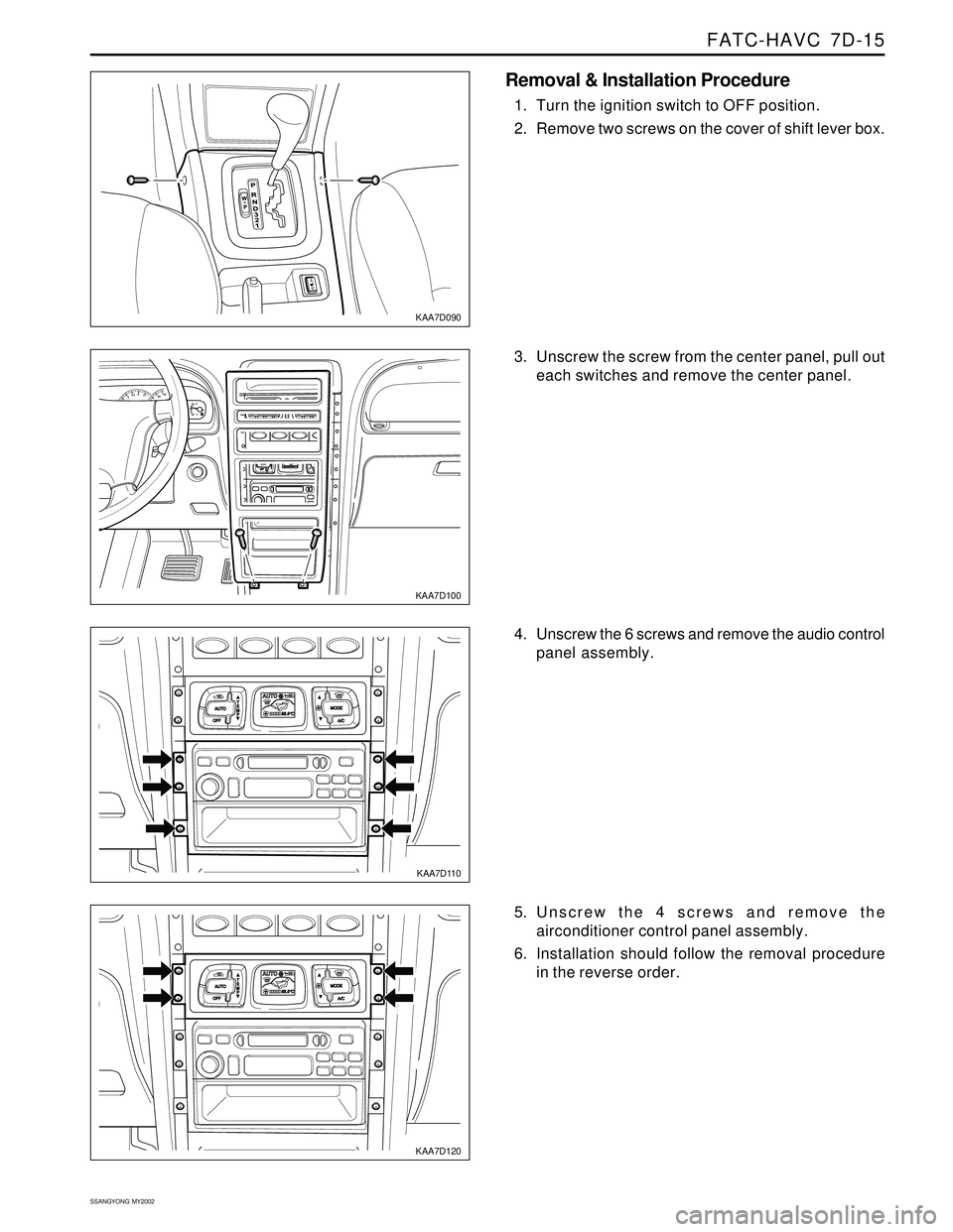
Removal & Installation Procedure
1. Turn the ignition switch to OFF position.
2. Remove two screws on the cover of shift lever box.
3. Unscrew the screw from the center panel, pull out
each switches and remove the center panel.
4. Unscrew the 6 screws and remove the audio control
panel assembly.
5. Unscrew the 4 screws and remove the
airconditioner control panel assembly.
6. Installation should follow the removal procedure
in the reverse order.
Page 1590 of 2053
SUPPLEMENTAL RESTRAINTS SYSTEM 8B-5
SSANGYONG MY2002
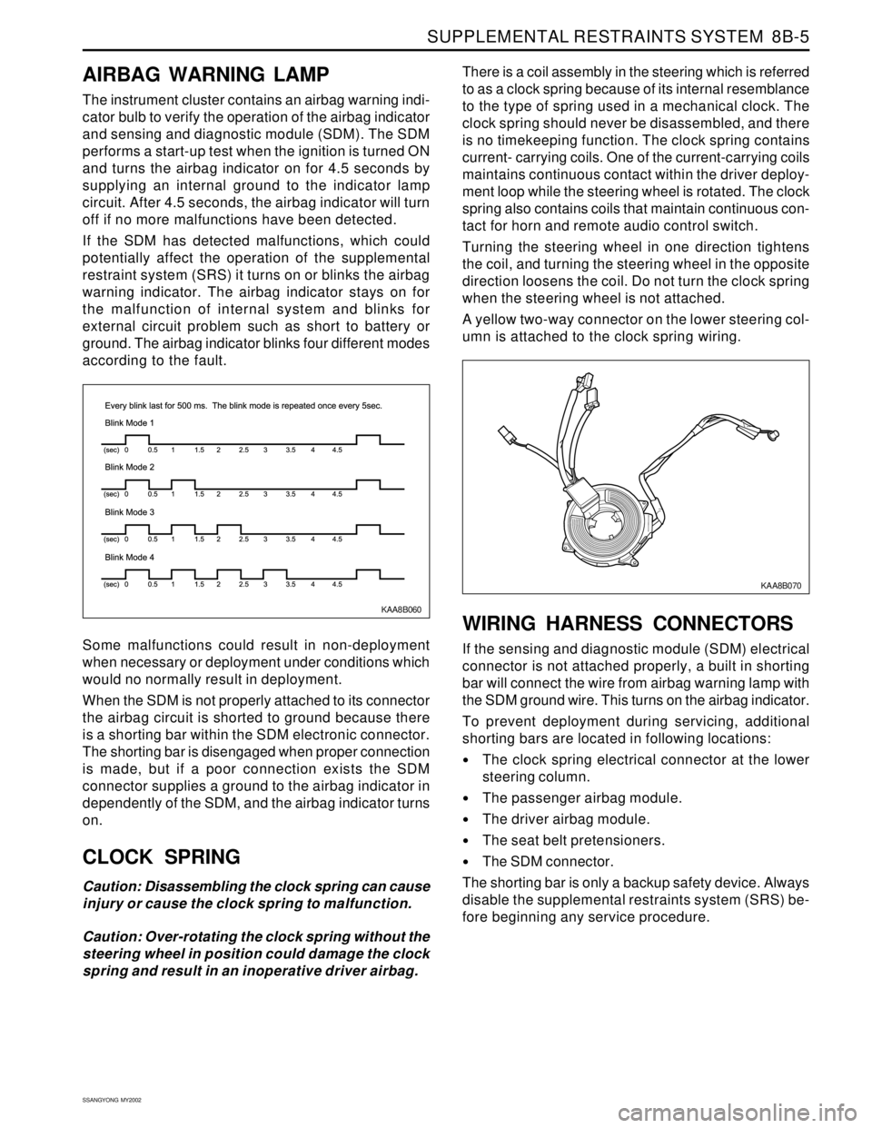
KAA8B060
AIRBAG WARNING LAMP
The instrument cluster contains an airbag warning indi-
cator bulb to verify the operation of the airbag indicator
and sensing and diagnostic module (SDM). The SDM
performs a start-up test when the ignition is turned ON
and turns the airbag indicator on for 4.5 seconds by
supplying an internal ground to the indicator lamp
circuit. After 4.5 seconds, the airbag indicator will turn
off if no more malfunctions have been detected.
If the SDM has detected malfunctions, which could
potentially affect the operation of the supplemental
restraint system (SRS) it turns on or blinks the airbag
warning indicator. The airbag indicator stays on for
the malfunction of internal system and blinks for
external circuit problem such as short to battery or
ground. The airbag indicator blinks four different modes
according to the fault.
Some malfunctions could result in non-deployment
when necessary or deployment under conditions which
would no normally result in deployment.
When the SDM is not properly attached to its connector
the airbag circuit is shorted to ground because there
is a shorting bar within the SDM electronic connector.
The shorting bar is disengaged when proper connection
is made, but if a poor connection exists the SDM
connector supplies a ground to the airbag indicator in
dependently of the SDM, and the airbag indicator turns
on.
CLOCK SPRING
Caution: Disassembling the clock spring can cause
injury or cause the clock spring to malfunction.
Caution: Over-rotating the clock spring without the
steering wheel in position could damage the clock
spring and result in an inoperative driver airbag.There is a coil assembly in the steering which is referred
to as a clock spring because of its internal resemblance
to the type of spring used in a mechanical clock. The
clock spring should never be disassembled, and there
is no timekeeping function. The clock spring contains
current- carrying coils. One of the current-carrying coils
maintains continuous contact within the driver deploy-
ment loop while the steering wheel is rotated. The clock
spring also contains coils that maintain continuous con-
tact for horn and remote audio control switch.
Turning the steering wheel in one direction tightens
the coil, and turning the steering wheel in the opposite
direction loosens the coil. Do not turn the clock spring
when the steering wheel is not attached.
A yellow two-way connector on the lower steering col-
umn is attached to the clock spring wiring.
WIRING HARNESS CONNECTORS
If the sensing and diagnostic module (SDM) electrical
connector is not attached properly, a built in shorting
bar will connect the wire from airbag warning lamp with
the SDM ground wire. This turns on the airbag indicator.
To prevent deployment during servicing, additional
shorting bars are located in following locations:
The clock spring electrical connector at the lower
steering column.
The passenger airbag module.
The driver airbag module.
The seat belt pretensioners.
The SDM connector.
The shorting bar is only a backup safety device. Always
disable the supplemental restraints system (SRS) be-
fore beginning any service procedure.
KAA8B070
Page 1643 of 2053
SUPPLEMENTAL RESTRAINTS SYSTEM 8B-61
SSANGYONG MY2002
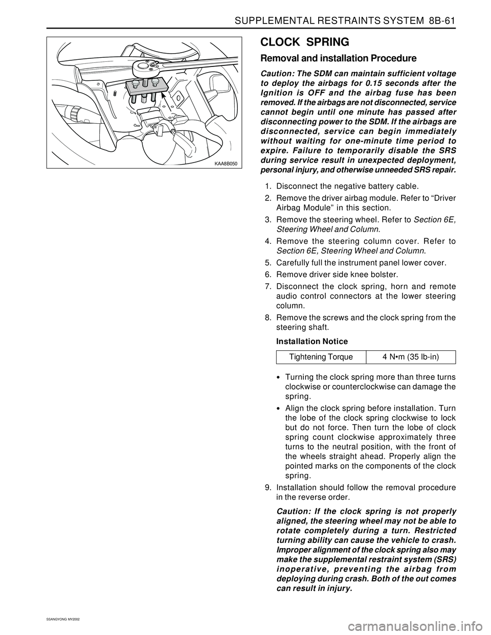
KAA8B050
CLOCK SPRING
Removal and installation Procedure
Caution: The SDM can maintain sufficient voltage
to deploy the airbags for 0.15 seconds after the
Ignition is OFF and the airbag fuse has been
removed. If the airbags are not disconnected, service
cannot begin until one minute has passed after
disconnecting power to the SDM. If the airbags are
disconnected, service can begin immediately
without waiting for one-minute time period to
expire. Failure to temporarily disable the SRS
during service result in unexpected deployment,
personal injury, and otherwise unneeded SRS repair.
1. Disconnect the negative battery cable.
2. Remove the driver airbag module. Refer to “Driver
Airbag Module” in this section.
3. Remove the steering wheel. Refer to Section 6E,
Steering Wheel and Column.
4. Remove the steering column cover. Refer to
Section 6E, Steering Wheel and Column.
5. Carefully full the instrument panel lower cover.
6. Remove driver side knee bolster.
7. Disconnect the clock spring, horn and remote
audio control connectors at the lower steering
column.
8. Remove the screws and the clock spring from the
steering shaft.
Installation Notice
Turning the clock spring more than three turns
clockwise or counterclockwise can damage the
spring.
Align the clock spring before installation. Turn
the lobe of the clock spring clockwise to lock
but do not force. Then turn the lobe of clock
spring count clockwise approximately three
turns to the neutral position, with the front of
the wheels straight ahead. Properly align the
pointed marks on the components of the clock
spring.
9. Installation should follow the removal procedure
in the reverse order.
Caution: If the clock spring is not properly
aligned, the steering wheel may not be able to
rotate completely during a turn. Restricted
turning ability can cause the vehicle to crash.
Improper alignment of the clock spring also may
make the supplemental restraint system (SRS)
inoperative, preventing the airbag from
deploying during crash. Both of the out comes
can result in injury.
Tightening Torque 4 Nm (35 lb-in)
Page 1658 of 2053
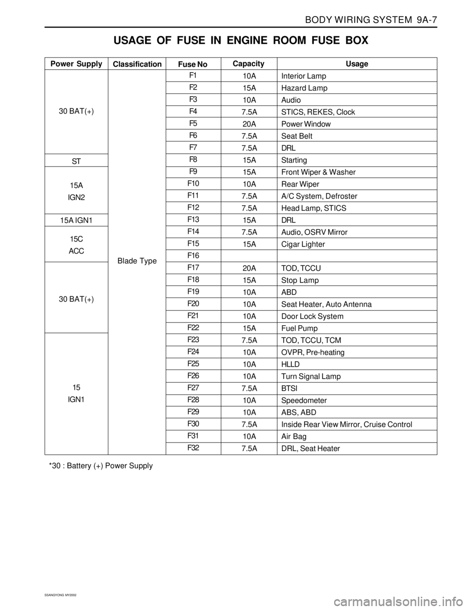
BODY WIRING SYSTEM 9A-7
SSANGYONG MY2002
USAGE OF FUSE IN ENGINE ROOM FUSE BOX
Interior Lamp
Hazard Lamp
Audio
STICS, REKES, Clock
Power Window
Seat Belt
DRL
Starting
Front Wiper & Washer
Rear Wiper
A/C System, Defroster
Head Lamp, STICS
DRL
Audio, OSRV Mirror
Cigar Lighter
TOD, TCCU
Stop Lamp
ABD
Seat Heater, Auto Antenna
Door Lock System
Fuel Pump
TOD, TCCU, TCM
OVPR, Pre-heating
HLLD
Turn Signal Lamp
BTSI
Speedometer
ABS, ABD
Inside Rear View Mirror, Cruise Control
Air Bag
DRL, Seat Heater Power SupplyUsage
Classification
Fuse NoCapacity
30 BAT(+)
ST
15A
IGN2
15A IGN1
15C
ACC
30 BAT(+)
15
IGN1
Blade TypeF1
F2
F3
F4
F5
F6
F7
F8
F9
F10
F11
F12
F13
F14
F15
F16
F17
F18
F19
F20
F21
F22
F23
F24
F25
F26
F27
F28
F29
F30
F31
F3210A
15A
10A
7.5A
20A
7.5A
7.5A
15A
15A
10A
7.5A
7.5A
15A
7.5A
15A
20A
15A
10A
10A
10A
15A
7.5A
10A
10A
10A
7.5A
10A
10A
7.5A
10A
7.5A
*30 : Battery (+) Power Supply
Page 1664 of 2053
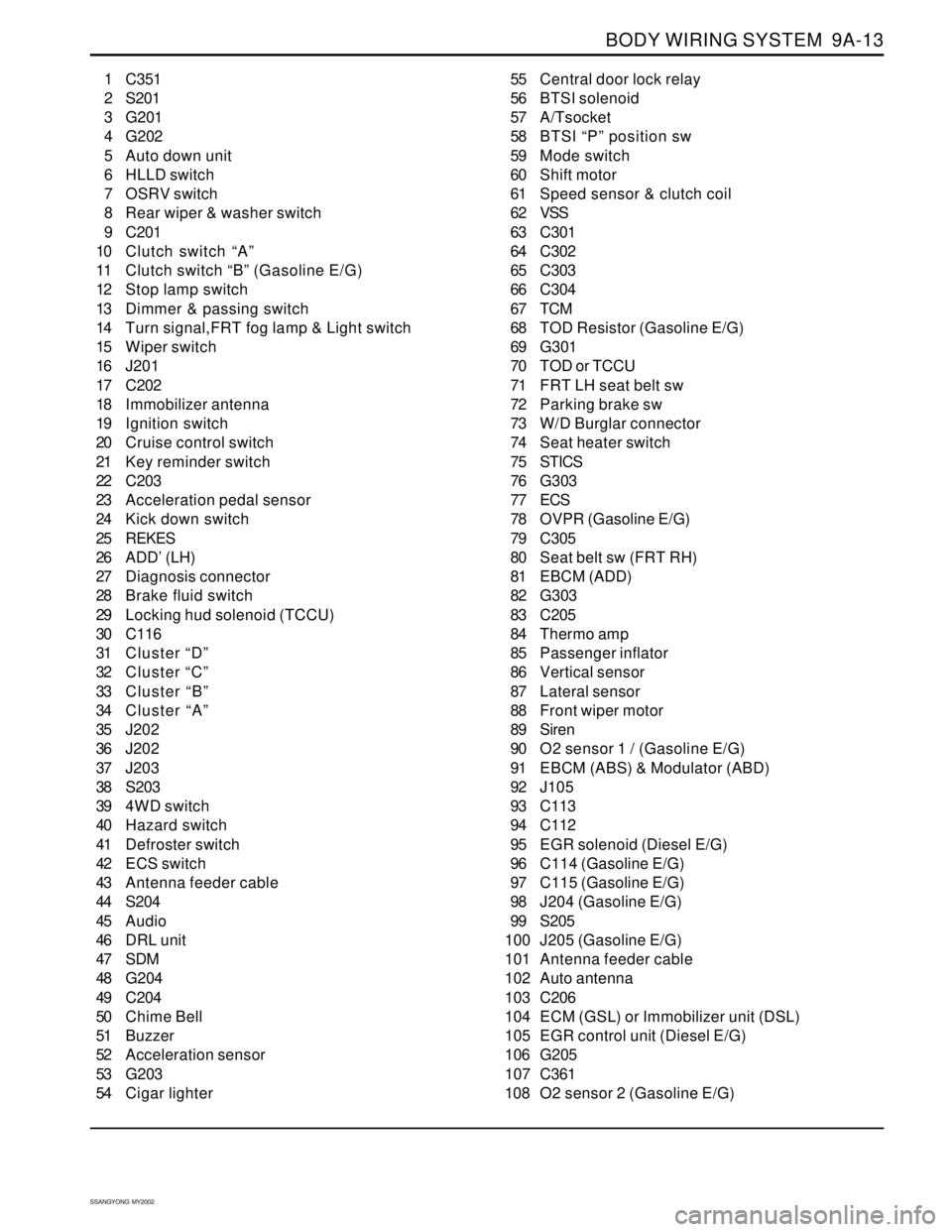
BODY WIRING SYSTEM 9A-13
SSANGYONG MY2002
1 C351
2 S201
3 G201
4 G202
5 Auto down unit
6 HLLD switch
7 OSRV switch
8 Rear wiper & washer switch
9 C201
10 Clutch switch “A”
11 Clutch switch “B” (Gasoline E/G)
12 Stop lamp switch
13 Dimmer & passing switch
14 Turn signal,FRT fog lamp & Light switch
15 Wiper switch
16 J201
17 C202
18 Immobilizer antenna
19 Ignition switch
20 Cruise control switch
21 Key reminder switch
22 C203
23 Acceleration pedal sensor
24 Kick down switch
25 REKES
26 ADD’ (LH)
27 Diagnosis connector
28 Brake fluid switch
29 Locking hud solenoid (TCCU)
30 C116
31 Cluster “D”
32 Cluster “C”
33 Cluster “B”
34 Cluster “A”
35 J202
36 J202
37 J203
38 S203
39 4WD switch
40 Hazard switch
41 Defroster switch
42 ECS switch
43 Antenna feeder cable
44 S204
45 Audio
46 DRL unit
47 SDM
48 G204
49 C204
50 Chime Bell
51 Buzzer
52 Acceleration sensor
53 G203
54 Cigar lighter55 Central door lock relay
56 BTSI solenoid
57 A/Tsocket
58 BTSI “P” position sw
59 Mode switch
60 Shift motor
61 Speed sensor & clutch coil
62 VSS
63 C301
64 C302
65 C303
66 C304
67 TCM
68 TOD Resistor (Gasoline E/G)
69 G301
70 TOD or TCCU
71 FRT LH seat belt sw
72 Parking brake sw
73 W/D Burglar connector
74 Seat heater switch
75 STICS
76 G303
77 ECS
78 OVPR (Gasoline E/G)
79 C305
80 Seat belt sw (FRT RH)
81 EBCM (ADD)
82 G303
83 C205
84 Thermo amp
85 Passenger inflator
86 Vertical sensor
87 Lateral sensor
88 Front wiper motor
89 Siren
90 O2 sensor 1 / (Gasoline E/G)
91 EBCM (ABS) & Modulator (ABD)
92 J105
93 C113
94 C112
95 EGR solenoid (Diesel E/G)
96 C114 (Gasoline E/G)
97 C115 (Gasoline E/G)
98 J204 (Gasoline E/G)
99 S205
100 J205 (Gasoline E/G)
101 Antenna feeder cable
102 Auto antenna
103 C206
104 ECM (GSL) or Immobilizer unit (DSL)
105 EGR control unit (Diesel E/G)
106 G205
107 C361
108 O2 sensor 2 (Gasoline E/G)
Page 1733 of 2053
SSANGYONG MY2002
9E-16 INSTRUMENTATION, DRIVER INFORMATION
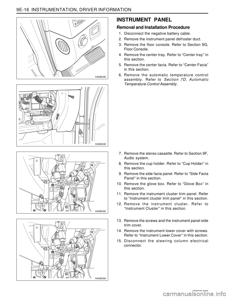
KAA9E250
KAA9E250
7. Remove the stereo cassette. Refer to Section 9F,
Audio system.
8. Remove the cup holder. Refer to “Cup Holder” in
this section.
9. Remove the side facia panel. Refer to “Side Facia
Panel” in this section.
10. Remove the glove box. Refer to “Glove Box” in
this section.
11. Remove the instrument cluster trim panel. Refer
to “Instrument cluster trim panel” in this section.
12. Remove the instrument cluster. Refer to
“Instrument Cluster” in this section.
13. Remove the screws and the instrument panel side
trim cover.
14. Remove the instrument lower cover with screws.
Refer to “Instrument Lower Cover” in this section.
15. Disconnect the steering column electrical
connector.
KAA9E240
INSTRUMENT PANEL
Removal and Installation Procedure
1. Disconnect the negative battery cable.
2. Remove the instrument panel defroster duct.
3. Remove the floor console. Refer to Section 9G,
Floor Console.
4. Remove the center tray. Refer to “Center tray” in
this section.
5. Remove the center facia. Refer to “Center Facia”
in this section.
6. Remove the automatic temperature control
assembly. Refer to Section 7D, Automatic
Temperature Control Assembly.
KAA9E230
Page 1744 of 2053
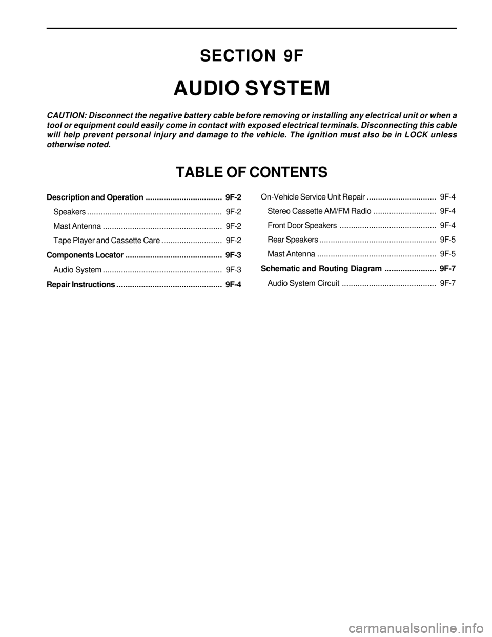
Description and Operation.................................. 9F-2
Speakers............................................................ 9F-2
Mast Antenna..................................................... 9F-2
Tape Player and Cassette Care........................... 9F-2
Components Locator ........................................... 9F-3
Audio System..................................................... 9F-3
Repair Instructions............................................... 9F-4
SECTION 9F
AUDIO SYSTEM
CAUTION: Disconnect the negative battery cable before removing or installing any electrical unit or when a
tool or equipment could easily come in contact with exposed electrical terminals. Disconnecting this cable
will help prevent personal injury and damage to the vehicle. The ignition must also be in LOCK unless
otherwise noted.
TABLE OF CONTENTS
On-Vehicle Service Unit Repair............................... 9F-4
Stereo Cassette AM/FM Radio............................ 9F-4
Front Door Speakers........................................... 9F-4
Rear Speakers.................................................... 9F-5
Mast Antenna..................................................... 9F-5
Schematic and Routing Diagram....................... 9F-7
Audio System Circuit .......................................... 9F-7