Page 579 of 2053
1B3 -- 30 OM600 ENGINE MECHANICAL
D AEW OO M Y_2000
Tools Required
603 589 00 09 00 Serration Wrench
667589036300 SlidingHammer
Removal & Installation Procedure
1. Using the serration wrench (4), remove the threaded
ring (1).
Serration Wrench 603 589 00 09 00
2. Install the sliding hammer into the prechamber.
Sliding Hammer 667 589 03 63 00
3. Remove the perchamber (2).
Notice
After removing the prechamber, cover over the
bores with clean rag.
4. Inspect the prechamber.
Notice
If the prechamber seats in the cylinder head are
leaking or if the prechambers are replaced, the seal-
ing surfaces in the cylinder head must be rema-
chined.
Page 1397 of 2053

TRANSFER CASE 5D1-75
SSANGYONG MY2002
KAA5D510
KAA5D520
KAA5D460
3. Install the front output shaft oil seal using oil seal
installer, if removed.
4. Install the front output shaft/flange and install the
snap ring.
8. Assemble the planetary carrier to the sun gear and
input shaft and install the internal snap ring to the
planetary carrier.
9. While expanding the tanged snap ring with SST
snap ring pliers install planetary carrier assembly.
10. Install the high-low shift fork and collar as an
assembly.
Notice: Make sure that the nylon wear pads are
installed on the shift fork and snapped securely
into place. 6. Slide the sun gear, thrust plate and thrust washer
into position on the input shaft.
Notice: The recessed face of the sun gear and
the snap ring groove on the bearing outer race
should be toward the rear of the transfer case.
The stepped face of the thrust washer should face
toward the bearing.
7. Install the bearing over the input shaft using input
shaft bearing installer SST. Install the external snap
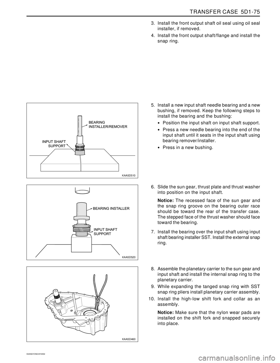
ring. 5. Install a new input shaft needle bearing and a new
bushing, if removed. Keep the following steps to
install the bearing and the bushing:
Position the input shaft on input shaft support.
Press a new needle bearing into the end of the
input shaft until it seats in the input shaft using
bearing remover/installer.
Press in a new bushing.
Page 1525 of 2053

SSANGYONG MY2002
7A-24 HEATING AND VENTILATION SYSTEM
HEATER CORE
Removal and Installation Procedures
1. Disconnect the negative battery cable.
2. Remove the heater/air distribution case from the
vehicle. Refer to “Heater/Air Distribution Case
Assembly” in this section.
3. Remove the plastic holder and two screws that
secure the heater core to heater/air distributor case
assembly.
4. Slowly separate the heater/air distributor case as-
sembly and remove the heater core.
5. Installation should follow the removal procedure
in the reverse order.
REAR HEATER DUCT
This vehicle is equipped with rear seat heater ducts.
Should there be no airflow to the rear, look for any ob-
structions, such as items on the floor under the front
seats. Also check for air leaks between the heater/air
distributor assembly and the rear ducts.
KAA7A190
KAA7D130
KAA7D140
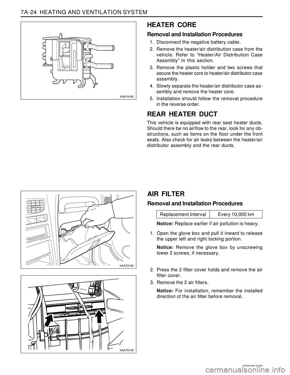
AIR FILTER
Removal and Installation Procedures
Notice: Replace earlier if air pollution is heavy.
1. Open the glove box and pull it inward to release
the upper left and right locking portion.
Notice: Remove the glove box by unscrewing
lower 2 screws, if necessary.
2. Press the 2 filter cover holds and remove the air
filter cover.
3. Remove the 2 air filters.
Notice: For installation, remember the installed
direction of the air filter before removal.
Replacement Interval Every 10,000 km
Page 1755 of 2053
SSANGYONG MY2002
9G-6 INTERIOR TRIM
� �
�
y y
y
KAA9G100
KAA9G090
2. Remove the armrest. Refer to Section 9H “SEATS”.
3. Remove the ashtray and compartment lamp from
lower quarter trim panel.
4. Remove the roof rear trim and back panel cover.
LOWER QUARTER TRIM PANEL
Removal and Installation Procedure
1. Lift up the rear seat from the floor.
KAA9G120
KAA9G110
COWL SIDE TRIM PANEL
Removal and Installation Procedure
1. Remove the cowl side trim panel. Refer to front
rocker trim panel in this section.
2. Remove the cowl side trim panel with the screws.
3. Installation should follow the removal procedure
in the reverse order. 5. Remove the lower quarter trim panel with the
screws.
6. Installation should follow the removal procedure
in the reverse order.
Page 1756 of 2053
INTERIOR TRIM 9G-7
SSANGYONG MY2002
KAA9G140
KAA9G130
FLOOR CONSOLE
Removal and Installation Procedure
1. Remove the screws.
2. Remove the floor console.
3. Disconnect the electrical connector.
4. Installation should follow the removal procedure
in the reverse order.
FRONT ROCKER TRIM PANEL
Removal and Installation Procedure
1. Remove the screws.
2. Remove the rocker trim panel.
3. Installation should follow the removal procedure
in the reverse order.
KAA9G160
KAA9G150
6. Remove the luggage hook with the mounting
screws.
7. Remove the front seat. Refer to Section 9H, Seats.
FLOOR CARPET
Removal and Installation Procedure
1. Disconnect the negative battery cable.
2. Remove the rear seat. Refer to Section 9H, Seats.
3. Remove the bolts and the left and the right lower
seat belt anchors.
4. Remove the child seat anchor. Refer to Section
9H, Seats.
5. Remove the floor carpet screws.
Page 1761 of 2053

SEATS 9H-3
SSANGYONG MY2002
REPAIR INSTRUCTIONS
KAA9H020
ON-VEHICLE SERVICE
UNIT REPAIR
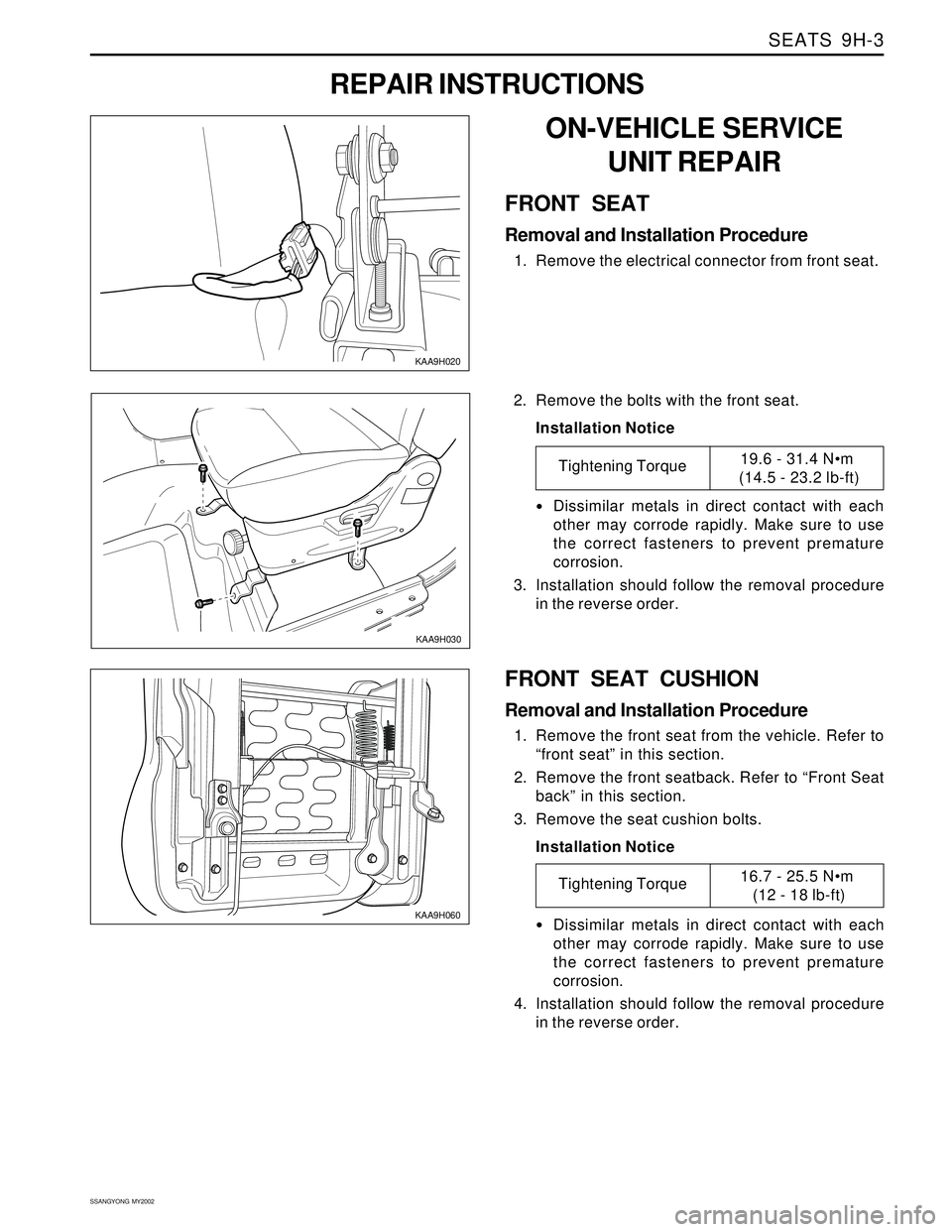
FRONT SEAT
Removal and Installation Procedure
1. Remove the electrical connector from front seat.
KAA9H030
2. Remove the bolts with the front seat.
Installation Notice
•Dissimilar metals in direct contact with each
other may corrode rapidly. Make sure to use
the correct fasteners to prevent premature
corrosion.
3. Installation should follow the removal procedure
in the reverse order.
Tightening Torque19.6 - 31.4 Nm
(14.5 - 23.2 lb-ft)
KAA9H060
FRONT SEAT CUSHION
Removal and Installation Procedure
1. Remove the front seat from the vehicle. Refer to
“front seat” in this section.
2. Remove the front seatback. Refer to “Front Seat
back” in this section.
3. Remove the seat cushion bolts.
Installation Notice
Dissimilar metals in direct contact with each
other may corrode rapidly. Make sure to use
the correct fasteners to prevent premature
corrosion.
4. Installation should follow the removal procedure
in the reverse order.
Tightening Torque16.7 - 25.5 Nm
(12 - 18 lb-ft)
Page 1762 of 2053

SSANGYONG MY2002
9H-4 SEATS
KAA9H070
FRONT SEAT GUIDE RAIL
Removal and Installation Procedure
1. Remove the front seat from the vehicle. Refer to
in this section.
2. Remove the front seat trim. Refer to “front seat
trim” in this section.
3. Remove the bolts and the guide rail.
Installation Notice
KAA9H050
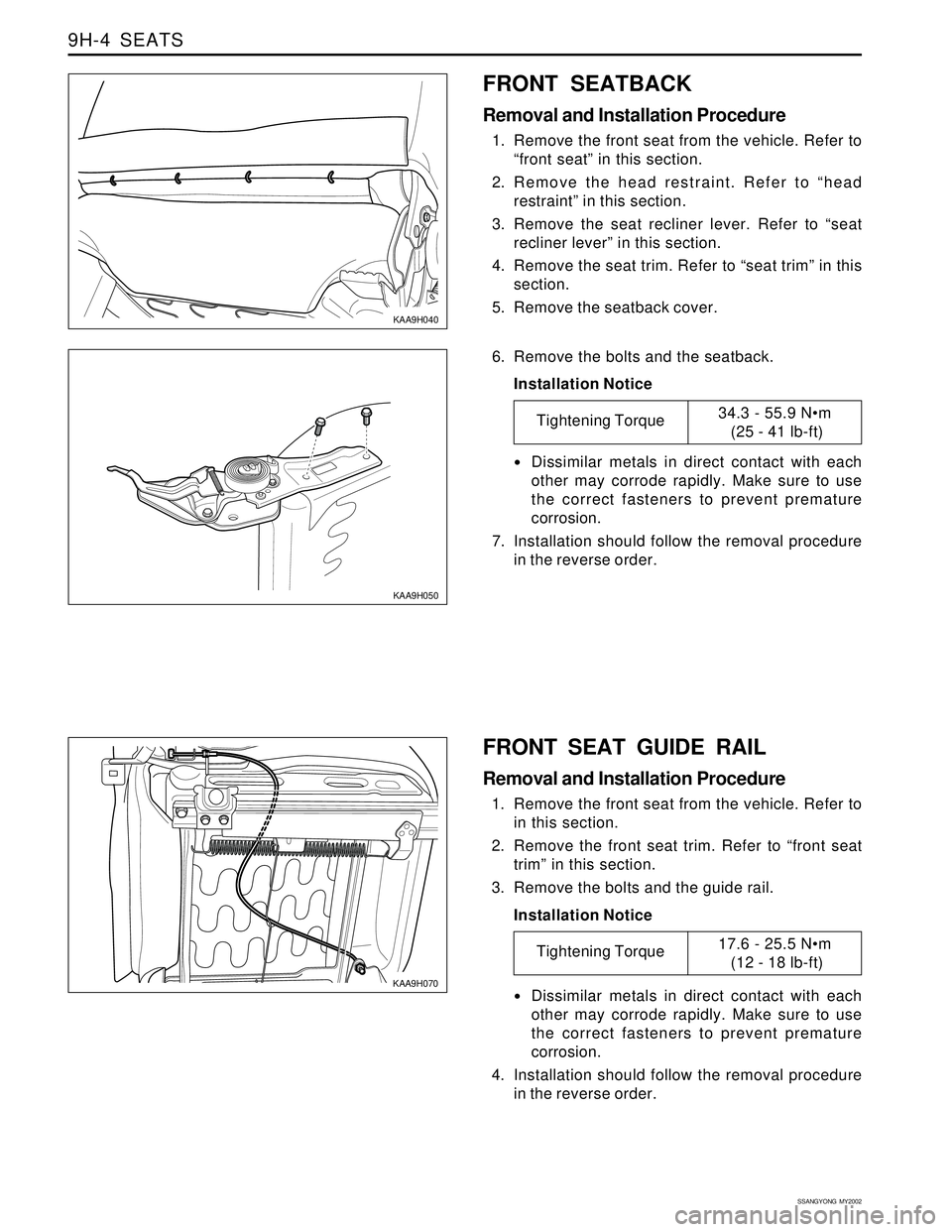
6. Remove the bolts and the seatback.
Installation Notice
Dissimilar metals in direct contact with each
other may corrode rapidly. Make sure to use
the correct fasteners to prevent premature
corrosion.
7. Installation should follow the removal procedure
in the reverse order.
Tightening Torque34.3 - 55.9 Nm
(25 - 41 lb-ft)
Dissimilar metals in direct contact with each
other may corrode rapidly. Make sure to use
the correct fasteners to prevent premature
corrosion.
4. Installation should follow the removal procedure
in the reverse order.
Tightening Torque17.6 - 25.5 Nm
(12 - 18 lb-ft)
KAA9H040
FRONT SEATBACK
Removal and Installation Procedure
1. Remove the front seat from the vehicle. Refer to
“front seat” in this section.
2. Remove the head restraint. Refer to “head
restraint” in this section.
3. Remove the seat recliner lever. Refer to “seat
recliner lever” in this section.
4. Remove the seat trim. Refer to “seat trim” in this
section.
5. Remove the seatback cover.
Page 1763 of 2053
SEATS 9H-5
SSANGYONG MY2002
KAA9H100
KAA9H080
KAA9H090
FRONT SEAT TRIM
Removal and Installation Procedure
1. Remove the recliner lever by rubber hammer. Refer
to “seat recliner lever” in this section.
2. Remove the screws and the seat trim.
3. Installation should follow the removal procedure
in the reverse order.
FRONT SEAT RECLINER LEVER
Removal and Installation Procedure
1. Remove the seat recliner lever by rubber hammer.
2. Installation should follow the removal procedure
in the reverse order.
HEAD RESTRAINT
Removal and Installation Procedure
1. Press in the head restraint adjust button and
remove the head restraint from the seatback.
KAA9H110
2. Insert two flat head screwdrivers down the front
and back side of the guide sleeves.
3. With the screwdrivers, press in the retaining
latches and remove the guide sleeves.
4. Installation should follow the removal procedure
in the reverse order.