1997 SSANGYONG KORANDO ignition
[x] Cancel search: ignitionPage 2 of 2053

0B -- 2 GENERAL INFORMATION
D AEW OO M Y_2000
SPECIFICATIONS
TECHNICAL DATA
Transaxle Performance
Application661LA662NA662LA2.0L
DOHC2.3L
DOCH3.2L
DOCH
Maximum Speed (Km/h)140134148154165176
Minimum Turning Radius (m)5.85.85.85.85.85.8
Performance- Autumatic Transaxle
Application661LA662NA662LA2.3L DOCH3.2L DOCH
Maximum Speed (Km/h)140137140160170
Minimum Turning Radius (m)5.85.85.85.85.8
Engine
Application661LA662NA662LA2.0L
DOHC2.3L
DOCH3.2L
DOCH
Engine Type4Cylinder
DIESEL5Cylinder
DIESEL5Cylinder
DIESEL4Cylinder
GASOLINE4Cylinder
GASOLINE6Cylinder
GASOLINE
Bore (mm)89898989.990.989.9
Stroke (mm)92.492.492.478.788.484
Total Displacement (cc)229928742874199822953199
Compression Ratio22:122:122:19.6:110.4:110:1
Maximum Power (ps/rpm)101/400095/4000120/4000135/5500149/5500222/5500
Maximum Torque (kg.m/rpm)21.5/240019.6/240025.5/240019.3/400022.4/400031.6/3750
Ignition System
Application2.0L DOHC2.3L DOHC2.0L DOHC
Ignition TypeDistributorless Ignition
Ignition Timing (BOTH)6°±2°6°±2°8°±2°
Ignition Sequence1--3--4--21--3--4--21--5--3--6--2--4
Spark Plug Gap (mm)0.8±0.10.8±0.10.8±0.1
Spark Plug MakerBosch, Chapion, Beru
Spark Plug TypeF8DC4 (BOSCH)
C11YCC (CHAMPION)
14F8DU4 (BERU)
Page 9 of 2053

GENERAL INFORMATION 0B -- 9
D AEW OO M Y_2000
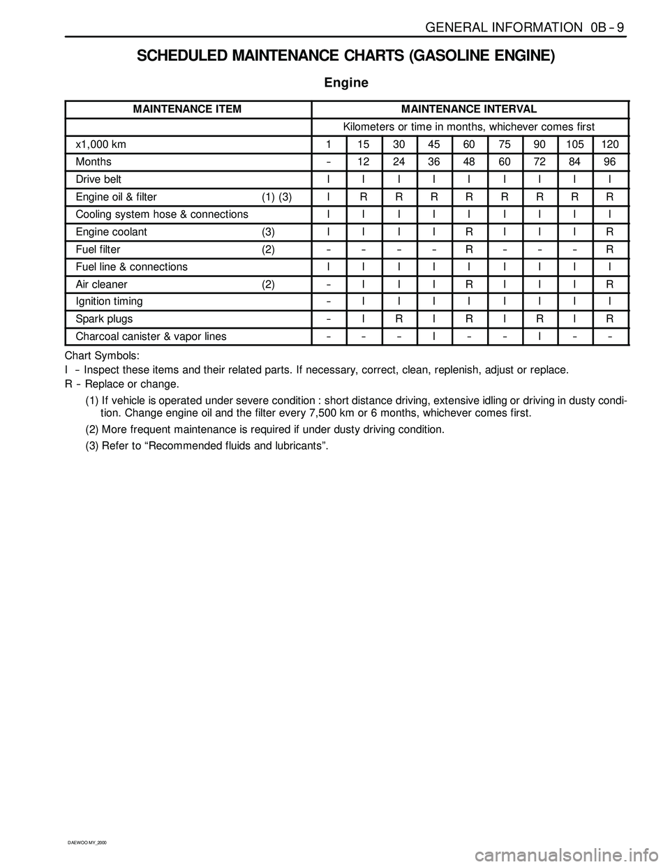
SCHEDULED MAINTENANCE CHARTS (GASOLINE ENGINE)
Engine
MAINTENANCE ITEMMAINTENANCE INTERVAL
Kilometers or time in months, whichever comes first
x1,000 km1153045607590105120
Months--1224364860728496
Drive beltIIIIIIIII
Engine oil & filter (1) (3)IRRRRRRRR
Cooling system hose & connectionsIIIIIIIII
Engine coolant (3)IIIIRIIIR
Fuel filter (2)--------R------R
Fuel line & connectionsIIIIIIIII
Air cleaner (2)--IIIRIIIR
Ignition timing--IIIIIIII
Spark plugs--IRIRIRIR
Charcoal canister & vapor lines------I----I----
Chart Symbols:
I -- Inspect these items and their related parts. If necessary, correct, clean, replenish, adjust or replace.
R -- Replace or change.
(1) If vehicle is operated under severe condition : short distance driving, extensive idling or driving in dusty condi-
tion. Change engine oil and the filter every 7,500 km or 6 months, whichever comes first.
(2) More frequent maintenance is required if under dusty driving condition.
(3) Refer to “Recommended fluids and lubricants”.
Page 11 of 2053

GENERAL INFORMATION 0B -- 11
D AEW OO M Y_2000
SCHEDULED MAINTENANCE CHARTS (DIESEL ENGINE)
Engine
MAINTENANCE ITEMMAINTENANCE INTERVAL
Kilometers or time in months, whichever comes first
x1,000 km1102030405060708090100
Months--6121824303642485460
Drive beltIIIIIIIIIII
Engine oil & fillter (1) (3)RRRRRRRRRRR
Cooling system hose & connections----IIIIIIIII
Engine coolant (3)----I------R------I
Fuel filter (2)--------R--------R--
Fuel line & connectionsIIIIIIIIIII
Glow plug----I--I--I--R--I
Pre -- fuel filter--IIRIIIIIII
Air cleaner (2)--IIIIIRIIRI
Ignition timing (see NOTE 1)--IIIIIIIIII
NOTE 1 : Injection Timing :
Adjust as required :
-- When excessive smoke is visible (black or white)
-- Poor performance/economy
Chart Symbols:
I -- Inspect these items and their related parts. If necessary, correct, clean, replenish, adjust or replace.
R -- Replace or change.
(1) If vehicle is operated under severe condition : short distance driving, extensive idling or driving in dusty condi-
tion, change engine oil every 5,000km or 3 months, whichever comes first.
(2) More frequent maintenance is required if under dusty driving conditing.
(3) Refer to “Recommended fluids and lubricants”.
Page 22 of 2053

1A1 -- 2 GENERAL ENGINE INFORMATION
D AEW OO M Y_2000
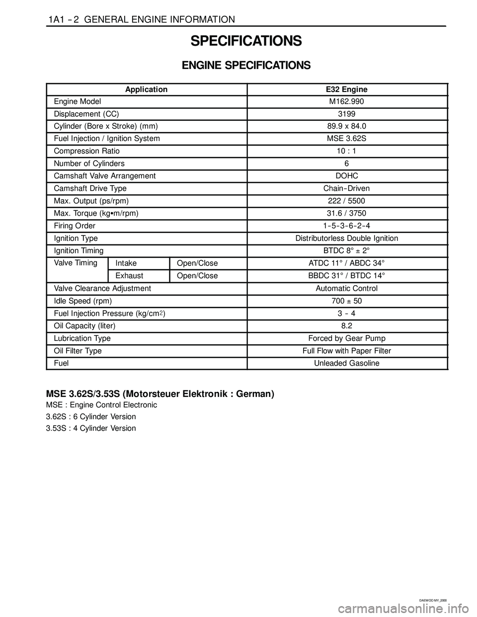
SPECIFICATIONS
ENGINE SPECIFICATIONS
ApplicationE32 Engine
Engine ModelM162.990
Displacement (CC)3199
Cylinder (Bore x Stroke)(mm)89.9 x 84.0
Fuel Injection / Ignition SystemMSE 3.62S
Compression Ratio10 : 1
Number of Cylinders6
Camshaft Valve ArrangementDOHC
Camshaft Drive TypeChain-- Driven
Max. Output (ps/rpm)222 / 5500
Max. Torque (kgSm/rpm)31.6 / 3750
Firing Order1--5--3--6--2--4
Ignition TypeDistributorless Double Ignition
Ignition TimingBTDC 8°±2°
Valve TimingIntakeOpen/CloseAT DC 11°/ ABDC 34°g
ExhaustOpen/CloseBBDC 31°/BTDC14°
Valve Clearance AdjustmentAutomatic Control
Idle Speed (rpm)700±50
Fuel Injection Pressure (kg/cm@)3--4
Oil Capacity (liter)8.2
Lubrication TypeForced by Gear Pump
Oil Filter TypeFull Flow with Paper Filter
FuelUnleaded Gasoline
MSE 3.62S/3.53S (Motorsteuer Elektronik : German)
MSE : Engine Control Electronic
3.62S : 6 Cylinder Version
3.53S : 4 Cylinder Version
Page 32 of 2053

1A1 -- 12 GENERAL ENGINE INFORMATION
D AEW OO M Y_2000
GENERAL INFORMATION
CLEANLINESS AND CARE
An automobile engine is a combination of many ma-
chined, honed, polished and lapped surfaces with toler-
ances that are measured in the ten-thousandths of an
inch. When any internal engine parts are serviced, care
and cleanliness are important. A liberal coating of enigne
oil should be applied to friction areas during assembly, to
protect and lubricate the surfaces on initial operation.
Proper cleaning and protection of machined surfaces and
friction areas is part of the repair procedure. This is con-
sidered standard shop practice even if not specifically
stated.
Whenever valve train components are removed for ser-
vice, they should be kept in order. They should be
installed in the same locations, and with the same mating
surfaces, as when they were removed.
Battery cables should be disconnected before any major
work is performed on the engine. Failure to disconnectcables may result in damage to wire harness or other
electrical parts.
ON-ENGINE SERVICE
Caution: Disconnect the negative battery cable be -
fore removing or installing any electrical unit, or
when a tool or equipment could easily come in con-
tact with exposed electrical terminals. Disconnect -
ing this cable will help prevent personal injury and
damage to the vehicle. The ignition must also be in
LOCK unless otherwise noted.
Notice:Any time the air cleaner is removed, the intake
opening should be covered. Thiswill protect against ac-
cidental entrance of foreign material, which could follow
the intake passage into the cylinder and cause exten-
sive damage when the engine is started.
Page 33 of 2053

D AEW OO M Y_2000
SECTION 1B1
M162 ENGINE MECHANICAL
CAUTION: Disconnect the negative battery cable before removing or installing any electrical unit or when a
tool or equipment could easily come in contact with exposed electrical terminals. Disconnecting this cable
will help prevent personal injury and damage to the vehicle. The ignition must also be in LOCK unless other -
wise noted.
TABLE OF CONTENTS
Specifications 1B1 -- 2............................
Fastener Tightening Specifications 1B1 -- 2..........
Special Tools 1B1 -- 4.............................
Special Tools Table 1B1-- 4.......................
Maintenance and Repair 1B1 -- 7...................
On-- Vehicle Service 1B1-- 7.........................
Engine Assembly 1B1-- 7.........................
Crankcase Ventilation System 1B1-- 14.............
Generator 1B1-- 16..............................
Engine Mount 1B1-- 17...........................
Poly V-- Belt 1B1 -- 18.............................
Tensioning Device 1B1-- 20.......................
Poly V-- Belt Inspection 1B1-- 21...................
Cylinder Head Cover 1B1-- 24.....................
Cylinder Head Front Cover 1B1 -- 26...............
Cylinder Head 1B1-- 28...........................
Timing Gear Case Cover 1B1-- 31.................
Crankshaft Sealing Rear Cover 1B1-- 33...........
Belt Pulley and Vibration Damper 1B1-- 35..........
Crankshaft Front Radial Seal 1B1-- 38.............
Crankshaft Rear Radial Seal 1B1-- 40..............
Crankshaft 1B1-- 41.............................
Flywheel / Driven Plate 1B1 -- 47...................
Camshaft Adjuster 1B1-- 50.......................
Camshaft Sprocket Bolt 1B1-- 52..................
Camshaft 1B1-- 54..............................
Camshaft Timing Position 1B1 -- 59................Valve Spring 1B1 -- 62............................
Valve Stem Seal 1B1-- 66........................
Chain Tensioner 1B1-- 67.........................
Timing Chain 1B1-- 70............................
Tensioning Rail 1B1-- 75..........................
Cylinder Head Guide Rail 1B1-- 76.................
Crankcase Guide Rail 1B1-- 77....................
Crankshaft Sprocket 1B1-- 78.....................
Piston 1B1-- 80..................................
Connecting Rod 1B1-- 83.........................
Piston Ring 1B1 -- 85.............................
Engine Oil Specification 1B1-- 87..................
Oil Pan 1B1-- 88.................................
Engine Oil and Oil Filter Element 1B1-- 90..........
Oil Filter 1B1-- 92................................
Oil Pump 1B1-- 94...............................
Oil Pressure Relief Valve 1B1-- 96.................
Oil Non-Return Valve 1B1-- 97....................
Oil Dipstick Guide Tube 1B1-- 98..................
Unit Repair 1B1 -- 99..............................
Oil Gallery in Crankcase 1B1 -- 99..................
Oil Gallery in Cylinder Head 1B1-- 101..............
Core Plugs in Crankcase 1B1-- 104................
Cylinder Bore 1B1-- 106..........................
Crankcase Mating Surface 1B1-- 108..............
Cylinder Head Mating Surface 1B1-- 110...........
Page 43 of 2053

M162 ENGINE MECHANICAL 1B1 -- 11
D AEW OO M Y_2000
17. Disconnect the terminals from starter motor and re-
move the starter motor.
18. Disconnect the engine main harness ground.
19. Disconnect the engine ground wire.
20. Disconnect following sensors connector.
DHFM sensor.
DCoolant temperature sensor.
D2 knock sensors.
DCamshaft and crankshaft sensors.
21. After removing the ignition coil cover, disconnect the
ignition coil connector.
22. Remove the harness cover and disconnect the 6 in-
jection valve connectors. Disconnect the main har-
ness.
Page 56 of 2053

1B1 -- 24 M162 ENGINE MECHANICAL
D AEW OO M Y_2000
CYLINDER HEAD COVER
1 Ignition Cable Dust Cover
2 Bolt (M6 x 65, 8 pieces)
9--11 NSm (80-- 97 lb-in) .....................
3 Bolt (M6 x 50, 4 pieces)
9--11 NSm (80-- 97 lb-in) .....................
4 Spacer Sleeve
5 Thrust Piece6 Cylinder Head Cover
7 Gasket Replace...........................
8 Spart Plug Hole Seal Replace...............
9 Camshaft Seal Replace.....................
Composition of The Cylinder Head Cover
Bolts
A. M6 x 50, 4 Pieces -- Bolts + Washers
B. M6 x 65, 8 Pieces -- Bolts + Washers