1997 SSANGYONG KORANDO air filter
[x] Cancel search: air filterPage 8 of 2053

0B -- 8 GENERAL INFORMATION
D AEW OO M Y_2000
MAINTENANCE AND REPAIR
MAINTENANCE AND
LUBRICATION
NORMAL VEHICLE USE
The maintenance instructions contained in the mainte-
nance schedule are based on the assumption that the
vehicle will be used for the following reasons:
DTo carry passengers and cargo within the limitation of
the tire inflation prassure. Refer to “Tire and Wheel” in
section 2E.
DTo be driven on reasonable road surfaces and within
legal operating limits.
EXPLANATION OF SCHEDULED
MAINTENANCE SERVICES
The services listed in the maintenance schedule are fur-
ther explained below. When the following maintenance
services are performed, make sure all the parts are re-
placed and all the necessary repairs are done before
driving the vehicle. Always use the proper fluid and lubri-
cants.
Engine Oil and Oil Filter Change
Always use above the API SH grade or recommended
engine oil.
Engine Oil Viscosity
Engine oil viscosity (thickness) has an effect on fuel
economy and cold weather operation. Lower viscosity
engine oils can provide better fuel economy and cold
weather performance; however, higher temperature
weather conditions require higher viscosity engine oils
for satisfactory lubrication. Using oils of any viscosity
other than those viscosities recommended could result
in engine damage.
Cooling System Service
Drain, flush and refill the system with new coolant. Refer
to “Recommended Fluids And Lubricants“ in this sec-
tion.
Air Cleaner Element Replacement
Clean the air cleaner element every.
DGasoline Engine : 15,000km (10,000 miles)
DDiesel Engine : 10,000km (6,000 miles)
Replace the air cleaner element every .
DGasoline Engine : 60,000km (36,000 miles)DDiesel Engine : 30,000km (18,000 miles)
Replace the air cleaner more often under dusty condi-
tions.
Fuel Filter Replacement
Replace the engine fuel filter every.
DGasoline Engine : 60,000km (36,000 miles)
DDiesel Engine : 45,000km (24,000 miles)
Spark Plug Replacement
Replace spark plugs with same type.
DType : BOSCH : F8DC4
BERU : 14F-- 8DU4
Champion : C11YCC
DGap : 0.8±0.1 mm
Spark Plug Wire Replacement
Clean wires and inspect them for burns, cracks or other
damage. Check the wire boot fit at the Distributor and at
the spark plugs. Replace the wires as needed.
Brake System Service
Check the disc brake pads or the drum brake linings.
Check the pad and the lining thickness carefully.
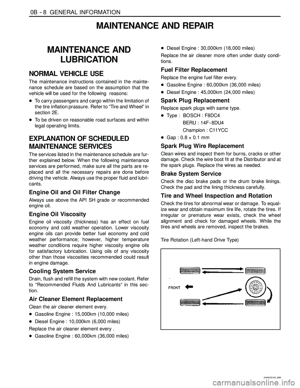
Tire and Wheel Inspection and Rotation
Check the tires for abnormal wear or damage. To equal-
ize wear and obtain maximum tire life, rotate the tires. If
irregular or premature wear exists, check the wheel
alignment and check for damaged wheels. While the
tires and wheels are removed, inspect the brakes.
Tire Rotation (Left-hand Drive Type)
Page 9 of 2053

GENERAL INFORMATION 0B -- 9
D AEW OO M Y_2000
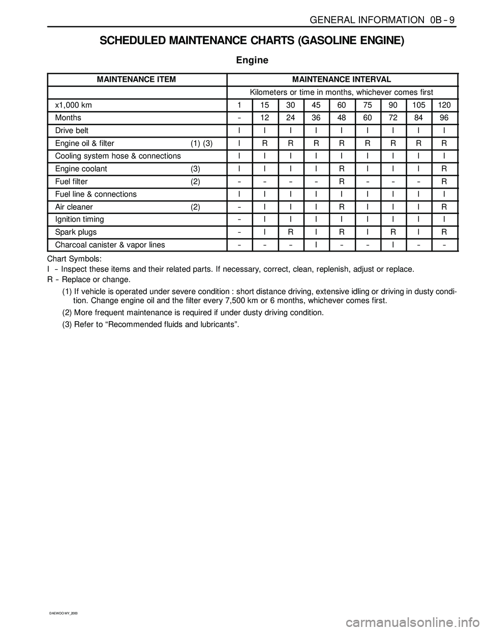
SCHEDULED MAINTENANCE CHARTS (GASOLINE ENGINE)
Engine
MAINTENANCE ITEMMAINTENANCE INTERVAL
Kilometers or time in months, whichever comes first
x1,000 km1153045607590105120
Months--1224364860728496
Drive beltIIIIIIIII
Engine oil & filter (1) (3)IRRRRRRRR
Cooling system hose & connectionsIIIIIIIII
Engine coolant (3)IIIIRIIIR
Fuel filter (2)--------R------R
Fuel line & connectionsIIIIIIIII
Air cleaner (2)--IIIRIIIR
Ignition timing--IIIIIIII
Spark plugs--IRIRIRIR
Charcoal canister & vapor lines------I----I----
Chart Symbols:
I -- Inspect these items and their related parts. If necessary, correct, clean, replenish, adjust or replace.
R -- Replace or change.
(1) If vehicle is operated under severe condition : short distance driving, extensive idling or driving in dusty condi-
tion. Change engine oil and the filter every 7,500 km or 6 months, whichever comes first.
(2) More frequent maintenance is required if under dusty driving condition.
(3) Refer to “Recommended fluids and lubricants”.
Page 11 of 2053

GENERAL INFORMATION 0B -- 11
D AEW OO M Y_2000
SCHEDULED MAINTENANCE CHARTS (DIESEL ENGINE)
Engine
MAINTENANCE ITEMMAINTENANCE INTERVAL
Kilometers or time in months, whichever comes first
x1,000 km1102030405060708090100
Months--6121824303642485460
Drive beltIIIIIIIIIII
Engine oil & fillter (1) (3)RRRRRRRRRRR
Cooling system hose & connections----IIIIIIIII
Engine coolant (3)----I------R------I
Fuel filter (2)--------R--------R--
Fuel line & connectionsIIIIIIIIIII
Glow plug----I--I--I--R--I
Pre -- fuel filter--IIRIIIIIII
Air cleaner (2)--IIIIIRIIRI
Ignition timing (see NOTE 1)--IIIIIIIIII
NOTE 1 : Injection Timing :
Adjust as required :
-- When excessive smoke is visible (black or white)
-- Poor performance/economy
Chart Symbols:
I -- Inspect these items and their related parts. If necessary, correct, clean, replenish, adjust or replace.
R -- Replace or change.
(1) If vehicle is operated under severe condition : short distance driving, extensive idling or driving in dusty condi-
tion, change engine oil every 5,000km or 3 months, whichever comes first.
(2) More frequent maintenance is required if under dusty driving conditing.
(3) Refer to “Recommended fluids and lubricants”.
Page 33 of 2053

D AEW OO M Y_2000
SECTION 1B1
M162 ENGINE MECHANICAL
CAUTION: Disconnect the negative battery cable before removing or installing any electrical unit or when a
tool or equipment could easily come in contact with exposed electrical terminals. Disconnecting this cable
will help prevent personal injury and damage to the vehicle. The ignition must also be in LOCK unless other -
wise noted.
TABLE OF CONTENTS
Specifications 1B1 -- 2............................
Fastener Tightening Specifications 1B1 -- 2..........
Special Tools 1B1 -- 4.............................
Special Tools Table 1B1-- 4.......................
Maintenance and Repair 1B1 -- 7...................
On-- Vehicle Service 1B1-- 7.........................
Engine Assembly 1B1-- 7.........................
Crankcase Ventilation System 1B1-- 14.............
Generator 1B1-- 16..............................
Engine Mount 1B1-- 17...........................
Poly V-- Belt 1B1 -- 18.............................
Tensioning Device 1B1-- 20.......................
Poly V-- Belt Inspection 1B1-- 21...................
Cylinder Head Cover 1B1-- 24.....................
Cylinder Head Front Cover 1B1 -- 26...............
Cylinder Head 1B1-- 28...........................
Timing Gear Case Cover 1B1-- 31.................
Crankshaft Sealing Rear Cover 1B1-- 33...........
Belt Pulley and Vibration Damper 1B1-- 35..........
Crankshaft Front Radial Seal 1B1-- 38.............
Crankshaft Rear Radial Seal 1B1-- 40..............
Crankshaft 1B1-- 41.............................
Flywheel / Driven Plate 1B1 -- 47...................
Camshaft Adjuster 1B1-- 50.......................
Camshaft Sprocket Bolt 1B1-- 52..................
Camshaft 1B1-- 54..............................
Camshaft Timing Position 1B1 -- 59................Valve Spring 1B1 -- 62............................
Valve Stem Seal 1B1-- 66........................
Chain Tensioner 1B1-- 67.........................
Timing Chain 1B1-- 70............................
Tensioning Rail 1B1-- 75..........................
Cylinder Head Guide Rail 1B1-- 76.................
Crankcase Guide Rail 1B1-- 77....................
Crankshaft Sprocket 1B1-- 78.....................
Piston 1B1-- 80..................................
Connecting Rod 1B1-- 83.........................
Piston Ring 1B1 -- 85.............................
Engine Oil Specification 1B1-- 87..................
Oil Pan 1B1-- 88.................................
Engine Oil and Oil Filter Element 1B1-- 90..........
Oil Filter 1B1-- 92................................
Oil Pump 1B1-- 94...............................
Oil Pressure Relief Valve 1B1-- 96.................
Oil Non-Return Valve 1B1-- 97....................
Oil Dipstick Guide Tube 1B1-- 98..................
Unit Repair 1B1 -- 99..............................
Oil Gallery in Crankcase 1B1 -- 99..................
Oil Gallery in Cylinder Head 1B1-- 101..............
Core Plugs in Crankcase 1B1-- 104................
Cylinder Bore 1B1-- 106..........................
Crankcase Mating Surface 1B1-- 108..............
Cylinder Head Mating Surface 1B1-- 110...........
Page 40 of 2053

1B1 -- 8 M162 ENGINE MECHANICAL
D AEW OO M Y_2000
Removal & Installation Procedure
1. Disconnect the negative terminal of battery.
2. Remove the hood.
3. Remove the under cover.
Installation Notice
Tightening Torque
28 -- 47 NSm (21 -- 35 lb-ft)
4. Disconnect the mass air flow sensor meter connec-
tor.
5. Disconnect the mass air flow sensor meter from the
air filter housing.
6. Remove the intake air duct mounting nuts.
Installation Notice
Tightening Torque
9--11NSm (80 -- 97 lb-in)
7. Remove the air cleaner cover. Remove the mounting
bolts and air cleaner housing and element assembly.
8. Loosen the radiator drain cock and drain the coolant.
Notice:Open the coolant reservoir cap.
Page 46 of 2053

1B1 -- 14 M162 ENGINE MECHANICAL
D AEW OO M Y_2000
CRANKCASE VENTILATIONSYSTEM
1 Crankcase
2 Air Admission Port in Crankcase
3 Oil Drain Port
4 Filter
5 Gasket
6 A/C Bracket
7 Oil Drain Pipe
8OilPan
9 Air Admission Line
10 Vent Line
11 Restriction Hole (Diameter = 2 mm)
12 Intake Manifold13 Intake Air Duct (Cross Pipe)
14 Cylinder Head Cover
15 Oil Separator
16 Oil Separator
17 Air Admission and Vent Connection
18 Air Admission and Vent Connection
19 Throttle Valve
20 Vent Line
A Fresh Air
B Blowby Gas in Partial Load
C Blowby Gas in Full Load
Page 164 of 2053

D AEW OO M Y_2000
SECTION 1F1
ENGINE CONTROLS
CAUTION: Disconnect the negative battery cable before removing or installing any electrical unit or when a
tool or equipment could easily come in contact with exposed electrical terminals. Disconnecting this cable
will help prevent personal injury and damage to the vehicle. The ignition must also be in LOCK unless other -
wise noted.
TABLE OF CONTENTS
Engine and ECM Problem Check Report 1F1 -- 2....
Specifications 1F1 -- 3............................
Engine Data Display Table 1F1 -- 3.................
Fastener Tightening Specifications 1F1 -- 4..........
Fuel System Specification 1F1 -- 5.................
Temperature vs Resistance 1F1 -- 5................
Special Tools and Equipment 1F1 -- 6..............
Special Tools Table 1F1 -- 6.......................
Schematic and Routing Diagrams 1F1 -- 7..........
ECM Wiring Diagram
(3.2L DOHC -- MSE 3.62S) 1F1 -- 7..............
Diagnosis 1F1 -- 14................................
Failure Code Diagnosis 1F1 -- 14.....................
Clearing Failure Codes 1F1 -- 14...................
Failure Codes Table 1F1 -- 14.....................
Ignition System 1F1 -- 18...........................
Ignition Coil 1F1 -- 20.............................
Crankshaft Position (CKP) Sensor 1F1 -- 22.........
Camshaft Position (CMP) Sensor 1F1 -- 26..........
Camshaft Actuator 1F1 -- 30......................
Knock Sensor (KS) 1F1 -- 32......................
Spark Plug 1F1 -- 34.............................
System Voltage 1F1 -- 38.........................
Ignition Switch 1F1 -- 39..........................
Fuel System 1F1 -- 40..............................
Fuel Pump 1F1 -- 42.............................
Fuel Injector 1F1 -- 46............................
Purge Control Valve 1F1 -- 50.....................
Fuel Rail 1F1 -- 52...............................
Fuel Pressure Regulator 1F1 -- 54.................
Induction System 1F1 -- 56..........................
Throttle Valve Actuator 1F1 -- 56...................
Hot Film Air Mass (HFM) Sensor 1F1 -- 60..........
Engine Coolant Temperature (ECT) Sensor 1F1 -- 64.
Accelerator Pedal Module 1F1 -- 68................
Clutch Switch 1F1 -- 71...........................Cooling Fan 1F1 -- 72............................
A/C Compressor Relay 1F1 -- 73...................
Cruise Control Switch 1F1 -- 74....................
Traction Control System (TCS) 1F1 -- 75............
Resonance Flap 1F1 -- 76.........................
Stop Lamp Switch 1F1 -- 77.......................
Engine RPM 1F1 -- 78............................
Exhaust System 1F1 -- 79...........................
Catalytic Converter 1F1 -- 79......................
Oxygen Sensor 1F1 -- 80.........................
Engine Control Module 1F1 -- 86.....................
Serial Data Communication 1F1--88...............
Internal Failure 1F1 -- 90..........................
Electronic Throttle Controller Safety
Malfunction 1F1 -- 92...........................
Immobilizer 1F1 -- 94.............................
Maintenance and Repair 1F1 -- 95..................
On -- Vehicle Service 1F1 -- 95........................
Discharging the Pressure in Fuel System 1F1 -- 95...
Fuel Pump 1F1 -- 95.............................
Fuel Filter 1F1 -- 96..............................
Fuel Tank 1F1 -- 97..............................
Fuel Pressure Regulator 1F1 -- 98.................
Fuel Rail and Injector 1F1 -- 99....................
Engine Coolant Temperature Sensor 1F1 -- 100......
Throttle Body (Integrated with the
Actuator) 1F1 -- 101............................
Hot Film Air Mass (HFM) Sensor 1F1 -- 102.........
Knock Sensor 1F1 -- 102..........................
Pedal Position Sensor 1F1 -- 103...................
Oxygen Sensor 1F1 -- 103........................
Purge Control Valve 1F1 -- 104....................
Canister 1F1 -- 104...............................
Camshaft Position Sensor 1F1 -- 104...............
Crankshaft Position Sensor 1F1 -- 105..............
Engine Control Module 1F1 -- 105..................
Page 167 of 2053

1F1 -- 4 M162 ENGINE CONTROLS
D AEW OO M Y_2000
FASTENER TIGHTENING SPECIFICATIONS
ApplicationNSmLb-FtLb-In
Camshaft Position Sensor Retaining Bolts10--89
Canister Mounting Bolts6--53
Coolant Temperature Sensor3022--
Crankshaft Position Sensor Retaining Bolt10--89
Engine Control Module (ECM) Mounting Bracket Nuts10--89
Fuel Filter Mounting Bracket Bolt6--53
Fuel Filter Lines2821--
Fuel Pressure Test Connector2518--
Fuel Rail Assembly Bolts2518--
Fuel Return And Supply Lines2317--
Fuel Tank Retaining Nuts3828--
Intake Air Duct Mounting Bolts9--80
Knock Sensor Mounting Bolt2518--
Oxygen Sensor5541--
Pedal Position Censor Mounting Bolts And Nut6--53
Throttle Body Bolts12--106