1997 SSANGYONG KORANDO instrument panel
[x] Cancel search: instrument panelPage 252 of 2053

M162 ENGINE CONTROLS 1F1 -- 89
D AEW OO M Y_2000
Failure
CodeDescriptionTrouble AreaMaintenance Hint
29
CAN communication
failure: ID 200h not
plausibleWhen CAN signal message
missing or implausibility for
ABS/ABD unit or not
initialized conditionDInspection the ABS/ABD unit with
CAN connection
DInspection the ECM pin 38, 37 about
short circuit or open with bad contact
DInspection the ECM
30
CAN communication
failure: ID 208h not
plausibleWhen CAN signal message
missing or implausibility for
ABS/ABD unit or not
initialized conditionDInspection the ABS/ABD unit with
CAN connection
DInspection the ECM pin 38, 37 about
short circuit or open with bad contact
DInspection the ECM
31
CAN communication
failure: communication
initialization failure
When CAN signal message
missing or implausibility for
each unit (ABS, ASR, TCM,
TOD etc.) or not initialized
conditionDInspection the each control unit with
CAN connection
DInspection the ECM pin 38, 37 about
short circuit or open with bad contact
DInspection the ECM
59
CAN communication
failure: MSR data
transmission not
plausibleWhen CAN signal message
missing or implausibility for
MSR unit or not initialized
condition
DInspection the MSR unit with CAN
connection
DInspection the Engine Control Module
(ECM) pin 38, 37 about short circuit or
open with bad contact
DInspection the ECM
60
CAN communication
failure: ASR data
transmission not
plausibleWhen CAN signal message
missing or implausibility for
ASR unit or not initialized
condition
DInspection the ASR unit with CAN
connection
DInspection the Engine Control Module
(ECM) pin 38, 37 about short circuit or
open with bad contact
DInspection the ECM
Circuit Description
The provision for communicating with the ECM is the Data Link Connector (DLC). It is located in the instrument panel
fuse block. The DLC is used to connect the scan tool. Battery power and ground is supplied for the scan tool through
the DLC. CAN line is used to communicate with the other module such as the Transmission Control Module (TCM) and
Transfer Case Control Unit (TCCU).
Keyword 2000 Serial Data Communications
Each bit of information can have one of two lengths: long or short. This allows vehicle wiring to be reduced by transmit-
ting and receiving multiple signals over a singles wire. The message carried on KWP 2000 data streams are also priori-
tized. If two messages attempt to establish communications on the data line at the same time, only the message with
higher prioritywill must wait.
Page 507 of 2053

M161 ENGINE CONTROLS 1F2 -- 89
D AEW OO M Y_2000
Failure
CodeDescriptionTrouble AreaMaintenance Hint
29
CAN communication
failure: ID 200h not
plausibleWhen CAN signal message
missing or implausibility for
ABS/ABD unit or not
initialized conditionDInspection the ABS/ABD unit with
CAN connection
DInspection the ECM pin 38, 37 about
short circuit or open with bad contact
DInspection the ECM
30
CAN communication
failure: ID 208h not
plausibleWhen CAN signal message
missing or implausibility for
ABS/ABD unit or not
initialized conditionDInspection the ABS/ABD unit with
CAN connection
DInspection the ECM pin 38, 37 about
short circuit or open with bad contact
DInspection the ECM
31
CAN communication
failure: communication
initialization failure
When CAN signal message
missing or implausibility for
each unit (ABS, ASR, TCM,
TOD etc.) or not initialized
conditionDInspection the each control unit with
CAN connection
DInspection the ECM pin 38, 37 about
short circuit or open with bad contact
DInspection the ECM
59
CAN communication
failure: MSR data
transmission not
plausibleWhen CAN signal message
missing or implausibility for
MSR unit or not initialized
condition
DInspection the MSR unit with CAN
connection
DInspection the Engine Control Module
(ECM) pin 38, 37 about short circuit or
open with bad contact
DInspection the ECM
60
CAN communication
failure: ASR data
transmission not
plausibleWhen CAN signal message
missing or implausibility for
ASR unit or not initialized
condition
DInspection the ASR unit with CAN
connection
DInspection the Engine Control Module
(ECM) pin 38, 37 about short circuit or
open with bad contact
DInspection the ECM
Circuit Description
The provision for communicating with the ECM is the Data Link Connector (DLC). It is located in the instrument panel
fuse block. The DLC is used to connect the scan tool. Battery power and ground is supplied for the scan tool through
the DLC. CAN line is used to communicate with the other module such as the Transmission Control Module (TCM) and
Transfer Case Control Unit (TCCU).
Keyword 2000 Serial Data Communications
Each bit of information can have one of two lengths: long or short. This allows vehicle wiring to be reduced by transmit-
ting and receiving multiple signals over a singles wire. The message carried on KWP 2000 data streams are also priori-
tized. If two messages attempt to establish communications on the data line at the same time, only the message with
higher prioritywill must wait.
Page 987 of 2053

ABS AND TCS 4F-3
SSANGYONG MY2002
GENERAL DESCRIPTION AND SYSTEM OPERATION
BASIC KNOWLEDGE REQUIRED
Before using this section, it is important that you have
a basic knowledge of the following items. Without this
knowledge, it will be difficult to use the diagnostic
procedures contained in this section.
•Basic Electrical Circuits - You should understand
the basic theory of electricity and know the meaning
of voltage, current (amps), and resistance (ohms).
You should understand what happens in a circuit
with an open or shorted wire. You should be able to
read and understand a wiring diagram.
Use of Circuit Testing Tools - You should know
how to use a test light and how to bypass
components to test circuits using fused jumper
wires. You should be familiar with a digital
multimeter. You should be able to measure voltage,
resistance, and current, and be familiar with the
controls and how to use them correctly.
ABS SYSTEM COMPONENTS
The ABS 5.3 Antilock Braking System (ABS) consists
of a conventional hydraulic brake system plus antilock
components. The conventional brake system includes
a vacuum booster, master cylinder, front disc brakes,
rear disc brakes, interconnecting hydraulic brake pipes
and hoses, brake fluid level switch and the BRAKE
indicator.
The ABS components include a hydraulic unit, an elec-
tronic brake control module (EBCM), two system fuses,
four wheel speed sensors (one at each wheel), intercon-
necting wiring, the ABS indicator, the EBD indicator
and the TCS indicator. See “ABS Component Locator”
in this section for the general layout of this system.
The hydraulic unit with the attached EBCM is located
between the surge tank and the bulkhead on the left
side of the vehicle.
The basic hydraulic unit configuration consists of hy-
draulic check valves, two solenoid valves for each
wheel, a hydraulic pump, and two accumulators. The
hydraulic unit controls hydraulic pressure to the front
calipers and rear calipers by modulating hydraulic
pressure to prevent wheel lockup.
Units equipped with TCS add two more valves for each
drive wheel for the purpose of applying the brake to a
wheel that is slipping. This is done with pressure from
the hydraulic pump in the unit. There is also a TCS
indicator lamp on the instrument panel to alert the driver
to the fact that the TCS system is active. The
components identified in the drawing are those added
to the basic ABS 5.3 system to provide traction control.
Nothing in the hydraulic unit or the EBCM is serviceable.
In the event of any failure, the entire ABS unit withattached EBCM must be replaced. For more
information, refer to “Base Braking Mode” and
“Antilock Braking Mode” in this section.
TRACTION CONTROL SYSTEM
(TCS) DESCRIPTION
General Information
The traction control system (TCS) is a traction system
by means of brake intervention only, available in a low
speed range (< 60kph).
It workes on µ - split roads with sidewise different friction
coefficients.
The spinning driven wheel is braked and the drive
torque can be transferred to the wheel on the high-µ
side. During TCS active, the TCS information lamp is
blinking.
The temperature of the brakes is calculated by a mathe-
matical model and TCS is switched passive if the calcu-
lated temperature is greater than a threshold value (500
°C).
TCS is permitted again, when the calculated tempera-
ture is less than 350 °C.
Control Algorithm
The input signals for the control algorithm are the
filtered wheel speed signals from the ABS speed
processing.
With the speed difference of the driven wheels, the
control deviation is calculated.
If the control deviation exceeds a certain threshold
value, the wheel with the greater slip is braked actively.
The threshold value depends on the vehicle speed:
It is reduced with increasing vehicle speed down to a
constant value.
KAA4F010
Page 1089 of 2053
SSANGYONG MY2002
4G-2 PARKING BRAKE
DESCRIPTION AND OPERATION
BRAKE CALIPER
This braking system uses a BRAKE warning light lo-
cated in the instrument panel cluster.
The following conditions will activate the BRAKE lamp:
•The parking brake is applied when the ignition is
ON. The lamp will turn off when the parking brake
is released.
The fluid level is below the minimum mark in the
master cylinder reservoir. The lamp will turn off when
the fluid level is above the minimum.
As a test of the lamp circuit, the BRAKE lamp will
glow dimly when the ignition is ON, even if the
parking brake is off and fluid level is above the
minimum. The lamp will turn off when the engine is
started. When the brake is firmly applied, the parking
brake should hold the vehicle with ample pedal
travel remaining.
Check for frayed cables, rust, etc. or any condition
that may inhibit present (or future) free movement of
the parking brake lever assembly.
Page 1092 of 2053
PARKING BRAKE 4G-5
SSANGYONG MY2002
KAA4G040
KAA4G050
KAA4G060
KAA4G070
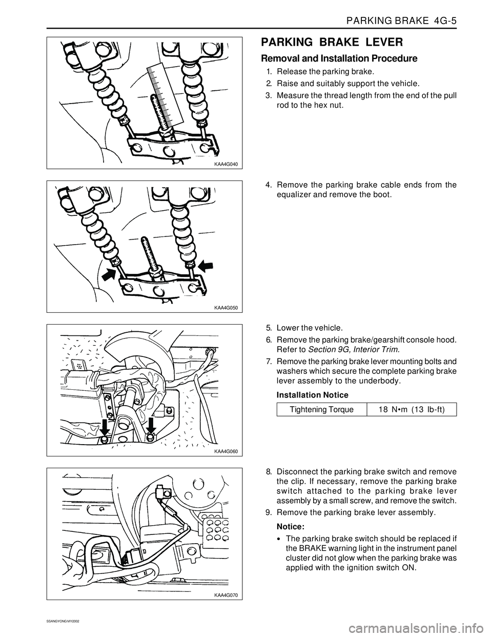
PARKING BRAKE LEVER
Removal and Installation Procedure
1. Release the parking brake.
2. Raise and suitably support the vehicle.
3. Measure the thread length from the end of the pull
rod to the hex nut.
5. Lower the vehicle.
6. Remove the parking brake/gearshift console hood.
Refer to Section 9G, Interior Trim.
7. Remove the parking brake lever mounting bolts and
washers which secure the complete parking brake
lever assembly to the underbody.
Installation Notice
8. Disconnect the parking brake switch and remove
the clip. If necessary, remove the parking brake
switch attached to the parking brake lever
assembly by a small screw, and remove the switch.
9. Remove the parking brake lever assembly.
Notice:
The parking brake switch should be replaced if
the BRAKE warning light in the instrument panel
cluster did not glow when the parking brake was
applied with the ignition switch ON.
Tightening Torque 18 Nm (13 lb-ft) 4. Remove the parking brake cable ends from the
equalizer and remove the boot.
Page 1097 of 2053
AUTOMATIC TRANSMISSION 5A-3
SSANGYONG MY2002
N - Neutral allows the engine to be started and oper-
ated while driving the vehicle. The inhibitor switch
allows the engine to be started. There is no power
transferred through the transmission in Neutral. But
the final drive is not locked by the parking pawl, so
thewheels are free to rotate.
D - Overdrive range is used for all normal driving
conditions. 4th gear (overdrive gear) reduces the
fuel consumption and the engine noise. Engine
braking is applied with reduced throttle.
First to second (1 → 2), first to third (1 → 3), second
to third (2 → 3), second to fourth (2 → 4), third to
fourth (3 → 4), fourth to third (4 → 3), fourth to
second (4 → 2), third to second (3 → 2), third to
first (3 → 1) and second to first (2 → 1) shifts are
all available as a function of vehicle speed, throttle
position and the time change rate of the throttle
position.
Downshifts are available for safe passing by
depress-ing the accelerator. Lockup clutch may be
enabled in 3rd and 4th gears depending on vehicle
type.
3 - Manual 3 provides three gear ratios (first through
third) and prevents the transmission from operating
in 4th gear. 3rd gear is used when driving on long
hill roads or in heavy city traffic. Downshifts are
available by depressing the accelerator.
2 - Manual 2 provides two gear ratios (first and
second). It is used to provide more power when
climbing hills or engine braking when driving down
a steep hill or starting off on slippery roads.
1 - Manual 1 is used to provide the maximum engine
braking when driving down the severe gradients.When NORMAL mode is selected upshifts will occur
to maximize fuel economy. When POWER mode is se-
lected, upshifts will occur to give maximum
performance and the POWER mode indicator light is
switched ON.
When WINTER mode is selected, starting in second
gear is facilitated, the WINTER mode indicator light is
switched ON and the POWER mode indicator light is
switched OFF.
Indicator Light
The indicator light is located on the instrument panel.
Auto shift indicator light comes ON when the ignition
switch ON and shows the gear shift control lever
position.
POWER mode indicator light comes ON when the
POWER mode is selected and when the kickdown
switch is depressed.
WINTER mode indicator light comes ON when the
WINTER mode is selected.
CONTROL SYSTEMS
BTRA M74 4WD automatic transmission consists of
two control systems. One is the electronic control
system that monitors vehicle parameters and adjusts
the transmission performance. Another is the hydraulic
control system that implements the commands of the
electronic control system commands.
ELECTRONIC CONTROL SYSTEM
The electronic control system comprises of sensors, a
TCM and seven solenoids. The TCM reads the inputs
and activates the outputs according to values stored
in Read Only Memory (ROM).
The TCM controls the hydraulic control system. This
control is via the hydraulic valve body, which contains
seven electromagnetic solenoids. Six of the seven
solenoids are used to control the line pressure, operate
the shift valves and the torque converter lock-up clutch,
and to turn ON and OFF the two regulator valves that
control the shift feel.
The seventh solenoid is the proportional or Variable
Pressure Solenoid (VPS) which works with the two regu-
lator valves to control shift feel.
Transmission Control Module (TCM)
The TCM is an in-vehicle micro-processor based trans-
mission management system. It is mounted under the
driver’s side front seat in the vehicle cabin.
The TCM contains:
Processing logic circuits which include a central mi-
croprocessor controller and a back-up memory
system.
Input circuits.
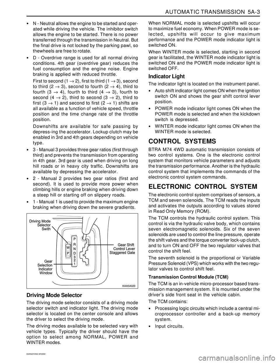
Driving Mode Selector
The driving mode selector consists of a driving mode
selector switch and indicator light. The driving mode
selector is located on the center console and allows
the driver to select the driving mode.
The driving modes available to be selected vary with
vehicle types. Typically the driver should have the
option to select among NORMAL, POWER and
WINTER modes.
KAA5A020
Page 1103 of 2053
AUTOMATIC TRANSMISSION 5A-9
SSANGYONG MY2002
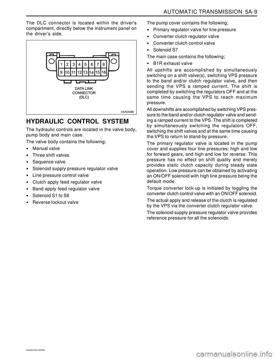
The DLC connector is located within the driver’s
compartment, directly below the instrument panel on
the driver’s side.
HYDRAULIC CONTROL SYSTEM
The hydraulic controls are located in the valve body,
pump body and main case.
The valve body contains the following;
Manual valve
Three shift valves
Sequence valve
Solenoid supply pressure regulator valve
Line pressure control valve
Clutch apply feed regulator valve
Band apply feed regulator valve
Solenoid S1 to S6
Reverse lockout valveThe pump cover contains the following;
Primary regulator valve for line pressure
Converter clutch regulator valve
Converter clutch control valve
Solenoid S7
The main case contains the following;
B1R exhaust valve
All upshifts are accomplished by simultaneously
switching on a shift valve(s), switching VPS pressure
to the band and/or clutch regulator valve, and then
sending the VPS a ramped current. The shift is
completed by switching the regulators OFF and at the
same time causing the VPS to reach maximum
pressure.
All downshifts are accomplished by switching VPS pres-
sure to the band and/or clutch regulator valve and send-
ing a ramped current to the VPS. The shift is completed
by simultaneously switching the regulators OFF,
switching the shift valves and at the same time causing
the VPS to return to stand-by pressure.
The primary regulator valve is located in the pump
cover and supplies four line pressures; high and low
for forward gears, and high and low for reverse. This
pressure has no effect on shift quality and merely
provides static clutch capacity during steady state
operation. Low pressure can be obtained by activating
an ON/OFF solenoid with high line pressure being the
default mode.
Torque converter lock-up is initiated by toggling the
converter clutch control valve with an ON/OFF solenoid.
The actual apply and release of the clutch is regulated
by the VPS via the converter clutch regulator valve.
The solenoid supply pressure regulator valve provides
reference pressure for all the solenoids.
KAA5A080
Page 1134 of 2053
5A-40 AUTOMATIC TRANSMISSION
SSANGYONG MY2002
Dye and Black Light Method
1. Add dye to the transmission through the transmission
fluid filler plug. Follow the manufacturer’s recommen-
dation for the amount of dye to be used.
2. Use the black light to find the fluid leak.
3. Make the necessary repairs.
Repairing the Fluid Leak
Once the leak point is found the source of the leak
must be determined. The following list describes the
potential causes for the leak:
Fasteners are not torqued to specification.
Fastener threads and fastener holes are dirty or
corroded.
Gaskets, seals or sleeves are misaligned, damaged
or worn.
Damaged, warped or scratched seal bore or gasket
surface.
Loose or worn bearing causing excess seal or sleeve
wear.
Case or component porosity.
Fluid level is too high.
Plugged vent or damaged vent tube.
Water or coolant in fluid.
Fluid drain back holes plugged.
ELECTRICAL / GARAGE SHIFT
TEST
This preliminary test should be performed before a hoist
or road test to make sure electronic control inputs are
connected and operating. If the inputs are not checked
before operating the transmission, a simple electrical
condition could be misdiagnosed as a major
transmission condition.
A scan tool provides valuable information and must
be used on the automatic transmission for accurate
diagnosis.
1. Move gear shift control lever to P (Park) and set
the parking brake.
2. Connect scan tool to Data Link Connector (DLC)
terminal.
3. Start engine.
4. Turn the scan tool ON.
5. Verify that the appropriate signals are present.
These signals may include:
ENGINE SPEED
VEHICLE SPEED
THROTTLE POSITION
ACCEL. PEDAL POSITION
TRANSMISSION GEAR STATE
GEAR SHIFT LEVER POSITION
TRANSMISSION FLUID TEMPERATURE
CLOSED THROTTLE POSITION LEARN
OPEN THROTTLE POSITION LEARNT
CLOSED ACCEL. PEDAL POSITION LEARNT
OPEN ACCEL. PEDAL POSITION LEARNT
A/C COMPRESSOR STATUS
KICKDOWN SWITCH STATUS
4WD STATUS
MODE SWITCH
THROTTLE POSITION VOLTAGE
GEAR SHIFT LEVER POSITION VOLTAGE
TRANS. FLUID TEMPERATURE VOLTAGE
A/C SWITCH
KICKDOWN SWITCH VOLTAGE
4WD LAMP LOW VOLTAGE
4WD LAMP HIGH VOLTAGE
MODE SWITCH VOLTAGE
BATTERY VOLTAGE
6. Monitor the A/C COMPRESSOR STATUS signal
while pushing the A/C switch.
The A/C COMPRESSOR STATUS should come
ON when the A/C switch is pressed, and turn
OFF when the A/C switch is repushed.
7. Monitor the GEAR SHIFT LEVER POSITION signal
and move the gear shift control lever through all
the ranges.
Verify that the GEAR SHIFT LEVER POSITION
value matches the gear range indicated on the
instrument panel or console.
Gear selections should be immediate and not
harsh.
8. Move gear shift control lever to neutral and monitor
the THROTTLE POSITION signal while increasing
and decreasing engine speed with the accelerator
pedal.
THROTTLE POSITION should increase with en-
gine speed.
ROAD TEST PROCEDURE
Perform the road test using a scan tool.
This test should be performed when traffic and road
conditions permit.
Observe all traffic regulations.
ELECTRONIC ADJUSTMENTS
Idle Speed Adjustments
Carry out the adjustments to the idle speed as detailed
in the workshop manual.
Vehicle Coding
The vehicle coding is integrated as part of the
diagnostic software. A scan tool has the function to
code the ve-hicle through the K-line.