1997 SSANGYONG KORANDO instrument panel
[x] Cancel search: instrument panelPage 1135 of 2053
5A-40 AUTOMATIC TRANSMISSION
SSANGYONG MY2002
Dye and Black Light Method
1. Add dye to the transmission through the transmission
fluid filler plug. Follow the manufacturer’s recommen-
dation for the amount of dye to be used.
2. Use the black light to find the fluid leak.
3. Make the necessary repairs.
Repairing the Fluid Leak
Once the leak point is found the source of the leak
must be determined. The following list describes the
potential causes for the leak:
Fasteners are not torqued to specification.
Fastener threads and fastener holes are dirty or
corroded.
Gaskets, seals or sleeves are misaligned, damaged
or worn.
Damaged, warped or scratched seal bore or gasket
surface.
Loose or worn bearing causing excess seal or sleeve
wear.
Case or component porosity.
Fluid level is too high.
Plugged vent or damaged vent tube.
Water or coolant in fluid.
Fluid drain back holes plugged.
ELECTRICAL / GARAGE SHIFT
TEST
This preliminary test should be performed before a hoist
or road test to make sure electronic control inputs are
connected and operating. If the inputs are not checked
before operating the transmission, a simple electrical
condition could be misdiagnosed as a major
transmission condition.
A scan tool provides valuable information and must
be used on the automatic transmission for accurate
diagnosis.
1. Move gear shift control lever to P (Park) and set
the parking brake.
2. Connect scan tool to Data Link Connector (DLC)
terminal.
3. Start engine.
4. Turn the scan tool ON.
5. Verify that the appropriate signals are present.
These signals may include:
ENGINE SPEED
VEHICLE SPEED
THROTTLE POSITION
ACCEL. PEDAL POSITION
TRANSMISSION GEAR STATE
GEAR SHIFT LEVER POSITION
TRANSMISSION FLUID TEMPERATURE
CLOSED THROTTLE POSITION LEARN
OPEN THROTTLE POSITION LEARNT
CLOSED ACCEL. PEDAL POSITION LEARNT
OPEN ACCEL. PEDAL POSITION LEARNT
A/C COMPRESSOR STATUS
KICKDOWN SWITCH STATUS
4WD STATUS
MODE SWITCH
THROTTLE POSITION VOLTAGE
GEAR SHIFT LEVER POSITION VOLTAGE
TRANS. FLUID TEMPERATURE VOLTAGE
A/C SWITCH
KICKDOWN SWITCH VOLTAGE
4WD LAMP LOW VOLTAGE
4WD LAMP HIGH VOLTAGE
MODE SWITCH VOLTAGE
BATTERY VOLTAGE
6. Monitor the A/C COMPRESSOR STATUS signal
while pushing the A/C switch.
The A/C COMPRESSOR STATUS should come
ON when the A/C switch is pressed, and turn
OFF when the A/C switch is repushed.
7. Monitor the GEAR SHIFT LEVER POSITION signal
and move the gear shift control lever through all
the ranges.
Verify that the GEAR SHIFT LEVER POSITION
value matches the gear range indicated on the
instrument panel or console.
Gear selections should be immediate and not
harsh.
8. Move gear shift control lever to neutral and monitor
the THROTTLE POSITION signal while increasing
and decreasing engine speed with the accelerator
pedal.
THROTTLE POSITION should increase with en-
gine speed.
ROAD TEST PROCEDURE
Perform the road test using a scan tool.
This test should be performed when traffic and road
conditions permit.
Observe all traffic regulations.
ELECTRONIC ADJUSTMENTS
Idle Speed Adjustments
Carry out the adjustments to the idle speed as detailed
in the workshop manual.
Vehicle Coding
The vehicle coding is integrated as part of the
diagnostic software. A scan tool has the function to
code the ve-hicle through the K-line.
Page 1374 of 2053
SSANGYONG MY2002
5D1-4 TRANSFER CASE
COMPONENTS OF THE TOD
TRANSFER CASE SYSTEM
Shift Motor
It locates backside transfer case, which drives rotary
helical cam. When mode select switch changes to 4L,
shift fork is on position for 2.48 : 1 by rotation of helical
cam.
Rear Speed Sensor
A hall effect speed sensor which produces a square
wave. 0 to 5 volts direct current signal in response to
a rotating 30-tooth wheel coupled to the rear propeller
shaft inside the transfer case. Each rotation of the rear
propeller shaft will result in 30 speed sensor pulse.
Front Speed Sensor
A hall effect speed sensor which produces a square
wave. 0 to 5 volts direct current signal in response to
a rotating 30-tooth wheel coupled to the front propeller
shaft inside the transfer case. Each rotation of the front
propeller shaft will result in 30 speed sensor pulse.
Electro-Magnetic Clutch
An electromagnetic clutch used to control the amount
of torque applied to the front propeller shaft.
Position Encoder
A set of 4 gray code switches which provide feedback
to the TCCU indicating the position of the shift motor.
Clutch Pedal Position Switch
A switch on vehicles equipped with a manual transmis-
sion which indicates that the clutch pedal is depressed
Park/Neutral Position Switch
A switch on vehicles equipped with an automatic trans-
mission which indicates that the transmission is in neu-
tral.
4H/4L Switch
A switch selects the desired gear ratio.
DEFINITION OF TERMINOLOGY
Shift Inhibit Speed
The vehicle speed limit, which transfer case shifts, is
disallowed. Vehicle speed is indicated by propeller
shaft speed measurement.
Duty Cycle
Duty cycle is the time the electromagnetic clutch is on
divided by the period in which it is being modulated.
Touch-off
A minimum amount of duty cycle applied to the electro
magnetic clutch.
Front Overrun
A condition where the front propeller shaft is turning at
a rate which is faster than the rear propeller shaft.
Rear Overrun
A condition where the rear propeller shaft is turning at
a rate which is faster than the front propeller shaft.
High Range
The highest (numerically lowest = 1 : 1) gear ratio be-
tween the input and outputs of the transfer case.
Low Range
The lowest (numerically highest = 2.48 : 1) gear ratio
between the input and outputs of the transfer case.
OPERATION OF THE TOD
TRANSFER CASE SYSTEM
Initial Operation of TOD Control Unit
When ignition switch is turned to ON, 4WD LOW and
4WD CHECK lamp illuminates for 0.6 second to check
bulb in instrument panel, then perform diagnosis of
system. Refer to “Self-Diagnosis Test” in this section.
Electric Shift System Operation
The electric shift system is responsible for changing
the transfer case gear ratio by controlling the electric
shift motor. The TCCU monitors the 4H/4L switch, park/
neutral position switch, speed sensors, position
encoder, and ignition switch.
A range change is initiated when:
The 4H/4L switch is changed from 4H to 4L or from
4L to 4H.
The motor position (as indicated by the position
encoder) does not match the 4H/4L switch
immediately after the ignition is turned on.
Shift Criteria
When a range change is initiated a diagnostic test will
be completed on the motor, speed sensors, and
position encoder. If the diagnostic test fails, the shift
will not be attempted. If all components are operating
properly, the TCCU will attempt a range change after
the following shift criteria are met:
The transmission is in neutral for 2 seconds after
the shift is requested.
Both propeller shaft speeds are below 87 rpm (2580
pulses/minute). If the transmission is taken out of
neutral before 2 seconds has passed, or either
propeller shaft speed increases above the limit, the
shift will be suspended and the 4L indicator will
continue to blink until the criteria are met again or
the 4H/4L switch is returned to the original position.
Range Change
When the shift criteria are met, the motor is rotated in
the appropriate direction (as determined by the selector
switch) until one of the following occurs:
Page 1498 of 2053
SSANGYONG MY2002
6E-12 POWER STEERING AND COLUMN
KAA6E040
KAA6E120
STEERING COLUMN
Important: Remove the steering column only if the
following conditions exist:
The steering column requires replacement.
The steering and the ignition lock housing require
replacement.
Another operation requires the removal of the
steering column
Notice: The steering column is extremely
susceptible to damage after it has been removed
from the vehicle. Dropping the column assembly
on its end or hammering the end of the steering
shaft can collapse the steering shaft or loosen the
plastic injections which maintain column rigidity.
Leaning on the column can cause it to bend or
deform. Any of the above damage can impair the
column’s collapsible design. If it is necessary to
remove the steering wheel, use only the specified
steering wheel puller.
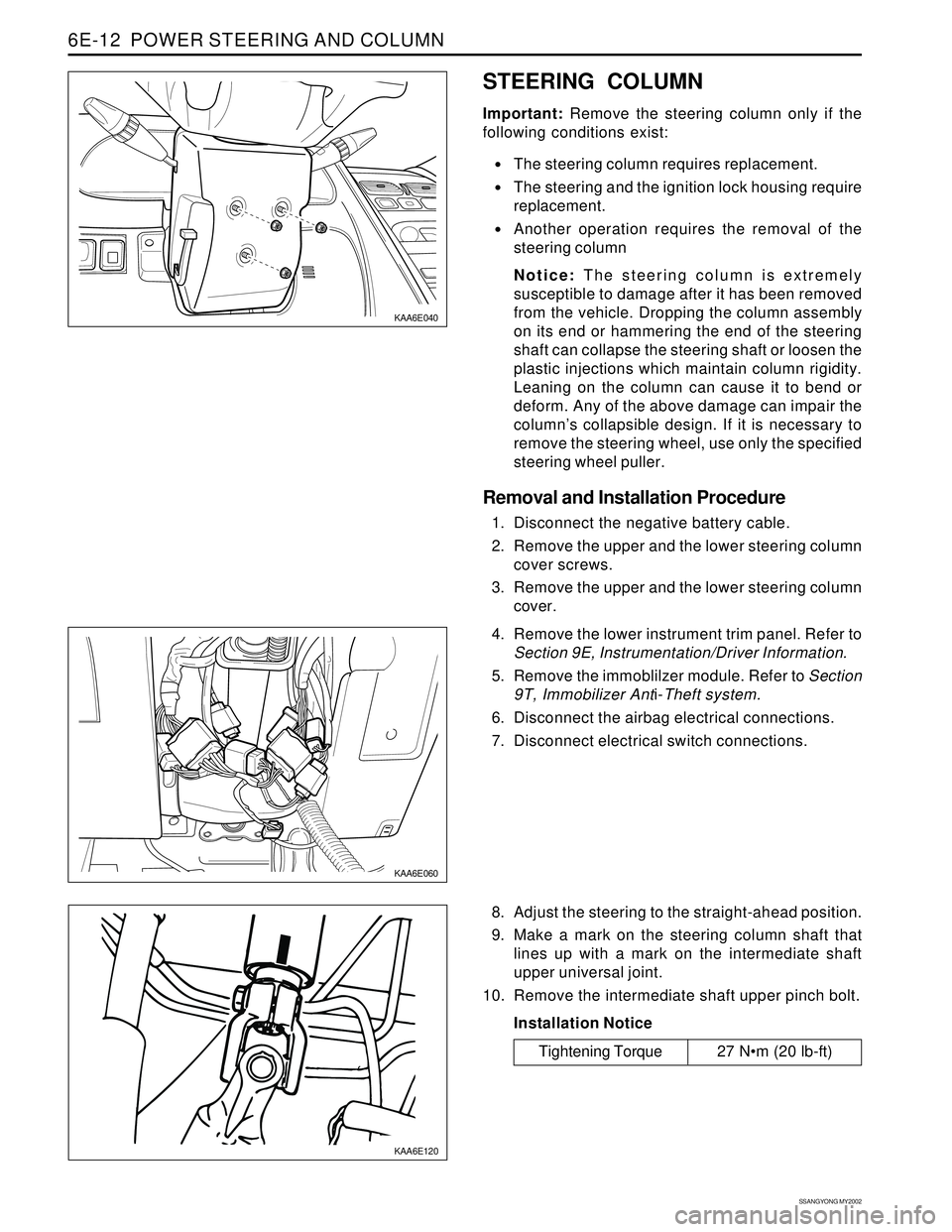
Removal and Installation Procedure
1. Disconnect the negative battery cable.
2. Remove the upper and the lower steering column
cover screws.
3. Remove the upper and the lower steering column
cover.
KAA6E060
4. Remove the lower instrument trim panel. Refer to
Section 9E, Instrumentation/Driver Information.
5. Remove the immoblilzer module. Refer to Section
9T, Immobilizer Anti-Theft system.
6. Disconnect the airbag electrical connections.
7. Disconnect electrical switch connections.
8. Adjust the steering to the straight-ahead position.
9. Make a mark on the steering column shaft that
lines up with a mark on the intermediate shaft
upper universal joint.
10. Remove the intermediate shaft upper pinch bolt.
Installation Notice
Tightening Torque 27 Nm (20 lb-ft)
Page 1503 of 2053
SSANGYONG MY2002
7A-2 HEATING AND VENTILATION SYSTEM
DESCRIPTION AND OPERATION
HEATING AND VENTILATION
SYSTEM
The base heater system is designed to provide heating,
ventilation, windshield defrosting, side wind defogging
and rear seat area.
The heater and fan assembly blower regulates the air-
flow from the air inlet for further processing and distribu-
tion.
The heater core transfers the heater from the engine
coolant to the inlet air.
The temperature door regulates the amount of the air
that passes through the heater core. The temperature
door also controls the temperature of the air by control-
ling mix of heated air with the ambient air.
The mode door regulates the flow and distribution of
the processed air to the heater ducts and to the defroster
ducts.
The console mounted heating and ventilation control
panel contains one rotary control knob, one sliding con-
trol lever and six push control knobs, which operate as
follows:
Sliding Temperature Control Lever
•Actuates by cable.
Raise the temperature of the air entering the vehicle
by sliding to the right, or the red portion of the knob.
Five Mode Control Knob
Actuates by electricity.
Regulates the air distribution between the
windshield, the instrument panel, and the floor
vents.
Rotary Blower Control Knob
Turns on to operate the blower motor at four speeds.
Turns OFF to stop the blower.
Operates completely independently from both the
mode control knob and temperature control knob.
Changes the fan speed in any mode and at any
speed.
Intake Air Control Knob
Operates by electricity.
Switches between recirculating the passenger
compartment air and bringing outside air into the
passenger compartment.
Is normally in fresh air mode.
Illuminates the indicator lamp when in the recalculat
ing mode.
Heater Core
The heater core heats the air before enters the vehicle.
Engine coolant is circulated through the core to heat
the outside air passing over the fins of the core. The
core is functional at all times and may be used to
temper conditioned air in the A/C mode as well as in
the heat or the vent mode.
Page 1514 of 2053
HEATING AND VENTILATION SYSTEM 7A-13
SSANGYONG MY2002
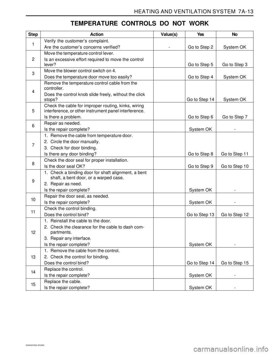
TEMPERATURE CONTROLS DO NOT WORK
Step
1
2
3
4
5
6
7
8
9
10
11
12
13
14
15Action
Verify the customer’s complaint.
Are the customer’s concerns verified?
Move the temperature control lever.
Is an excessive effort required to move the control
lever?
Move the blower control switch on 4.
Does the temperature door move too easily?
Remove the temperature control cable from the
controller.
Does the control knob slide freely, without the click
stops?
Check the cable for improper routing, kinks, wiring
interference, or other instrument panel interference.
Is there a problem.
Repair as needed.
Is the repair complete?
1. Remove the cable from temperature door.
2. Circle the door manually.
3. Check for door binding.
Is there any door binding?
Check the door seal for proper installation.
Is the door seal OK?
1. Check a binding door for shaft alignment, a bent
shaft, a bent door, or a warped case.
2. Repair as need.
Is the repair complete?
Repair the door seal, as needed.
Is the repair complete?
Check the control binding.
Does the control bind?
1. Reinstall the cable to the door.
2. Check the clearance for the cable to dash com-
partments.
3. Repair any interface.
Is the repair complete?
1. Remove the cable from the control.
2. Check the control for binding.
Does the control bind?
Replace the control.
Is the repair complete?
Replace the cable.
Is the repair complete?Yes
Go to Step 2
Go to Step 5
Go to Step 4
Go to Step 14
Go to Step 6
System OK
Go to Step 8
Go to Step 9
System OK
System OK
Go to Step 13
System OK
Go to Step 14
System OK
System OKNo
System OK
Go to Step 3
System OK
System OK
Go to Step 7
-
Go to Step 11
Go to Step 10
-
-
Go to Step 12
-
Go to Step 15
-
-Value(s)
-
Page 1521 of 2053
SSANGYONG MY2002
7A-20 HEATING AND VENTILATION SYSTEM
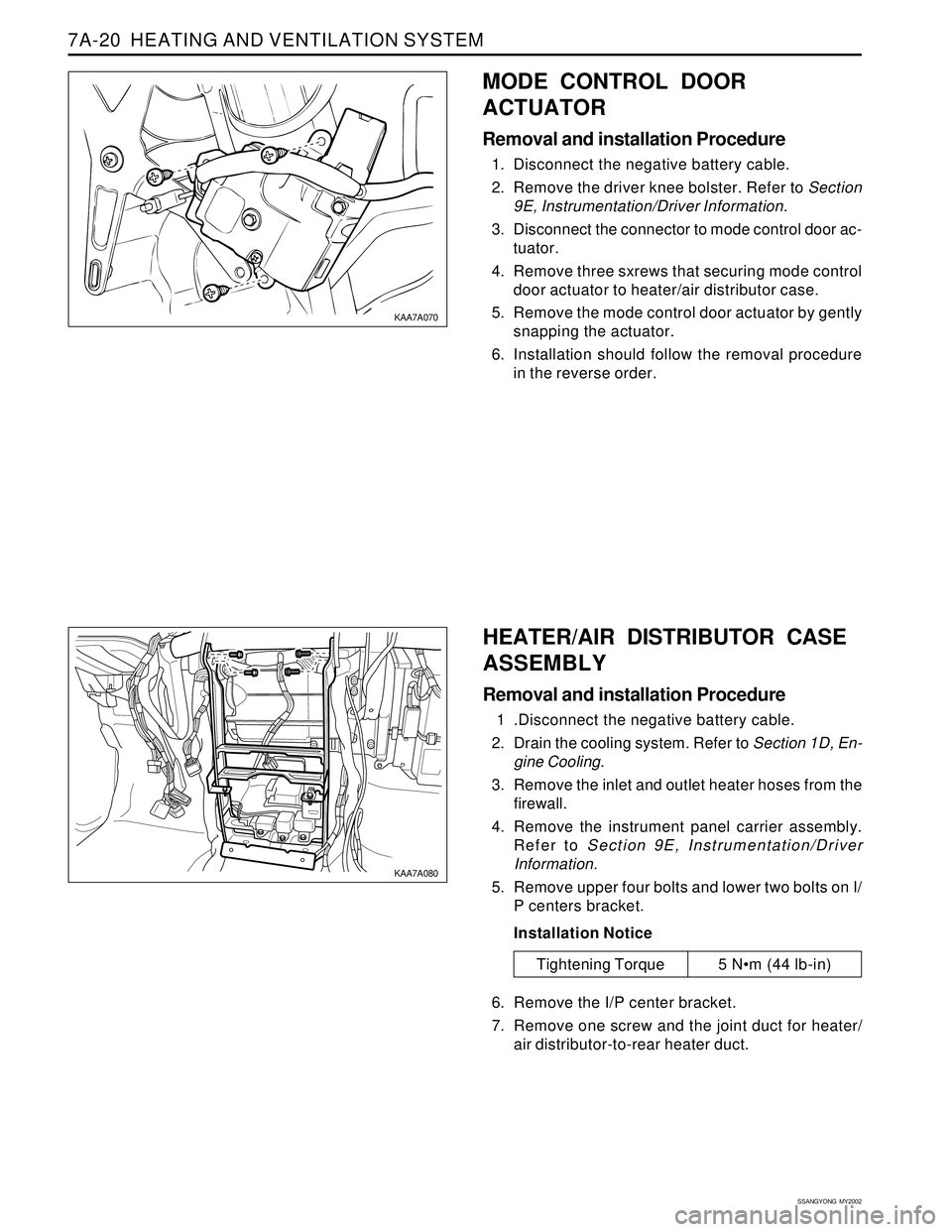
MODE CONTROL DOOR
ACTUATOR
Removal and installation Procedure
1. Disconnect the negative battery cable.
2. Remove the driver knee bolster. Refer to Section
9E, Instrumentation/Driver Information.
3. Disconnect the connector to mode control door ac-
tuator.
4. Remove three sxrews that securing mode control
door actuator to heater/air distributor case.
5. Remove the mode control door actuator by gently
snapping the actuator.
6. Installation should follow the removal procedure
in the reverse order.
Tightening Torque 5 Nm (44 lb-in)
KAA7A070
KAA7A080
HEATER/AIR DISTRIBUTOR CASE
ASSEMBLY
Removal and installation Procedure
1 .Disconnect the negative battery cable.
2. Drain the cooling system. Refer to Section 1D, En-
gine Cooling.
3. Remove the inlet and outlet heater hoses from the
firewall.
4. Remove the instrument panel carrier assembly.
Refer to Section 9E, Instrumentation/Driver
Information.
5. Remove upper four bolts and lower two bolts on I/
P centers bracket.
Installation Notice
6. Remove the I/P center bracket.
7. Remove one screw and the joint duct for heater/
air distributor-to-rear heater duct.
Page 1523 of 2053
SSANGYONG MY2002
7A-22 HEATING AND VENTILATION SYSTEM
7. Installation should follow the removal procedure
in the reverse order.
Installation Notice: After install the blower motor
confirm that the blower motor operates properly.
KAA7A130
KAA7A140
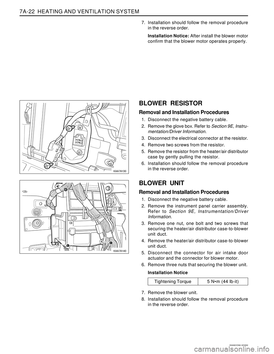
BLOWER RESISTOR
Removal and Installation Procedures
1. Disconnect the negative battery cable.
2. Remove the glove box. Refer to Section 9E, Instru-
mentation/Driver Information.
3. Disconnect the electrical connector at the resistor.
4. Remove two screws from the resistor.
5. Remove the resistor from the heater/air distributor
case by gently pulling the resistor.
6. Installation should follow the removal procedure
in the reverse order.
BLOWER UNIT
Removal and Installation Procedures
1. Disconnect the negative battery cable.
2. Remove the instrument panel carrier assembly.
Refer to Section 9E, Instrumentation/Driver
Information.
3. Remove one nut, one bolt and two screws that
securing the heater/air distributor case-to-blower
unit duct.
4. Remove the heater/air distributor case-to-blower
unit duct.
5. Disconnect the connector for air intake door
actuator and the connector for blower motor.
6. Remove three nuts that securing the blower unit.
Installation Notice
7. Remove the blower unit.
8. Installation should follow the removal procedure
in the reverse order.
Tightening Torque 5 Nm (44 lb-it)
Page 1571 of 2053
FATC-HAVC 7D-17
SSANGYONG MY2002
KAA7D150
KAA7D160
KAA7D170
KAA7D180
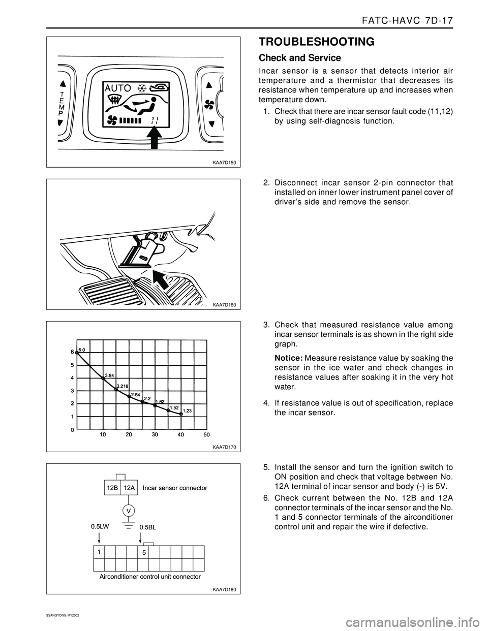
TROUBLESHOOTING
Check and Service
Incar sensor is a sensor that detects interior air
temperature and a thermistor that decreases its
resistance when temperature up and increases when
temperature down.
1. Check that there are incar sensor fault code (11,12)
by using self-diagnosis function.
2. Disconnect incar sensor 2-pin connector that
installed on inner lower instrument panel cover of
driver’s side and remove the sensor.
3. Check that measured resistance value among
incar sensor terminals is as shown in the right side
graph.
Notice: Measure resistance value by soaking the
sensor in the ice water and check changes in
resistance values after soaking it in the very hot
water.
4. If resistance value is out of specification, replace
the incar sensor.
5. Install the sensor and turn the ignition switch to
ON position and check that voltage between No.
12A terminal of incar sensor and body (-) is 5V.
6. Check current between the No. 12B and 12A
connector terminals of the incar sensor and the No.
1 and 5 connector terminals of the airconditioner
control unit and repair the wire if defective.