1997 SSANGYONG KORANDO fuel type
[x] Cancel search: fuel typePage 4 of 2053

0B -- 4 GENERAL INFORMATION
D AEW OO M Y_2000
Tire and Wheel
ApplicationSpecifications
Standard Tire SizeP235/75 R15, 255/70 R15
Standard Wheel Size7JJx15
Inflation Pressure At Full Lode
P235 / 75 : Front
Rear
P255 / 75 : Front
Rear
30 Psi
30 Psi
30 Psi
30 Psi
Steering System
ApplicationSpecifications
Gear TypeRACK & PINION
Wheel Alignment:
Front: Toe -- in
Front: Caster
Front: Camber
0--4mm
2°30′±30′
0°±30′
Oil Capacity1L
Suspension
ApplicationSpecifications
Front TypeDouble Wishbone
Rear Type5--Link
Fuel System
ApplicationSpecifications
Fuel Pump TypeElectric Motor Pump
Fuel Capacity70 L
Lubricating System
Application661LA662NA662LA2.0L
DOHC2.3L
DOCH3.2L
DOCH
Oil Pump TypeExternal Gear pump
Oil Filter TypeCombination (Full & Part)Full Flow
Oil Capacity (L)
(Including Oil Filter)8.09.09.57.27.58.2
Cooling System
Application661LA662NA662LA2.0L
DOHC2.3L
DOCH3.2L
DOCH
Coolant Capacity (L)9.5 -- 1010.510.5 -- 1110.510.511. 3
Radiator TypeForced Circulation
Water Pump TypeCentrifugal
Page 8 of 2053

0B -- 8 GENERAL INFORMATION
D AEW OO M Y_2000
MAINTENANCE AND REPAIR
MAINTENANCE AND
LUBRICATION
NORMAL VEHICLE USE
The maintenance instructions contained in the mainte-
nance schedule are based on the assumption that the
vehicle will be used for the following reasons:
DTo carry passengers and cargo within the limitation of
the tire inflation prassure. Refer to “Tire and Wheel” in
section 2E.
DTo be driven on reasonable road surfaces and within
legal operating limits.
EXPLANATION OF SCHEDULED
MAINTENANCE SERVICES
The services listed in the maintenance schedule are fur-
ther explained below. When the following maintenance
services are performed, make sure all the parts are re-
placed and all the necessary repairs are done before
driving the vehicle. Always use the proper fluid and lubri-
cants.
Engine Oil and Oil Filter Change
Always use above the API SH grade or recommended
engine oil.
Engine Oil Viscosity
Engine oil viscosity (thickness) has an effect on fuel
economy and cold weather operation. Lower viscosity
engine oils can provide better fuel economy and cold
weather performance; however, higher temperature
weather conditions require higher viscosity engine oils
for satisfactory lubrication. Using oils of any viscosity
other than those viscosities recommended could result
in engine damage.
Cooling System Service
Drain, flush and refill the system with new coolant. Refer
to “Recommended Fluids And Lubricants“ in this sec-
tion.
Air Cleaner Element Replacement
Clean the air cleaner element every.
DGasoline Engine : 15,000km (10,000 miles)
DDiesel Engine : 10,000km (6,000 miles)
Replace the air cleaner element every .
DGasoline Engine : 60,000km (36,000 miles)DDiesel Engine : 30,000km (18,000 miles)
Replace the air cleaner more often under dusty condi-
tions.
Fuel Filter Replacement
Replace the engine fuel filter every.
DGasoline Engine : 60,000km (36,000 miles)
DDiesel Engine : 45,000km (24,000 miles)
Spark Plug Replacement
Replace spark plugs with same type.
DType : BOSCH : F8DC4
BERU : 14F-- 8DU4
Champion : C11YCC
DGap : 0.8±0.1 mm
Spark Plug Wire Replacement
Clean wires and inspect them for burns, cracks or other
damage. Check the wire boot fit at the Distributor and at
the spark plugs. Replace the wires as needed.
Brake System Service
Check the disc brake pads or the drum brake linings.
Check the pad and the lining thickness carefully.
Tire and Wheel Inspection and Rotation
Check the tires for abnormal wear or damage. To equal-
ize wear and obtain maximum tire life, rotate the tires. If
irregular or premature wear exists, check the wheel
alignment and check for damaged wheels. While the
tires and wheels are removed, inspect the brakes.
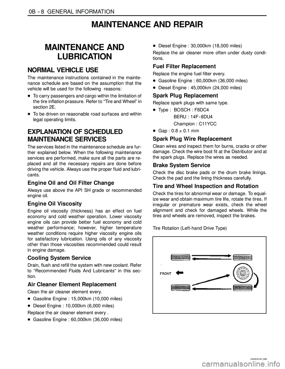
Tire Rotation (Left-hand Drive Type)
Page 15 of 2053

GENERAL INFORMATION 0B -- 15
D AEW OO M Y_2000
RECOMMENDED FLUIDS AND LUBRICANTS
UsageCapacityFluid/Lubricant
Engine Oil
(Change with filter)3.2L DOHC8.2 LQuality class -- API ; SH grade or above
ACEA ; A2 or A3
(Changewithfilter)
2.3L DOHC7.5 L
ACEA;A2orA3
MB sheet ; 229.1
Viscosity -- MB sheet ; 224.1
662LA9.5 LQuality class -- API ; CG grade or above
ACEA ; B2 or B3
MBsheet;22812283661LA8.0 LMBsheet ; 228.1, 228.3,
228.5, 229.1
Viscosity -- MB sheet ; 224.1
Engine Coolant3.2L DOHC11. 3 LALUTEC P-- 78g
2.3L DOHC10.5 L
662LA10.5 -- 11.0 L
661LA9.5 -- 10.0 L
Brake / Clutch FluidApprox. 0.5L level must
be maintained between
MAX&MINlevelDOT -- 3 & SAE J 1703
Power Steering System1.0 LATF DEXRON--II
Parking Brake CableAs requiredGrease
Hood Latch AssemblyAs requiredGrease
Hood and Door Hinges
Fuel Door Hinge
Rear Compartment Lid HingesAs requiredSpray type grease
WeatherstripsAs requiredSilicone grease
Page 22 of 2053

1A1 -- 2 GENERAL ENGINE INFORMATION
D AEW OO M Y_2000
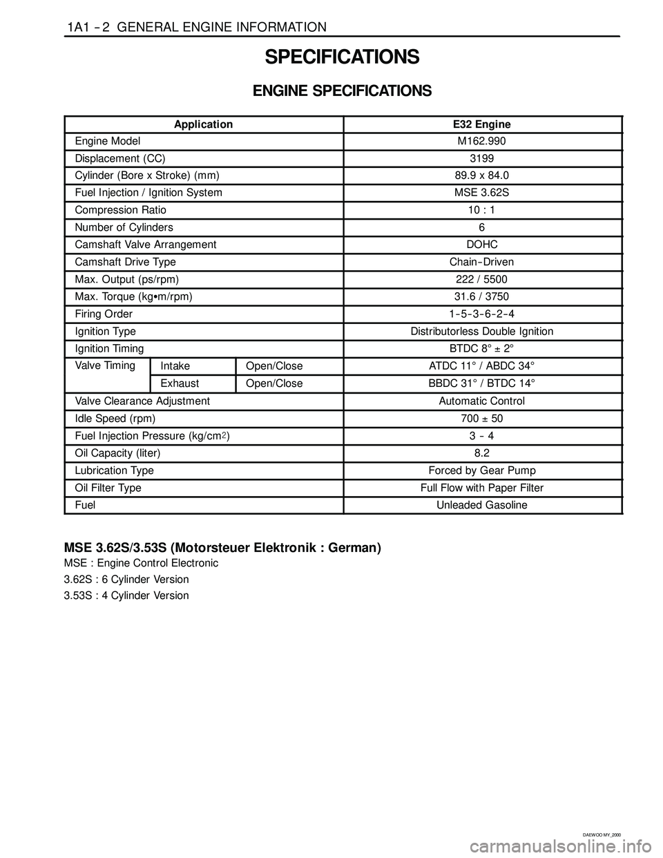
SPECIFICATIONS
ENGINE SPECIFICATIONS
ApplicationE32 Engine
Engine ModelM162.990
Displacement (CC)3199
Cylinder (Bore x Stroke)(mm)89.9 x 84.0
Fuel Injection / Ignition SystemMSE 3.62S
Compression Ratio10 : 1
Number of Cylinders6
Camshaft Valve ArrangementDOHC
Camshaft Drive TypeChain-- Driven
Max. Output (ps/rpm)222 / 5500
Max. Torque (kgSm/rpm)31.6 / 3750
Firing Order1--5--3--6--2--4
Ignition TypeDistributorless Double Ignition
Ignition TimingBTDC 8°±2°
Valve TimingIntakeOpen/CloseAT DC 11°/ ABDC 34°g
ExhaustOpen/CloseBBDC 31°/BTDC14°
Valve Clearance AdjustmentAutomatic Control
Idle Speed (rpm)700±50
Fuel Injection Pressure (kg/cm@)3--4
Oil Capacity (liter)8.2
Lubrication TypeForced by Gear Pump
Oil Filter TypeFull Flow with Paper Filter
FuelUnleaded Gasoline
MSE 3.62S/3.53S (Motorsteuer Elektronik : German)
MSE : Engine Control Electronic
3.62S : 6 Cylinder Version
3.53S : 4 Cylinder Version
Page 168 of 2053

M162 ENGINE CONTROLS 1F1 -- 5
D AEW OO M Y_2000
FUEL SYSTEM SPECIFICATION
Use Only Unleaded Fuel Rated at 89
Octane or Higher
Fuel quality and additives contained in fuel have a s ig n if i-
cant effect on power output, drivability, and life of the en-
gine.
Fuel with too low an octane number can cause engine
knock.
Caution: Use of fuel with an octane number lower
than 89 may damage engine and exhaust system.
Notice:To prevent accidental use of leaded fuel, the
nozzles for leaded fuel are larger, andwill not fit the fuel
filler neck of your vehicle.
Do Not Use Methanol
Fuels containing methanol (wood alcohol) should not be
used in vehicle.This type of fuel can reduce vehicle performance and
damage components of the fuel system.
Caution: Use of methanol may damage the fuel sys -
tem.
Vehicle Fueling from Drums or Storage
Containers
For safety reasons (particularly when using noncom-
mercial fueling systems) fuel containers, pumps and
hoses must be properly earthed.
Static electricity build up can occur under certain atmo-
spheric and fuel flow conditions if unearthed hoses, par-
ticularly plastic, are fitted to the fuel-- dispensing pump.
It is therefore recommended that earthed pumps with in-
tegrally earthed hoses be used, and that storage con-
tainers be properly earthed during all noncommercial
fueling operations.
TEMPERATURE VS RESISTANCE
°C°FECT sensorIAT sensor°C°FOHMS (Ω)
Temperature vs Resistance Values (Approximate)
13026688102
120248111. 6127
110230143159
100212202202
90194261261
80176340340
70158452452
60140609609
50122835835
40113116 61166
308616621662
206824202420
105036043604
03254995499
-- 1 01486098609
-- 2 0-- 41385013850
-- 3 0-- 2 22296022960
-- 4 0-- 4 03926039260
Page 177 of 2053

1F1 -- 14 M162 ENGINE CONTROLS
D AEW OO M Y_2000
DIAGNOSIS
FAILURE CODE DIAGNOSIS
CLEARING FAILURE CODES
Notice:To prevent Engine Control Module (ECM) damage, the key must be OFF when disconnecting or reconnecting
the power to the ECM (for example battery cable, ECM pigtail connector, ECM fuse, jumper cables, etc.)
Parameters listed in the table may not be exactly the same as your reading due to the type of instrument or other
factors. If a failure code is displayed during the “TROUBLE CODE” in scan tool check mode, check the circuit for the
code listed in the table below. For details of each code, turn to the page referred to under the “See Page” for the re-
spective “Failure Code” in the below table.
Failure codes should be cleared after repairs have been completed.
FAILURE CODES TABLE
Failure
codeSee
PageDescription
001F1 -- 66Engine coolant temperature sensor low voltage
011F1 -- 66Engine coolant temperature sensor high voltage
021F1 -- 66Engine coolant temperature sensor plausibility
031F1 -- 62Intake air temperature sensor low voltage
041F1 -- 62Intake air temperature sensor high voltage
051F1 -- 62Intake air temperature sensor plausibility
061F1 -- 66Engine coolant temperature insufficient for closed loop fuel control
081F1 -- 38System voltage too low
091F1 -- 62Mass air flow sensor plausibility
101F1 -- 62Mass air flow sensor low voltage
111F1 -- 62Mass air flow sensor high voltage
171F1 -- 23Crankshaft position sensor signal failure (no engine revolution signal)
181F1 -- 23Crankshaft position sensor signal failure (rpm > max. value)
191F1 -- 27Camshaft position senosr signal : No.1 cylinder recognition failure
201F1 -- 23Crankshaft position sensor signal failure (gap recognition failure)
211F1 -- 90Transmission coding failure
231F1 -- 88CAN communication failure : ASR/MSR
241F1 -- 88CAN communication failure : ABS
251F1 -- 94Communication with transponder missing
261F1 -- 88CAN communication failure : TCU (A/T only)
271F1 -- 88CAN communication failure : TOD (E32 only)
291F1 -- 89CAN communication failure : ID 200h not plausible
301F1 -- 89CAN communication failure : ID 208h not plausible
311F1 -- 89CAN communication failure : communication initialization failure
321F1 -- 78Engine rpm output circuit short circuit to battery
331F1 -- 78Engine rpm output circuit short circuit to ground or open
341F1 -- 43Fuel pump relay short circuit to battery
351F1 -- 43Fuel pump relay short circuit to ground or open
Page 185 of 2053

1F1 -- 22 M162 ENGINE CONTROLS
D AEW OO M Y_2000
CRANKSHAFT POSITION (CKP) SENSOR
YAA1F250
This Electronic Ignition (EI) system uses inductive or pickup type magnetic Crankshaft Position (CKP) sensor. The
CKP sensor is located in the opposite side of the crankshaft pulley and triggers the pick-up wheel teeth which is
equipped 60 -- 2 teeth with a gap of 2 teeth at 360 degree spacing. This sensor protrudes through its mount to within 1.1
±0.14 mm.
The output of the sensor is a sinusoidal signal. Each tooth of the pick-up 60 -- 2 wheel generates a positive half wave.
The Engine Control Module (ECM) uses this sensor signal to generate timed ignition and injection pulses that it sends
to the ignition coils and to the fuel injectors.
Page 263 of 2053

1F1 -- 100 M162 ENGINE CONTROLS
D AEW OO M Y_2000
KAA1F090
Notice:Before removal, the fuel rail assembly may be
cleaned with a spray-type cleaner, following package in-
structions. Do not immerse the fuel rails in liquid clean-
ing solvent. Use care in removing the fuel rail assembly
to prevent damage to the electrical connectors and in-
jector spray tips. Prevent dirt and other contaminants
from entering open lines and passages. Fittings should
be capped and holes plugged during service.
Important:If an injector becomes separated from the
rail and remains in the cylinder head, replace the injector
O-ring seals and the retaining clip.
12. Remove the injectors and the fuel rail carefully.
13. Remove the fuel injector retainer clips.
14. Remove the fuel injectors by pulling them down and
out.
15. Discard the fuel injector O-rings.
16. Lubricate the new fuel injector O-rings with engine
oil. Install the new O-rings on the fuel injectors.
17. Perform a leak check of the fuel rail and fuel injec-
tors.
18. Installation should follow the removal procedure in
the reverse order.
YAA1F150
ENGINE COOLANT TEMPERATURE
SENSOR
Removal and Installation Procedure
1. Relieve the coolant system pressure.
2. Disconnect the negative battery cable.
3. Disconnect the engine coolant temperature sensor
connector.
Notice:Take care when handling the engine coolant
temperature sensor. Damage to the sensor will affect
the proper operation of the fuel injection system.
4. Remove the engine coolant temperature sensor
from the pump hosing.
Installation Notice
Tightening Torque
30 NSm (22 Ib-ft)
5. Installation should follow the removal procedure in
the reverse order.