1997 SSANGYONG KORANDO lights
[x] Cancel search: lightsPage 13 of 2053

GENERAL INFORMATION 0B -- 13
D AEW OO M Y_2000
OWNER INSPECTIONS AND SERVICES
WHILE OPERATING THE VEHICLE
Horn Operation
Blow the horn occasionally to make sure it works. Check
all the button locations.
Brake System Operation
Be alert for abnormal sounds, increased brake pedal
travel or repeated puling to one side when braking. Also,
if the brake warning light goes on, or flashes, something
may be wrong with part of the brake system.
Exhaust System Operation
Be alert to any changes inthe sound of the system or
the smell of the fumes. These are signs that the system
may be leaking or overheating. Have the system in-
spected and repaired immediately.
Tires, Wheels and Alignment Operation
Be alert to any vibration of the steering wheel or the
seats at normal highway speeds. This may mean a
wheel needs to be balanced. Also, a pull right or left on a
straight, level road may show the need for a tire pres-
sure adjustment or a wheel alignment.
Steering System Operation
Be alert to changes in the steering action. An inspection
is needed when the steering wheel is hard to turn or has
too much free play, or is unusual sounds are noticed
when turning or parking.
Headlight Aim
Take note of the light pattern occasionally. Adjust the
headlights if the beams seem improperly aimed.
AT EACH FUEL FILL
A fluid loss in any (except windshield washer) system
may indicate a problem. Have the system inspected and
repaired immediately.
Engine Oil Level
Check the oil level and add oil if necessary. The best
time to check the engine oil level is when the oil is warm.
1. After stopping the engine, wait a few minutes for the
oil to drain back to the oil pan.
2. Pull out the oil level indicator (dip stick).
3. Wipe it clean, and push the oil level indicator back
down all the way.
4. Pull out the oil level indicator and look at the oil level
on it.
5. Add oil, if needed, to keep the oil level above the low-
er mark. Avoid overfilling theengine, since this may
cause engine damage.
6. Push the indicator all the way back down into the en-
gine after taking the reading.If you check the oil level when the oil is cold, do not run
the engine first. The cold oil will not drain back to the pan
fast enough to give a true oil level reading.
Engine Coolant Level and Condition
Check the coolant level in the coolant reservoir tank and
add coolant if necessary. Inspect the coolant. Replace
dirty or rusty coolant.
Windshield Washer Fluid Level
Check the washer fluid level in the reservoir. Add fluid if
necessary.
AT LEAST TWICE A MONTH
Tire And Wheel Inspection and Pressure
Check
Check the tire for abnormal wear or damage. Also check
for damaged wheels. Check the tire pressure when the
tires are cold ( check the spare also, unless it is a stow-
away). Maintain the recommended pressures. Refer to
“Tire and Wheel” is in section 0B.
AT LEAST MONTHLY
Light Operation
Check the operation of the license plate light, the head-
lights (including the high beams), the parking lights, the
fog lights, the taillight, the brake lights, the turn signals,
the backup lights and the hazard warning flasher.
Fluid Leak Check
Periodically inspect the surface beneath the vehicle for
water, oil, fuel or other fluids, after the vehicle has been
parked for a while. Water dripping from the air condition-
ing system after use is normal. If you notice fuel leaks or
fumes, find the cause and correct it at once.
AT LEAST TWICE A YEAR
Power Steering System Reservoir Level
Check the power steering fluid level. Keep the power
steering fluid at the proper level. Refer to Section 6A,
Power Steering System.
Brake Master Cylinder Reservoir Level
Check the fluid and keep it at the proper level. A low fluid
level can indicate worn disc brake pads which may need
to be serviced. Check the breather hole in the reservoir
cover to be free from dirt and check for an open pas-
sage.
Weather- Strip Lubrication
Apply a thin film silicone grease using a clean cloth.
Page 794 of 2053

OM600 ENGINE CONTROLS 1F3 -- 37
D AEW OO M Y_2000
Tools Required
617 589 08 21 00 Position Sensor
Test Procedure
1. Remove the screw plug (5) and seal (4) and collect
oil in a suitable vessel.
2. Install the position sensor (1) into the governor
housing of the injection pump to be the guide pin of
the position sensor facing up.
3. Connect the battery terminal of position sensor (1)
to positive terminal (+) of battery.
Position Sensor 617 589 08 21 00
4. Rotate the crankshaft by hand (in direction of engine
rotation) until the lamp ’B’ lights up. Rotate the
crankshaft carefully further until both lamps ’A and
B’ come on. In this position, check the Rl value on
the crankshaft vibration damper.
SpecificationAT DC 1 4_-- 1 6_
Notice
If only lamp ’A’ lights up, repeat the test and if out of
specification, adjust start of delivery.
Page 1063 of 2053
SSANGYONG MY2002
4F-80 ABS AND TCS
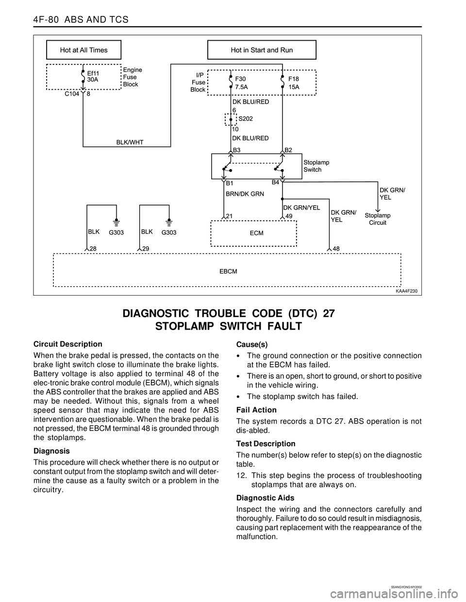
DIAGNOSTIC TROUBLE CODE (DTC) 27
STOPLAMP SWITCH FAULT
KAA4F230
Circuit Description
When the brake pedal is pressed, the contacts on the
brake light switch close to illuminate the brake lights.
Battery voltage is also applied to terminal 48 of the
elec-tronic brake control module (EBCM), which signals
the ABS controller that the brakes are applied and ABS
may be needed. Without this, signals from a wheel
speed sensor that may indicate the need for ABS
intervention are questionable. When the brake pedal is
not pressed, the EBCM terminal 48 is grounded through
the stoplamps.
Diagnosis
This procedure will check whether there is no output or
constant output from the stoplamp switch and will deter-
mine the cause as a faulty switch or a problem in the
circuitry.Cause(s)
The ground connection or the positive connection
at the EBCM has failed.
There is an open, short to ground, or short to positive
in the vehicle wiring.
The stoplamp switch has failed.
Fail Action
The system records a DTC 27. ABS operation is not
dis-abled.
Test Description
The number(s) below refer to step(s) on the diagnostic
table.
12. This step begins the process of troubleshooting
stoplamps that are always on.
Diagnostic Aids
Inspect the wiring and the connectors carefully and
thoroughly. Failure to do so could result in misdiagnosis,
causing part replacement with the reappearance of the
malfunction.
Page 1411 of 2053
TRANSFER CASE (PART TIME - 4408) 5D2-11
SSANGYONG MY2002
KAA5D080
KAA5D090
KAA5D100
SELF-DIAGNOSIS TEST
System Description
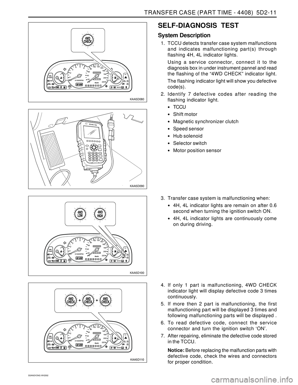
1. TCCU detects transfer case system malfunctions
and indicates malfunctioning part(s) through
flashing 4H, 4L indicator lights.
Using a service connector, connect it to the
diagnosis box in under instrument pannel and read
the flashing of the “4WD CHECK” indicator light.
The flashing indicator light will show you defective
code(s).
2. Identify 7 defective codes after reading the
flashing indicator light.
TCCU
Shift motor
Magnetic synchronizer clutch
Speed sensor
Hub solenoid
Selector switch
Motor position sensor
KAA5D110
3. Transfer case system is malfunctioning when:
4H, 4L indicator lights are remain on after 0.6
second when turning the ignition switch ON.
4H, 4L indicator lights are continuously come
on during driving.
4. If only 1 part is malfunctioning, 4WD CHECK
indicator light will display defective code 3 times
continuously.
5. If more then 2 part is malfunctioning, the first
malfunctioning part will be displayed 3 times and
following malfunctioning parts will be displayed .
6. To read defective code, connect the service
connector and turn the ignition switch ‘ON’.
7. After repairing, eliminate the defective code stored
in the TCCU.
Notice: Before replacing the malfunction parts with
defective code, check the wires and connectors
for proper condition.
Page 1420 of 2053
TRANSFER CASE (PART TIME - 4408) 5D2-21
SSANGYONG MY2002
KAA5D240
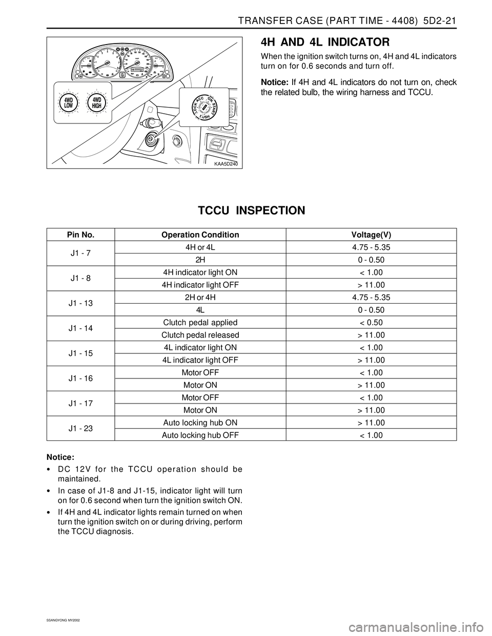
4H AND 4L INDICATOR
When the ignition switch turns on, 4H and 4L indicators
turn on for 0.6 seconds and turn off.
Notice: If 4H and 4L indicators do not turn on, check
the related bulb, the wiring harness and TCCU.
J1 - 7
J1 - 8
J1 - 13
J1 - 14
J1 - 15
J1 - 16
J1 - 17
J1 - 234H or 4L
2H
4H indicator light ON
4H indicator light OFF
2H or 4H
4L
Clutch pedal applied
Clutch pedal released
4L indicator light ON
4L indicator light OFF
Motor OFF
Motor ON
Motor OFF
Motor ON
Auto locking hub ON
Auto locking hub OFF
TCCU INSPECTION
4.75 - 5.35
0 - 0.50
< 1.00
> 11.00
4.75 - 5.35
0 - 0.50
< 0.50
> 11.00
< 1.00
> 11.00
< 1.00
> 11.00
< 1.00
> 11.00
> 11.00
< 1.00
Pin No. Voltage(V)Operation Condition
Notice:
DC 12V for the TCCU operation should be
maintained.
In case of J1-8 and J1-15, indicator light will turn
on for 0.6 second when turn the ignition switch ON.
If 4H and 4L indicator lights remain turned on when
turn the ignition switch on or during driving, perform
the TCCU diagnosis.
Page 1493 of 2053
POWER STEERING AND COLUMN 6E-7
SSANGYONG MY2002
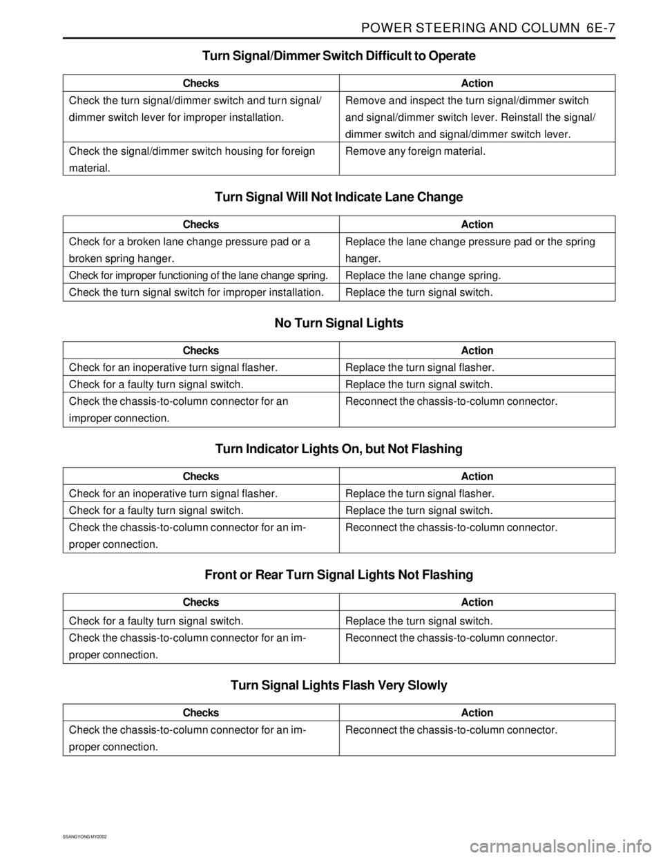
Check the turn signal/dimmer switch and turn signal/
dimmer switch lever for improper installation.
Check the signal/dimmer switch housing for foreign
material.ChecksActionRemove and inspect the turn signal/dimmer switch
and signal/dimmer switch lever. Reinstall the signal/
dimmer switch and signal/dimmer switch lever.
Remove any foreign material.
Turn Signal Will Not Indicate Lane Change
No Turn Signal Lights
Check for an inoperative turn signal flasher.
Check for a faulty turn signal switch.
Check the chassis-to-column connector for an
improper connection.ChecksActionReplace the turn signal flasher.
Replace the turn signal switch.
Reconnect the chassis-to-column connector.
Turn Signal/Dimmer Switch Difficult to Operate
Check for a broken lane change pressure pad or a
broken spring hanger.
Check for improper functioning of the lane change spring.
Check the turn signal switch for improper installation.ChecksActionReplace the lane change pressure pad or the spring
hanger.
Replace the lane change spring.
Replace the turn signal switch.
Turn Indicator Lights On, but Not Flashing
Check for a faulty turn signal switch.
Check the chassis-to-column connector for an im-
proper connection.ChecksActionReplace the turn signal switch.
Reconnect the chassis-to-column connector.
Front or Rear Turn Signal Lights Not Flashing
Turn Signal Lights Flash Very Slowly
Check the chassis-to-column connector for an im-
proper connection.ChecksActionReconnect the chassis-to-column connector.
Check for an inoperative turn signal flasher.
Check for a faulty turn signal switch.
Check the chassis-to-column connector for an im-
proper connection.ChecksActionReplace the turn signal flasher.
Replace the turn signal switch.
Reconnect the chassis-to-column connector.
Page 1574 of 2053
SSANGYONG MY2002
7D-20 FATC-HAVC
KAA7D270
KAA7D280
KAA7D290
KAA7D300
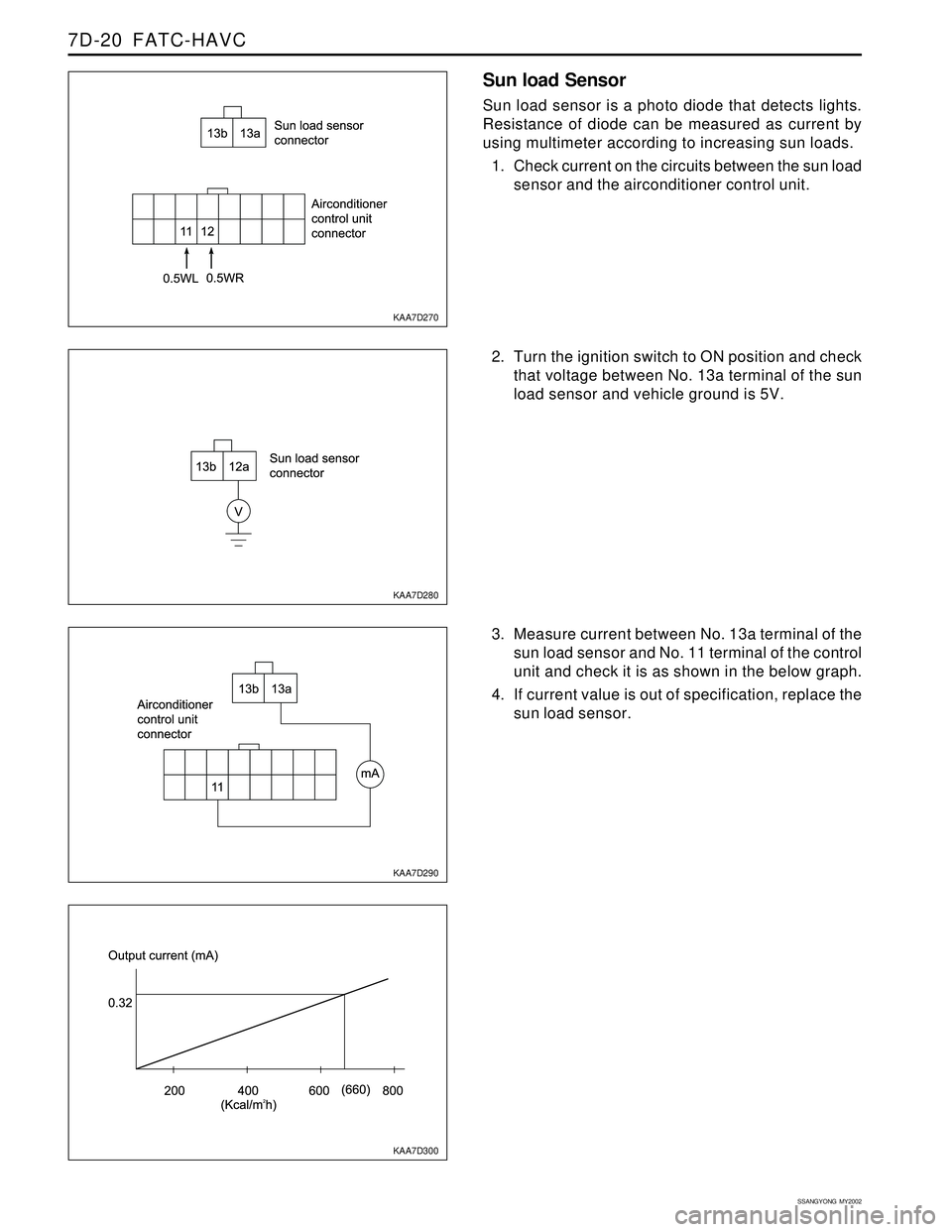
Sun load Sensor
Sun load sensor is a photo diode that detects lights.
Resistance of diode can be measured as current by
using multimeter according to increasing sun loads.
1. Check current on the circuits between the sun load
sensor and the airconditioner control unit.
2. Turn the ignition switch to ON position and check
that voltage between No. 13a terminal of the sun
load sensor and vehicle ground is 5V.
3. Measure current between No. 13a terminal of the
sun load sensor and No. 11 terminal of the control
unit and check it is as shown in the below graph.
4. If current value is out of specification, replace the
sun load sensor.
Page 1719 of 2053

SSANGYONG MY2002
9E-2 INSTRUMENTATION, DRIVER INFORMATION
DESCRIPTION AND OPERATION
CIGAR LIGHTER
The cigar lighter is located in the front portion of the
floor console. To use the lighter, push it in completely.
When the lighter is hot, it will release itsef from contact
with the heating element. The lighter and the heating
element can be damaged if the lighter does not fully
release itsef from the heating element.
ASHTRAY
The ashtray is located in the console. To access the
ashtray, pullit out of the ashtray housing. The ashtray
lamp will go on when the parking lamps or headlamps
are turned on.
INSTRUMENT PANEL VENTS
The center and the side vents in the instrument panel
can be adjusted up and down and from side to side.
The side vents can also be aimed toward the side
windows to defog them.
GLOVE BOX
The glove box can be opened by pulling upon the latch
handle.
DIGITAL CLOCK
The digital clock is located in the instrument cluster.
INSTRUMENT CLUSTER
The instrument cluster is located above the steering
column and in the instrument cluster trim panel. The
instrument cluster contains the instruments that
provide the driver with vehicle performance information.
The instrument cluster contains a speedometer, a
tachometer, an odometer, a trip odometer, a
temperature gauge, a fuel gauge, and several indicator
lamps. For replacement of the indicator lamp bulbs
contained in the instrument cluster, refer to “Instrument
Cluster Indicator Lamps Specifications” in the section.
SPEEDOMETER AND
TACHOMETER
The speedometer measures the speed of the vehicle
in km/h (with mph) or mph (with km/h). It consists of
an instrument cluster gauge connected to the vehicle
speed sensor on the transaxle output shaft. The
tachometer measures the engine’s speed in terms of
thousands of revolutions per minute. It consists of an
instrument cluster gauge connected to a sending unit
in the engine con-trol module. Do not operate the
engine in the red zone. Engine damage may occur.
TRIP ODOMETER
The trip odometer measures the distance the vehicle
has traveled since it was last reset. It consists of an
instrument cluster gauge connected to the sending unit
on the tasnsaxle output shaft. The trip oddometer can
be record the distance traveled from any starting point.
FUEL GAUGE
The fuel gauge consists of an instrument cluster gauge
connected to a sending unit in the fuel tank. The fuel
gauge indicates the quantity of fuel in the tank only
when the ignition is turned to ON or ACC. When the
ignition is turned to LOCK or START, the pointer may
come to rest at any position.
TEMPERATURE GAUGE
The temperature gauge consists of an instrument
cluster gauge connected to a temperature sensor that
is in con-tact with the circulating engine coolant. The
temperature gauge indicates the temperature of the
coolant. Prolonged driving or idling in very hot weather
may cause the pointer to move beyond the center of
the gauge. The engine is overheating if the pointer
moves into the red zone at the upper limit of the gauge.
INSTRUMENT CLUSTER
INDICATOR LAMPS
The instrument cluster contains indicator lamps that
indicatethe functioning of certain systems or the
existenceof potential problems with the operation of
the vehicle. The indicator lamps are replaceable. For
replacement of the indicator lamps contained in the
instrument cluster, refer to “instrument cluster indicator
lamps specifications” in this section.
CHIME MODULE
The chime module will sound to bring attention to one
or more of the following conditions:
The lights are on and the ignition not in ACC, ON,
or START.
The ignition key is in the ignition switch when the
driver’s side door is open.
The seat belt is unbuckled when the ignition is in
ACC, ON, or START.
Voltage is supplied at all times through the fuse block
to power the chime module.