1997 SSANGYONG KORANDO immobilizer
[x] Cancel search: immobilizerPage 164 of 2053

D AEW OO M Y_2000
SECTION 1F1
ENGINE CONTROLS
CAUTION: Disconnect the negative battery cable before removing or installing any electrical unit or when a
tool or equipment could easily come in contact with exposed electrical terminals. Disconnecting this cable
will help prevent personal injury and damage to the vehicle. The ignition must also be in LOCK unless other -
wise noted.
TABLE OF CONTENTS
Engine and ECM Problem Check Report 1F1 -- 2....
Specifications 1F1 -- 3............................
Engine Data Display Table 1F1 -- 3.................
Fastener Tightening Specifications 1F1 -- 4..........
Fuel System Specification 1F1 -- 5.................
Temperature vs Resistance 1F1 -- 5................
Special Tools and Equipment 1F1 -- 6..............
Special Tools Table 1F1 -- 6.......................
Schematic and Routing Diagrams 1F1 -- 7..........
ECM Wiring Diagram
(3.2L DOHC -- MSE 3.62S) 1F1 -- 7..............
Diagnosis 1F1 -- 14................................
Failure Code Diagnosis 1F1 -- 14.....................
Clearing Failure Codes 1F1 -- 14...................
Failure Codes Table 1F1 -- 14.....................
Ignition System 1F1 -- 18...........................
Ignition Coil 1F1 -- 20.............................
Crankshaft Position (CKP) Sensor 1F1 -- 22.........
Camshaft Position (CMP) Sensor 1F1 -- 26..........
Camshaft Actuator 1F1 -- 30......................
Knock Sensor (KS) 1F1 -- 32......................
Spark Plug 1F1 -- 34.............................
System Voltage 1F1 -- 38.........................
Ignition Switch 1F1 -- 39..........................
Fuel System 1F1 -- 40..............................
Fuel Pump 1F1 -- 42.............................
Fuel Injector 1F1 -- 46............................
Purge Control Valve 1F1 -- 50.....................
Fuel Rail 1F1 -- 52...............................
Fuel Pressure Regulator 1F1 -- 54.................
Induction System 1F1 -- 56..........................
Throttle Valve Actuator 1F1 -- 56...................
Hot Film Air Mass (HFM) Sensor 1F1 -- 60..........
Engine Coolant Temperature (ECT) Sensor 1F1 -- 64.
Accelerator Pedal Module 1F1 -- 68................
Clutch Switch 1F1 -- 71...........................Cooling Fan 1F1 -- 72............................
A/C Compressor Relay 1F1 -- 73...................
Cruise Control Switch 1F1 -- 74....................
Traction Control System (TCS) 1F1 -- 75............
Resonance Flap 1F1 -- 76.........................
Stop Lamp Switch 1F1 -- 77.......................
Engine RPM 1F1 -- 78............................
Exhaust System 1F1 -- 79...........................
Catalytic Converter 1F1 -- 79......................
Oxygen Sensor 1F1 -- 80.........................
Engine Control Module 1F1 -- 86.....................
Serial Data Communication 1F1--88...............
Internal Failure 1F1 -- 90..........................
Electronic Throttle Controller Safety
Malfunction 1F1 -- 92...........................
Immobilizer 1F1 -- 94.............................
Maintenance and Repair 1F1 -- 95..................
On -- Vehicle Service 1F1 -- 95........................
Discharging the Pressure in Fuel System 1F1 -- 95...
Fuel Pump 1F1 -- 95.............................
Fuel Filter 1F1 -- 96..............................
Fuel Tank 1F1 -- 97..............................
Fuel Pressure Regulator 1F1 -- 98.................
Fuel Rail and Injector 1F1 -- 99....................
Engine Coolant Temperature Sensor 1F1 -- 100......
Throttle Body (Integrated with the
Actuator) 1F1 -- 101............................
Hot Film Air Mass (HFM) Sensor 1F1 -- 102.........
Knock Sensor 1F1 -- 102..........................
Pedal Position Sensor 1F1 -- 103...................
Oxygen Sensor 1F1 -- 103........................
Purge Control Valve 1F1 -- 104....................
Canister 1F1 -- 104...............................
Camshaft Position Sensor 1F1 -- 104...............
Crankshaft Position Sensor 1F1 -- 105..............
Engine Control Module 1F1 -- 105..................
Page 179 of 2053

1F1 -- 16 M162 ENGINE CONTROLS
D AEW OO M Y_2000
FAILURE CODES TABLE (Cont’d)
Failure
codeSee
PageDescription
1031F1 -- 83Bank 1 system learning control failure (lean, high load)
1041F1 -- 57Throttle position sensor 1 low voltage
1051F1 -- 57Throttle position sensor 1 high voltage
1081F1 -- 57Throttle position sensor 2 low voltage
1091F1 -- 57Throttle position sensor 2 high voltage
1101F1 -- 92Throttle actuator learning data fault
1161F1 -- 57Throttle actuator learning control failure
1171F1 -- 92Exceed fuel-- cut safety time
1191F1 -- 57Throttle valve return spring failure
1201F1 -- 92Cruise control interruption memory failure
1211F1 -- 57Throttle actuator failure
1221F1 -- 69Accelerator pedal position sensor signal failure
1231F1 -- 57Different Mass air flow sensor signal with throttle position sensor
1251F1 -- 57Both throttle position sensors failure
1261F1 -- 58Throttle position sensor 1 not plausible with throttle position sensor 2
1271F1 -- 58High permanent throttle signal
1291F1 -- 74Cruise control “OFF” due to message counter failure
1301F1 -- 74Vehicle speed signal failure
1311F1 -- 74Vehicle speed signal failure
1321F1 -- 74Cruise control lever failure
1331F1 -- 74Cruise control acceleration failure
1341F1 -- 74Cruise control deceleration failure
1351F1 -- 77Stop lamp switch failure
1361F1 -- 90ECU failure (RAM)
1371F1 -- 90ECU failure (EPROM)
1381F1 -- 92Call monitoring
1391F1 -- 92Servo motor control output interruption memory failure
1401F1 -- 92Servo motor open/short
1411F1 -- 94Unprogramed ECU with immobilizer
1421F1 -- 90Uncoded/unprogramed ECU
1431F1 -- 90ECU failure (EEPROM/Flash -- EPROM checksum failure)
1441F1 -- 90ECU failure (coding ID checksum failure)
1451F1 -- 90ECU failure (coding checksum failure)
1461F1 -- 90ECU failure (programing checksum failure)
1501F1 -- 75TCS input signal short circuit to battery
1511F1 -- 75TCS input signal short circuit to ground or open
1601F1 -- 69Accelerator pedal position sensor 1 low voltage
1611F1 -- 69Accelerator pedal position sensor 1 high voltage
1621F1 -- 69Accelerator pedal position sensor 2 low voltage
1631F1 -- 69Accelerator pedal position sensor 2 high voltage
1641F1 -- 69Accelerator pedal position sensor 1 not plausible with pedal position sensor 2
Page 257 of 2053

1F1 -- 94 M162 ENGINE CONTROLS
D AEW OO M Y_2000
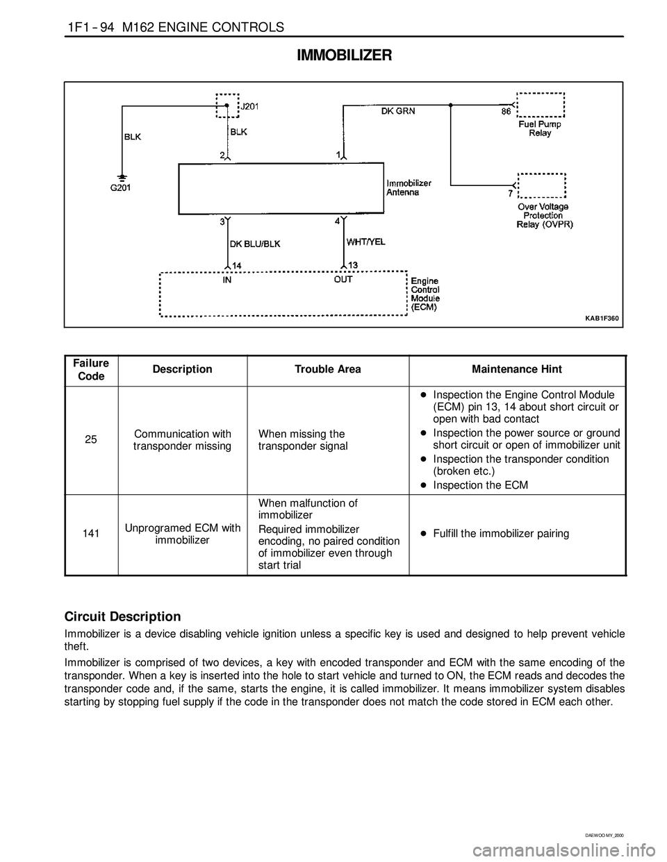
IMMOBILIZER
KAB1F360
Failure
CodeDescriptionTrouble AreaMaintenance Hint
25Communication with
transponder missingWhen missing the
transponder signal
DInspection the Engine Control Module
(ECM) pin 13, 14 about short circuit or
open with bad contact
DInspection the power source or ground
short circuit or open of immobilizer unit
DInspection the transponder condition
(broken etc.)
DInspection the ECM
141Unprogramed ECM with
immobilizer
When malfunction of
immobilizer
Required immobilizer
encoding, no paired condition
of immobilizer even through
start trial
DFulfill the immobilizer pairing
Circuit Description
Immobilizer is a device disabling vehicle ignition unless a specific key is used and designed to help prevent vehicle
theft.
Immobilizer is comprised of two devices, a key with encoded transponder and ECM with the same encoding of the
transponder. When a key is inserted into the hole to start vehicle and turned to ON, the ECM reads and decodes the
transponder code and, if the same, starts the engine, it is called immobilizer. It means immobilizersystem disables
starting by stopping fuel supply if the code in the transponder does not match the code stored in ECM each other.
Page 423 of 2053

D AEW OO M Y_2000
SECTION 1F2
ENGINE CONTROLS
CAUTION: Disconnect the negative battery cable before removing or installing any electrical unit or when a
tool or equipment could easily come in contact with exposed electrical terminals. Disconnecting this cable
will help prevent personal injury and damage to the vehicle. The ignition must also be in LOCK unless other -
wise noted.
TABLE OF CONTENTS
Engine and ECM Problem Check Report 1F2 -- 2....
Specifications 1F2 -- 3............................
Engine Data Display Table 1F2 -- 3.................
Fastener Tightening Specifications 1F2 -- 4..........
Fuel System Specification 1F2 -- 5.................
Temperature vs Resistance 1F2 -- 5................
Special Tools and Equipment 1F2 -- 6..............
Special Tools Table 1F2 -- 6.......................
Schematic and Routing Diagrams 1F2 -- 7..........
ECM Wiring Diagram
(2.3L DOHC -- MSE 3.53S) 1F2 -- 7..............
Diagnosis 1F2 -- 14................................
Failure Code Diagnosis 1F2 -- 14.....................
Clearing Failure Codes 1F2 -- 14...................
Failure Codes Table 1F2 -- 14.....................
Ignition System 1F2 -- 18...........................
Ignition Coil 1F2 -- 20.............................
Crankshaft Position (CKP) Sensor 1F2 -- 22.........
Camshaft Position (CMP) Sensor 1F2 -- 26..........
Camshaft Actuator 1F2 -- 30......................
Knock Sensor (KS) 1F2 -- 32......................
Spark Plug 1F2 -- 34.............................
System Voltage 1F2 -- 38.........................
Ignition Switch 1F2 -- 39..........................
Fuel System 1F2 -- 40..............................
Fuel Pump 1F2 -- 42.............................
Fuel Injector 1F2 -- 46............................
Purge Control Valve 1F2 -- 50.....................
Fuel Rail 1F2 -- 52...............................
Fuel Pressure Regulator 1F2 -- 54.................
Induction System 1F2 -- 56..........................
Throttle Valve Actuator 1F2 -- 56...................
Hot Film Air Mass (HFM) Sensor 1F2 -- 60..........
Engine Coolant Temperature (ECT) Sensor 1F2 -- 64.
Accelerator Pedal Module 1F2 -- 68................Cooling Fan 1F2 -- 72............................
A/C Compressor Relay 1F2 -- 73...................
Cruise Control Switch 1F2 -- 74....................
Traction Control System (TCS) 1F2 -- 75............
Stop Lamp Switch 1F2 -- 76.......................
Engine RPM 1F2 -- 77............................
Exhaust System 1F2 -- 78...........................
Catalytic Converter 1F2 -- 78......................
Oxygen Sensor 1F2 -- 80.........................
Engine Control Module 1F2 -- 86.....................
Serial Data Communication 1F2--88...............
Internal Failure 1F2 -- 90..........................
Electronic Throttle Controller Safety
Malfunction 1F2 -- 92...........................
Immobilizer 1F2 -- 94.............................
Maintenance and Repair 1F2 -- 95..................
On -- Vehicle Service 1F2 -- 95........................
Discharging the Pressure in Fuel System 1F2 -- 95...
Fuel Pump 1F2 -- 95.............................
Fuel Filter 1F2 -- 96..............................
Fuel Tank 1F2 -- 97..............................
Fuel Pressure Regulator 1F2 -- 98.................
Fuel Rail and Injector 1F2 -- 99....................
Engine Coolant Temperature Sensor 1F2 -- 100......
Throttle Body (Integrated with the
Actuator) 1F2 -- 101............................
Hot Film Air Mass (HFM) Sensor 1F2 -- 102.........
Knock Sensor 1F2 -- 102..........................
Pedal Position Sensor 1F2 -- 103...................
Oxygen Sensor 1F2 -- 103........................
Purge Control Valve 1F2 -- 104....................
Canister 1F2 -- 104...............................
Camshaft Position Sensor 1F2 -- 104...............
Crankshaft Position Sensor 1F2 -- 105..............
Engine Control Module 1F2 -- 105..................
Page 512 of 2053

1F2 -- 94 M161 ENGINE CONTROLS
D AEW OO M Y_2000
IMMOBILIZER
KAB1F360
Failure
CodeDescriptionTrouble AreaMaintenance Hint
25Communication with
transponder missingWhen missing the
transponder signal
DInspection the Engine Control Module
(ECM) pin 13, 14 about short circuit or
open with bad contact
DInspection the power source or ground
short circuit or open of immobilizer unit
DInspection the transponder condition
(broken etc.)
DInspection the ECM
141Unprogramed ECM with
immobilizer
When malfunction of
immobilizer
Required immobilizer
encoding, no paired condition
of immobilizer even through
start trial
DFulfill the immobilizer pairing
Circuit Description
Immobilizer is a device disabling vehicle ignition unless a specific key is used and designed to help prevent vehicle
theft.
Immobilizer is comprised of two devices, a key with encoded transponder and ECM with the same encoding of the
transponder. When a key is inserted into the hole to start vehicle and turned to ON, the ECM reads and decodes the
transponder code and, if the same, starts the engine, it is called immobilizer. It means immobilizersystem disables
starting by stopping fuel supply if the code in the transponder does not match the code stored in ECM each other.
Page 1498 of 2053

SSANGYONG MY2002
6E-12 POWER STEERING AND COLUMN
KAA6E040
KAA6E120
STEERING COLUMN
Important: Remove the steering column only if the
following conditions exist:
The steering column requires replacement.
The steering and the ignition lock housing require
replacement.
Another operation requires the removal of the
steering column
Notice: The steering column is extremely
susceptible to damage after it has been removed
from the vehicle. Dropping the column assembly
on its end or hammering the end of the steering
shaft can collapse the steering shaft or loosen the
plastic injections which maintain column rigidity.
Leaning on the column can cause it to bend or
deform. Any of the above damage can impair the
column’s collapsible design. If it is necessary to
remove the steering wheel, use only the specified
steering wheel puller.
Removal and Installation Procedure
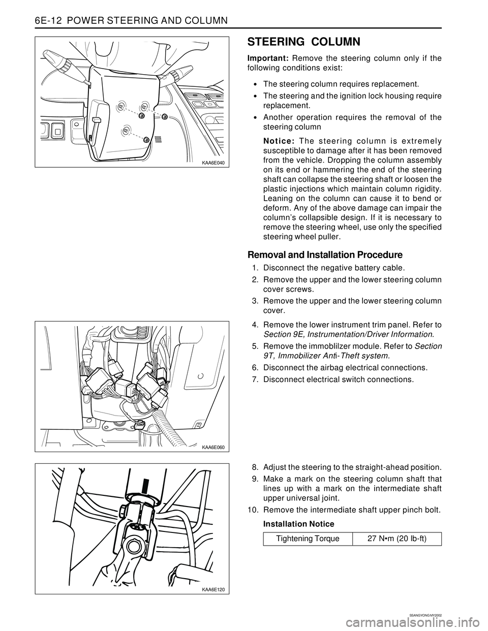
1. Disconnect the negative battery cable.
2. Remove the upper and the lower steering column
cover screws.
3. Remove the upper and the lower steering column
cover.
KAA6E060
4. Remove the lower instrument trim panel. Refer to
Section 9E, Instrumentation/Driver Information.
5. Remove the immoblilzer module. Refer to Section
9T, Immobilizer Anti-Theft system.
6. Disconnect the airbag electrical connections.
7. Disconnect electrical switch connections.
8. Adjust the steering to the straight-ahead position.
9. Make a mark on the steering column shaft that
lines up with a mark on the intermediate shaft
upper universal joint.
10. Remove the intermediate shaft upper pinch bolt.
Installation Notice
Tightening Torque 27 Nm (20 lb-ft)
Page 1664 of 2053

BODY WIRING SYSTEM 9A-13
SSANGYONG MY2002
1 C351
2 S201
3 G201
4 G202
5 Auto down unit
6 HLLD switch
7 OSRV switch
8 Rear wiper & washer switch
9 C201
10 Clutch switch “A”
11 Clutch switch “B” (Gasoline E/G)
12 Stop lamp switch
13 Dimmer & passing switch
14 Turn signal,FRT fog lamp & Light switch
15 Wiper switch
16 J201
17 C202
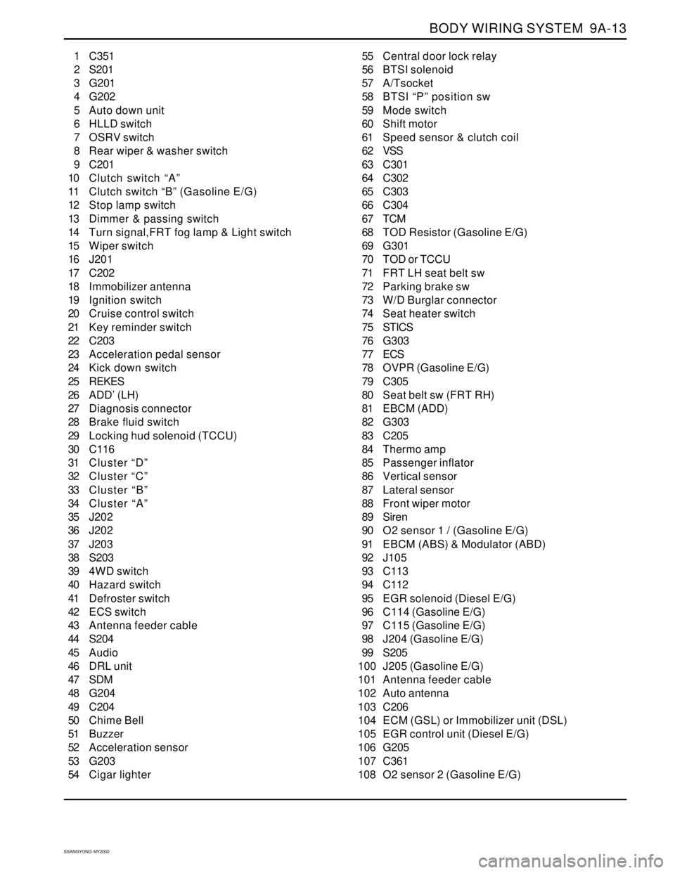
18 Immobilizer antenna
19 Ignition switch
20 Cruise control switch
21 Key reminder switch
22 C203
23 Acceleration pedal sensor
24 Kick down switch
25 REKES
26 ADD’ (LH)
27 Diagnosis connector
28 Brake fluid switch
29 Locking hud solenoid (TCCU)
30 C116
31 Cluster “D”
32 Cluster “C”
33 Cluster “B”
34 Cluster “A”
35 J202
36 J202
37 J203
38 S203
39 4WD switch
40 Hazard switch
41 Defroster switch
42 ECS switch
43 Antenna feeder cable
44 S204
45 Audio
46 DRL unit
47 SDM
48 G204
49 C204
50 Chime Bell
51 Buzzer
52 Acceleration sensor
53 G203
54 Cigar lighter55 Central door lock relay
56 BTSI solenoid
57 A/Tsocket
58 BTSI “P” position sw
59 Mode switch
60 Shift motor
61 Speed sensor & clutch coil
62 VSS
63 C301
64 C302
65 C303
66 C304
67 TCM
68 TOD Resistor (Gasoline E/G)
69 G301
70 TOD or TCCU
71 FRT LH seat belt sw
72 Parking brake sw
73 W/D Burglar connector
74 Seat heater switch
75 STICS
76 G303
77 ECS
78 OVPR (Gasoline E/G)
79 C305
80 Seat belt sw (FRT RH)
81 EBCM (ADD)
82 G303
83 C205
84 Thermo amp
85 Passenger inflator
86 Vertical sensor
87 Lateral sensor
88 Front wiper motor
89 Siren
90 O2 sensor 1 / (Gasoline E/G)
91 EBCM (ABS) & Modulator (ABD)
92 J105
93 C113
94 C112
95 EGR solenoid (Diesel E/G)
96 C114 (Gasoline E/G)
97 C115 (Gasoline E/G)
98 J204 (Gasoline E/G)
99 S205
100 J205 (Gasoline E/G)
101 Antenna feeder cable
102 Auto antenna
103 C206
104 ECM (GSL) or Immobilizer unit (DSL)
105 EGR control unit (Diesel E/G)
106 G205
107 C361
108 O2 sensor 2 (Gasoline E/G)
Page 1857 of 2053

SECTION 9T2
IMMOBILIZER SYSTEM
CAUTION: Disconnect the negative battery cable before removing or installing any electrical unit or when a
tool or equipment could easily come in contact with exposed electrical terminals. Disconnecting this cable
will help prevent personal injury and damage to the vehicle. The ignition must also be in LOCK unless
otherwise noted.
TABLE OF CONTENTS
Description and Operation.................................9T2-2
Components Locator..........................................9T2-3
Immobilizer System...........................................9T2-3
Repair Instructions..............................................9T2-4
On-Vehicle Service Unit Repair..............................9T2-4Immobilizer Antenna ..........................................9T2-4
Transponder Replacement.................................9T2-4
Schematic and Routing Diagrams.....................9T2-5
Immobilizer System (Diesel : Vod).....................9T2-5