1997 SSANGYONG KORANDO bulb
[x] Cancel search: bulbPage 1002 of 2053
ABS AND TCS 4F-19
SSANGYONG MY2002
Step
1
2
3
4
5
6
7
8
9
10
11
12
13
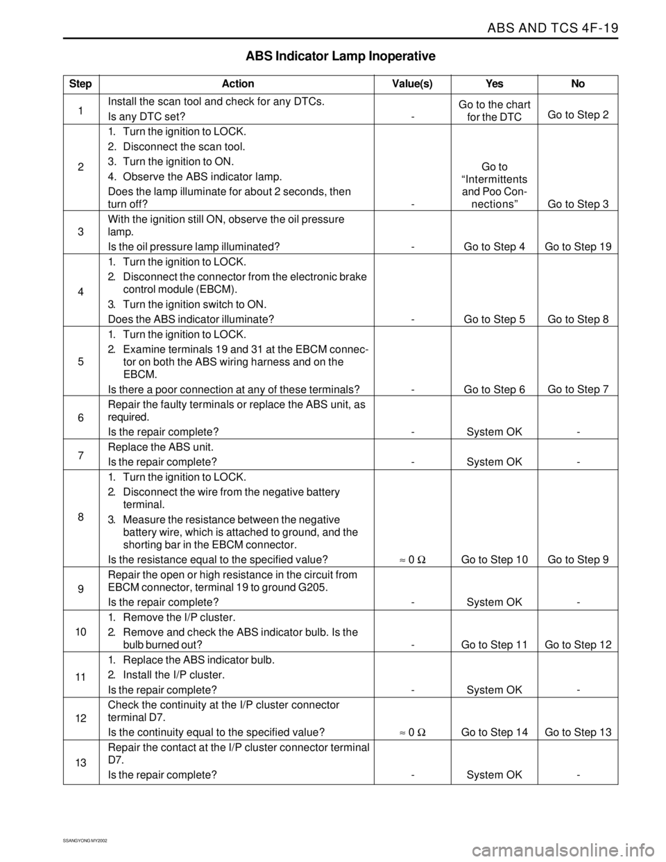
ABS Indicator Lamp Inoperative
Action Yes
Go to the chart
for the DTC
Go to
“Intermittents
and Poo Con-
nections”
Go to Step 4
Go to Step 5
Go to Step 6
System OK
System OK
Go to Step 10
System OK
Go to Step 11
System OK
Go to Step 14
System OKNo
Go to Step 2
Go to Step 3
Go to Step 19
Go to Step 8
Go to Step 7
-
-
Go to Step 9
-
Go to Step 12
-
Go to Step 13
- Value(s)
Install the scan tool and check for any DTCs.
Is any DTC set?
1. Turn the ignition to LOCK.
2. Disconnect the scan tool.
3. Turn the ignition to ON.
4. Observe the ABS indicator lamp.
Does the lamp illuminate for about 2 seconds, then
turn off?
With the ignition still ON, observe the oil pressure
lamp.
Is the oil pressure lamp illuminated?
1. Turn the ignition to LOCK.
2. Disconnect the connector from the electronic brake
control module (EBCM).
3. Turn the ignition switch to ON.
Does the ABS indicator illuminate?
1. Turn the ignition to LOCK.
2. Examine terminals 19 and 31 at the EBCM connec-
tor on both the ABS wiring harness and on the
EBCM.
Is there a poor connection at any of these terminals?
Repair the faulty terminals or replace the ABS unit, as
required.
Is the repair complete?
Replace the ABS unit.
Is the repair complete?
1. Turn the ignition to LOCK.
2. Disconnect the wire from the negative battery
terminal.
3. Measure the resistance between the negative
battery wire, which is attached to ground, and the
shorting bar in the EBCM connector.
Is the resistance equal to the specified value?
Repair the open or high resistance in the circuit from
EBCM connector, terminal 19 to ground G205.
Is the repair complete?
1. Remove the I/P cluster.
2. Remove and check the ABS indicator bulb. Is the
bulb burned out?
1. Replace the ABS indicator bulb.
2. Install the I/P cluster.
Is the repair complete?
Check the continuity at the I/P cluster connector
terminal D7.
Is the continuity equal to the specified value?
Repair the contact at the I/P cluster connector terminal
D7.
Is the repair complete?
-
-
-
-
-
-
-
≈ 0 Ω
-
-
-
≈ 0 Ω
-
Page 1006 of 2053
ABS AND TCS 4F-23
SSANGYONG MY2002
Step
1
2
3
4
5
6
7
8
9
10
11
12
13
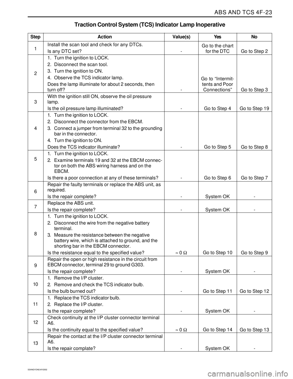
Traction Control System (TCS) Indicator Lamp Inoperative
Action Yes NoValue(s)
Install the scan tool and check for any DTCs.
Is any DTC set?
1. Turn the ignition to LOCK.
2. Disconnect the scan tool.
3. Turn the ignition to ON.
4. Observe the TCS indicator lamp.
Does the lamp illuminate for about 2 seconds, then
turn off?
With the ignition still ON, observe the oil pressure
lamp.
Is the oil pressure lamp illuminated?
1. Turn the ignition to LOCK.
2. Disconnect the connector from the EBCM.
3. Connect a jumper from terminal 32 to the grounding
bar in the connector.
4. Turn the ignition to ON.
Does the TCS indicator illuminate?
1. Turn the ignition to LOCK.
2. Examine terminals 19 and 32 at the EBCM connec-
tor on both the ABS wiring harness and on the
EBCM.
Is there a poor connection at any of these terminals?
Repair the faulty terminals or replace the ABS unit, as
required.
Is the repair complete?
Replace the ABS unit.
Is the repair complete?
1. Turn the ignition to LOCK.
2. Disconnect the wire from the negative battery
terminal.
3. Measure the resistance between the negative
battery wire, which is attached to ground, and the
shorting bar in the EBCM connector.
Is the resistance equal to the specified value?
Repair the open or high resistance in the circuit from
EBCM connector, terminal 29 to ground G303.
Is the repair complete?
1. Remove the I/P cluster.
2. Remove and check the TCS indicator bulb.
Is the bulb burned out?
1. Replace the TCS indicator bulb.
2. Replace the I/P cluster.
Is the repair complete?
Check continuity at the I/P cluster connector terminal
A6.
Is the continuity equal to the specified value?
Repair the contact at the I/P cluster connector terminal
A6.
Is the repair complate?
-
-
-
-
-
-
-
≈ 0 Ω
-
-
-
≈ 0 Ω
-Go to the chart
for the DTC
Go to “Intermit-
tents and Poor
Connections”
Go to Step 4
Go to Step 5
Go to Step 6
System OK
System OK
Go to Step 10
System OK
Go to Step 11
System OK
Go to Step 14
System OKGo to Step 2
Go to Step 3
Go to Step 19
Go to Step 8
Go to Step 7
-
-
Go to Step 9
-
Go to Step 12
-
Go to Step 13
-
Page 1010 of 2053
ABS AND TCS 4F-27
SSANGYONG MY2002
Step
1
2
3
4
5
6
7
8
9
10
11
12
13
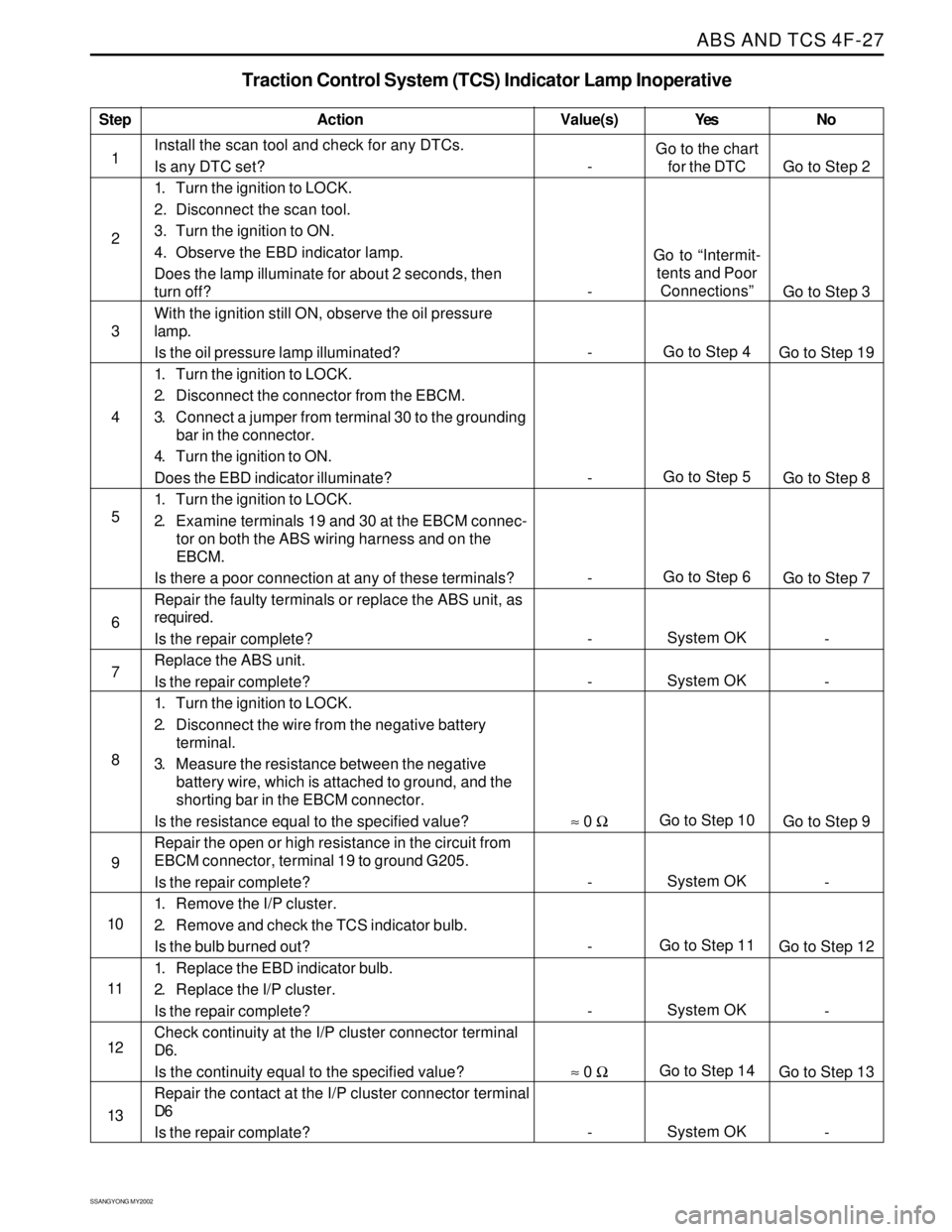
Traction Control System (TCS) Indicator Lamp Inoperative
Action
Go to the chart
for the DTC
Go to “Intermit-
tents and Poor
Connections”
Go to Step 4
Go to Step 5
Go to Step 6
System OK
System OK
Go to Step 10
System OK
Go to Step 11
System OK
Go to Step 14
System OKGo to Step 2
Go to Step 3
Go to Step 19
Go to Step 8
Go to Step 7
-
-
Go to Step 9
-
Go to Step 12
-
Go to Step 13
- Value(s)
Install the scan tool and check for any DTCs.
Is any DTC set?
1. Turn the ignition to LOCK.
2. Disconnect the scan tool.
3. Turn the ignition to ON.
4. Observe the EBD indicator lamp.
Does the lamp illuminate for about 2 seconds, then
turn off?
With the ignition still ON, observe the oil pressure
lamp.
Is the oil pressure lamp illuminated?
1. Turn the ignition to LOCK.
2. Disconnect the connector from the EBCM.
3. Connect a jumper from terminal 30 to the grounding
bar in the connector.
4. Turn the ignition to ON.
Does the EBD indicator illuminate?
1. Turn the ignition to LOCK.
2. Examine terminals 19 and 30 at the EBCM connec-
tor on both the ABS wiring harness and on the
EBCM.
Is there a poor connection at any of these terminals?
Repair the faulty terminals or replace the ABS unit, as
required.
Is the repair complete?
Replace the ABS unit.
Is the repair complete?
1. Turn the ignition to LOCK.
2. Disconnect the wire from the negative battery
terminal.
3. Measure the resistance between the negative
battery wire, which is attached to ground, and the
shorting bar in the EBCM connector.
Is the resistance equal to the specified value?
Repair the open or high resistance in the circuit from
EBCM connector, terminal 19 to ground G205.
Is the repair complete?
1. Remove the I/P cluster.
2. Remove and check the TCS indicator bulb.
Is the bulb burned out?
1. Replace the EBD indicator bulb.
2. Replace the I/P cluster.
Is the repair complete?
Check continuity at the I/P cluster connector terminal
D6.
Is the continuity equal to the specified value?
Repair the contact at the I/P cluster connector terminal
D6
Is the repair complate?
-
-
-
-
-
-
-
≈ 0 Ω
-
-
-
≈ 0 Ω
-Yes No
Page 1198 of 2053
AUTOMATIC TRANSMISSION 5A-103
SSANGYONG MY2002
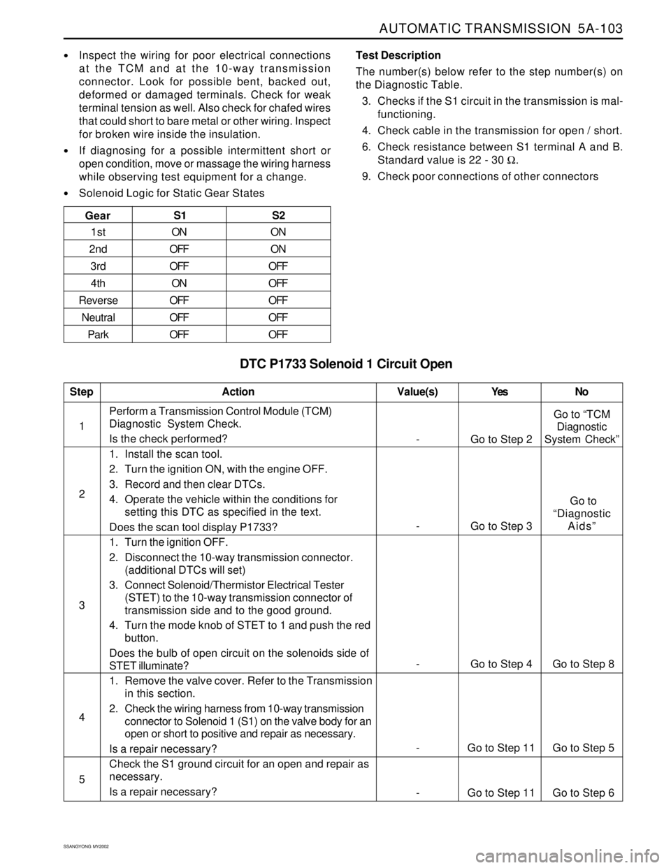
DTC P1733 Solenoid 1 Circuit Open
Inspect the wiring for poor electrical connections
at the TCM and at the 10-way transmission
connector. Look for possible bent, backed out,
deformed or damaged terminals. Check for weak
terminal tension as well. Also check for chafed wires
that could short to bare metal or other wiring. Inspect
for broken wire inside the insulation.
If diagnosing for a possible intermittent short or
open condition, move or massage the wiring harness
while observing test equipment for a change.
Solenoid Logic for Static Gear StatesTest Description
The number(s) below refer to the step number(s) on
the Diagnostic Table.
3. Checks if the S1 circuit in the transmission is mal-
functioning.
4. Check cable in the transmission for open / short.
6. Check resistance between S1 terminal A and B.
Standard value is 22 - 30 Ω.
9. Check poor connections of other connectors
1Perform a Transmission Control Module (TCM)
Diagnostic System Check.
Is the check performed?
1. Install the scan tool.
2. Turn the ignition ON, with the engine OFF.
3. Record and then clear DTCs.
4. Operate the vehicle within the conditions for
setting this DTC as specified in the text.
Does the scan tool display P1733?
1. Turn the ignition OFF.
2. Disconnect the 10-way transmission connector.
(additional DTCs will set)
3. Connect Solenoid/Thermistor Electrical Tester
(STET) to the 10-way transmission connector of
transmission side and to the good ground.
4. Turn the mode knob of STET to 1 and push the red
button.
Does the bulb of open circuit on the solenoids side of
STET illuminate?
1. Remove the valve cover. Refer to the Transmission
in this section.
2. Check the wiring harness from 10-way transmission
connector to Solenoid 1 (S1) on the valve body for an
open or short to positive and repair as necessary.
Is a repair necessary?
Check the S1 ground circuit for an open and repair as
necessary.
Is a repair necessary?
StepAction Value(s) Yes No
2
3
- Go to Step 4 Go to Step 8
4
5
- Go to Step 2Go to “TCM
Diagnostic
System Check”
- Go to Step 3 Go to
“Diagnostic
Aids”
- Go to Step 11 Go to Step 6
- Go to Step 11 Go to Step 5 Gear
S1 S2
1st
2nd
3rd
4th
Reverse
Neutral
ParkON
OFF
OFF
ON
OFF
OFF
OFFON
ON
OFF
OFF
OFF
OFF
OFF
Page 1202 of 2053
AUTOMATIC TRANSMISSION 5A-107
SSANGYONG MY2002
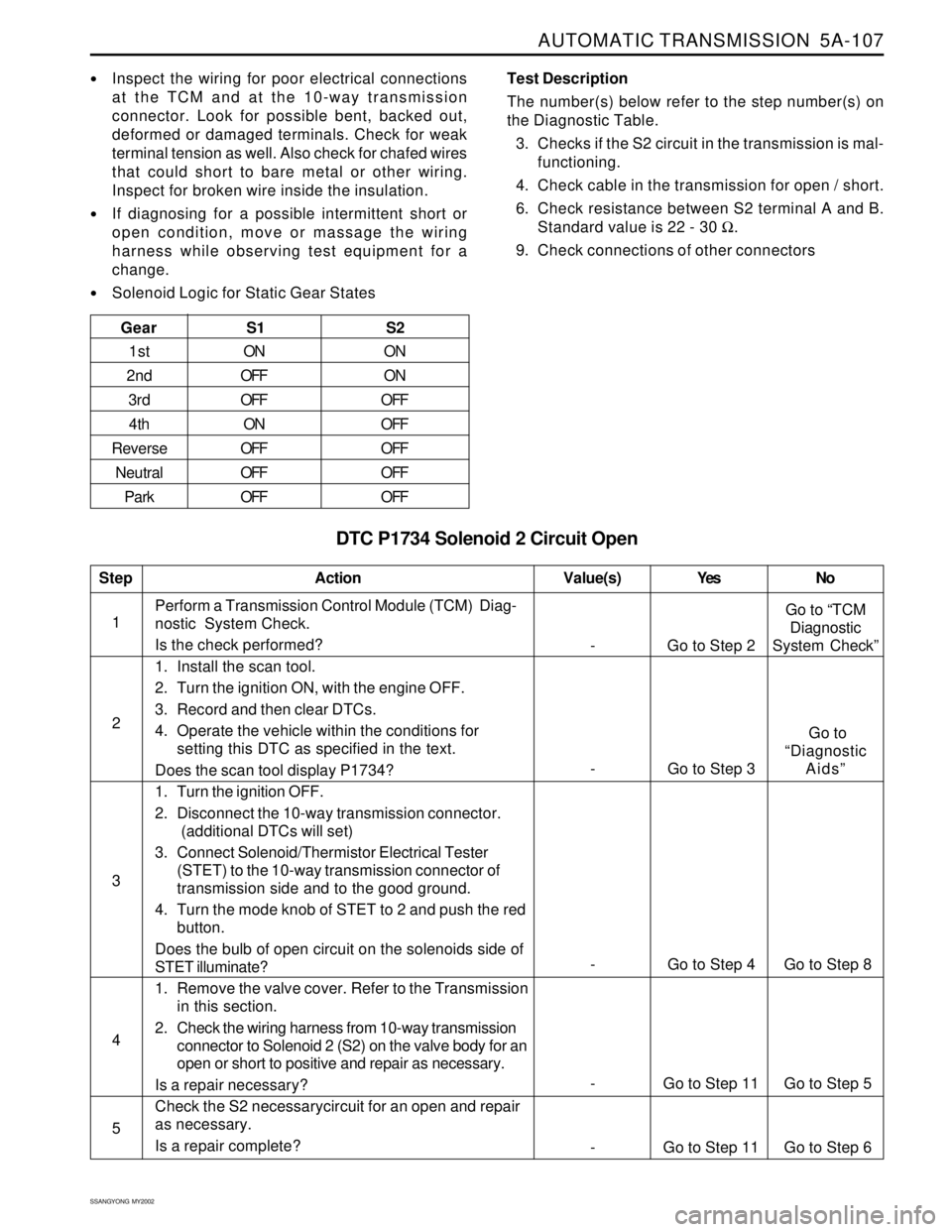
DTC P1734 Solenoid 2 Circuit Open
Inspect the wiring for poor electrical connections
at the TCM and at the 10-way transmission
connector. Look for possible bent, backed out,
deformed or damaged terminals. Check for weak
terminal tension as well. Also check for chafed wires
that could short to bare metal or other wiring.
Inspect for broken wire inside the insulation.
If diagnosing for a possible intermittent short or
open condition, move or massage the wiring
harness while observing test equipment for a
change.
Solenoid Logic for Static Gear StatesTest Description
The number(s) below refer to the step number(s) on
the Diagnostic Table.
3. Checks if the S2 circuit in the transmission is mal-
functioning.
4. Check cable in the transmission for open / short.
6. Check resistance between S2 terminal A and B.
Standard value is 22 - 30 Ω.
9. Check connections of other connectors
Gear
S1 S2
1st
2nd
3rd
4th
Reverse
Neutral
ParkON
OFF
OFF
ON
OFF
OFF
OFFON
ON
OFF
OFF
OFF
OFF
OFF
1Perform a Transmission Control Module (TCM) Diag-
nostic System Check.
Is the check performed?
1. Install the scan tool.
2. Turn the ignition ON, with the engine OFF.
3. Record and then clear DTCs.
4. Operate the vehicle within the conditions for
setting this DTC as specified in the text.
Does the scan tool display P1734?
1. Turn the ignition OFF.
2. Disconnect the 10-way transmission connector.
(additional DTCs will set)
3. Connect Solenoid/Thermistor Electrical Tester
(STET) to the 10-way transmission connector of
transmission side and to the good ground.
4. Turn the mode knob of STET to 2 and push the red
button.
Does the bulb of open circuit on the solenoids side of
STET illuminate?
1. Remove the valve cover. Refer to the Transmission
in this section.
2. Check the wiring harness from 10-way transmission
connector to Solenoid 2 (S2) on the valve body for an
open or short to positive and repair as necessary.
Is a repair necessary?
Check the S2 necessarycircuit for an open and repair
as necessary.
Is a repair complete?
StepAction Value(s) Yes No
2
3
- Go to Step 4 Go to Step 8
4
5
- Go to Step 2Go to “TCM
Diagnostic
System Check”
- Go to Step 3 Go to
“Diagnostic
Aids”
- Go to Step 11 Go to Step 6
- Go to Step 11 Go to Step 5
Page 1206 of 2053
AUTOMATIC TRANSMISSION 5A-111
SSANGYONG MY2002
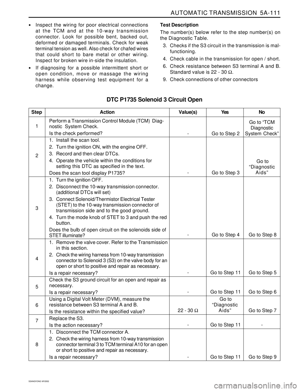
DTC P1735 Solenoid 3 Circuit Open
Inspect the wiring for poor electrical connections
at the TCM and at the 10-way transmission
connector. Look for possible bent, backed out,
deformed or damaged terminals. Check for weak
terminal tension as well. Also check for chafed wires
that could short to bare metal or other wiring.
Inspect for broken wire in-side the insulation.
If diagnosing for a possible intermittent short or
open condition, move or massage the wiring
harness while observing test equipment for a
change.Test Description
The number(s) below refer to the step number(s) on
the Diagnostic Table.
3. Checks if the S3 circuit in the transmission is mal-
functioning.
4. Check cable in the transmission for open / short.
6. Check resistance between S3 terminal A and B.
Standard value is 22 - 30 Ω.
9. Check connections of other connectors
1Perform a Transmission Control Module (TCM) Diag-
nostic System Check.
Is the check performed?
1. Install the scan tool.
2. Turn the ignition ON, with the engine OFF.
3. Record and then clear DTCs.
4. Operate the vehicle within the conditions for
setting this DTC as specified in the text.
Does the scan tool display P1735?
1. Turn the ignition OFF.
2. Disconnect the 10-way transmission connector.
(additional DTCs will set)
3. Connect Solenoid/Thermistor Electrical Tester
(STET) to the 10-way transmission connector of
transmission side and to the good ground.
4. Turn the mode knob of STET to 3 and push the red
button.
Does the bulb of open circuit on the solenoids side of
STET illuminate?
1. Remove the valve cover. Refer to the Transmission
in this section.
2. Check the wiring harness from 10-way transmission
connector to Solenoid 3 (S3) on the valve body for an
open or short to positive and repair as necessary.
Is a repair necessary?
Check the S3 ground circuit for an open and repair as
necessary.
Is a repair necessary?
Using a Digital Volt Meter (DVM), measure the
resistance between S3 terminal A and B.
Is the resistance within the specified value?
Replace the S3.
Is the action necessary?
1. Disconnect the TCM connector A.
2. Check the wiring harness from 10-way transmission
connector terminal 3 to TCM terminal A10 for an open
or short to positive and repair as necessary.
Is a repair necessary?
StepAction Value(s) Yes No
2
3
- Go to Step 4 Go to Step 8
4
5
- Go to Step 2Go to “TCM
Diagnostic
System Check”
- Go to Step 3 Go to
“Diagnostic
Aids”
- Go to Step 11 Go to Step 9
- Go to Step 11 Go to Step 5
22 - 30 Ω Go to Step 7 Go to
“Diagnostic
Aids”
- Go to Step 11 -
- Go to Step 11 Go to Step 6
6
7
8
Page 1210 of 2053
AUTOMATIC TRANSMISSION 5A-115
SSANGYONG MY2002
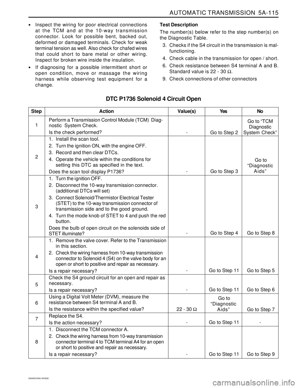
DTC P1736 Solenoid 4 Circuit Open
Inspect the wiring for poor electrical connections
at the TCM and at the 10-way transmission
connector. Look for possible bent, backed out,
deformed or damaged terminals. Check for weak
terminal tension as well. Also check for chafed wires
that could short to bare metal or other wiring.
Inspect for broken wire inside the insulation.
If diagnosing for a possible intermittent short or
open condition, move or massage the wiring
harness while observing test equipment for a
change.Test Description
The number(s) below refer to the step number(s) on
the Diagnostic Table.
3. Checks if the S4 circuit in the transmission is mal-
functioning.
4. Check cable in the transmission for open / short.
6. Check resistance between S4 terminal A and B.
Standard value is 22 - 30 Ω.
9. Check connections of other connectors
1Perform a Transmission Control Module (TCM) Diag-
nostic System Check.
Is the check performed?
1. Install the scan tool.
2. Turn the ignition ON, with the engine OFF.
3. Record and then clear DTCs.
4. Operate the vehicle within the conditions for
setting this DTC as specified in the text.
Does the scan tool display P1736?
1. Turn the ignition OFF.
2. Disconnect the 10-way transmission connector.
(additional DTCs will set)
3. Connect Solenoid/Thermistor Electrical Tester
(STET) to the 10-way transmission connector of
transmission side and to the good ground.
4. Turn the mode knob of STET to 4 and push the red
button.
Does the bulb of open circuit on the solenoids side of
STET illuminate?
1. Remove the valve cover. Refer to the Transmission
in this section.
2. Check the wiring harness from 10-way transmission
connector to Solenoid 4 (S4) on the valve body for an
open or short to positive and repair as necessary.
Is a repair necessary?
Check the S4 ground circuit for an open and repair as
necessary.
Is a repair necessary?
Using a Digital Volt Meter (DVM), measure the
resistance between S4 terminal A and B.
Is the resistance within the specified value?
Replace the S4.
Is the action necessary?
1. Disconnect the TCM connector A.
2. Check the wiring harness from 10-way transmission
connector terminal 4 to TCM terminal A4 for an open
or short to positive and repair as necessary.
Is a repair necessary?
StepAction Value(s) Yes No
2
3
- Go to Step 4 Go to Step 8
4
5
- Go to Step 2Go to “TCM
Diagnostic
System Check”
- Go to Step 3 Go to
“Diagnostic
Aids”
- Go to Step 11 Go to Step 9
- Go to Step 11 Go to Step 5
22 - 30 Ω
Go to Step 7 Go to
“Diagnostic
Aids”
- Go to Step 11 -
- Go to Step 11 Go to Step 6
6
7
8
Page 1214 of 2053
AUTOMATIC TRANSMISSION 5A-119
SSANGYONG MY2002
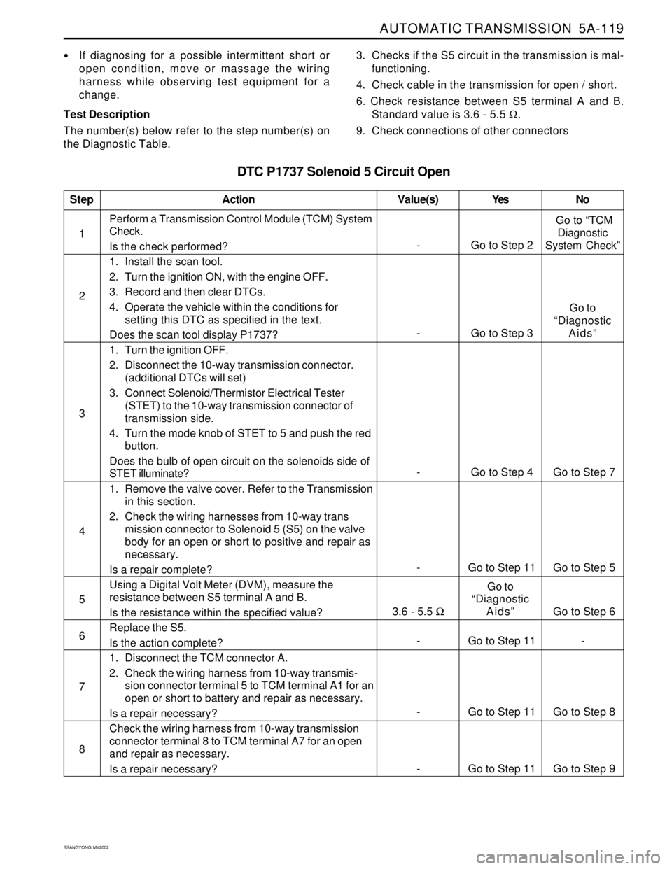
DTC P1737 Solenoid 5 Circuit Open
If diagnosing for a possible intermittent short or
open condition, move or massage the wiring
harness while observing test equipment for a
change.
Test Description
The number(s) below refer to the step number(s) on
the Diagnostic Table.3. Checks if the S5 circuit in the transmission is mal-
functioning.
4. Check cable in the transmission for open / short.
6. Check resistance between S5 terminal A and B.
Standard value is 3.6 - 5.5 Ω.
9. Check connections of other connectors
1Perform a Transmission Control Module (TCM) System
Check.
Is the check performed?
1. Install the scan tool.
2. Turn the ignition ON, with the engine OFF.
3. Record and then clear DTCs.
4. Operate the vehicle within the conditions for
setting this DTC as specified in the text.
Does the scan tool display P1737?
1. Turn the ignition OFF.
2. Disconnect the 10-way transmission connector.
(additional DTCs will set)
3. Connect Solenoid/Thermistor Electrical Tester
(STET) to the 10-way transmission connector of
transmission side.
4. Turn the mode knob of STET to 5 and push the red
button.
Does the bulb of open circuit on the solenoids side of
STET illuminate?
1. Remove the valve cover. Refer to the Transmission
in this section.
2. Check the wiring harnesses from 10-way trans
mission connector to Solenoid 5 (S5) on the valve
body for an open or short to positive and repair as
necessary.
Is a repair complete?
Using a Digital Volt Meter (DVM), measure the
resistance between S5 terminal A and B.
Is the resistance within the specified value?
Replace the S5.
Is the action complete?
1. Disconnect the TCM connector A.
2. Check the wiring harness from 10-way transmis-
sion connector terminal 5 to TCM terminal A1 for an
open or short to battery and repair as necessary.
Is a repair necessary?
Check the wiring harness from 10-way transmission
connector terminal 8 to TCM terminal A7 for an open
and repair as necessary.
Is a repair necessary?
StepAction Value(s) Yes No
2
3
- Go to Step 2 Go to “TCM
Diagnostic
System Check”
- Go to Step 4 Go to Step 7
5 4
- Go to Step 11 Go to Step 5
- Go to Step 3Go to
“Diagnostic
Aids”
- Go to Step 11 Go to Step 8 6
- Go to Step 11 -
7
8
- Go to Step 11 Go to Step 9
3.6 - 5.5 ΩGo to
“Diagnostic
Aids” Go to Step 6