Page 1685 of 2053

LIGHTING SYSTEM 9B-11
SSANGYONG MY2002
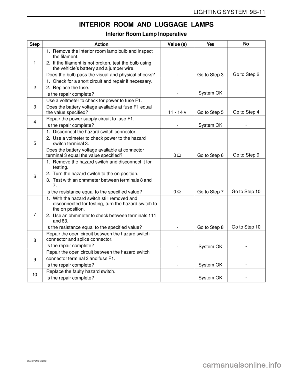
INTERIOR ROOM AND LUGGAGE LAMPS
Interior Room Lamp Inoperative
Step
1
2
3
4
5
6
7
8
9
10Action
1. Remove the interior room lamp bulb and inspect
the filament.
2. If the filament is not broken, test the bulb using
the vehicle’s battery and a jumper wire.
Does the bulb pass the visual and physical checks?
1. Check for a short circuit and repair if necessary.
2. Replace the fuse.
Is the repair complete?
Use a voltmeter to check for power to fuse F1.
Does the battery voltage available at fuse F1 equal
the value specified?
Repair the power supply circuit to fuse F1.
Is the repair complete?
1. Disconnect the hazard switch connector.
2. Use a volmeter to check power to the hazard
switch terminal 3.
Does the battery voltage available at connector
terminal 3 equal the value specified?
1. Remove the hazard switch and disconnect it for
testing.
2. Turn the hazard switch to the on position.
3. Test with an ohmmeter between terminals 8 and
7.
Is the resistance equal to the specified value?
1. With the hazard switch still removed and
disconnected for testing, turn the hazard switch to
the on position.
2. Use an ohmmeter to check between terminals 111
and 63.
Is the resistance equal to the specified value?
Repair the open circuit between the hazard switch
connector and splice connector.
Is the repair complete?
Repair the open circuit between the hazard switch
connector terminal 3 and fuse F1.
Is the repair complete?
Replace the faulty hazard switch.
Is the repair complete?Yes
Go to Step 3
System OK
Go to Step 5
System OK
Go to Step 6
Go to Step 7
Go to Step 8
System OK
System OK
System OKNo
Go to Step 2
-
Go to Step 4
-
Go to Step 9
Go to Step 10
Go to Step 10
-
-
- Value (s)
-
-
11 - 14 v
-
0 Ω
0 Ω
-
-
-
-
Page 1686 of 2053

SSANGYONG MY2002
9B-12 LIGHTING SYSTEM
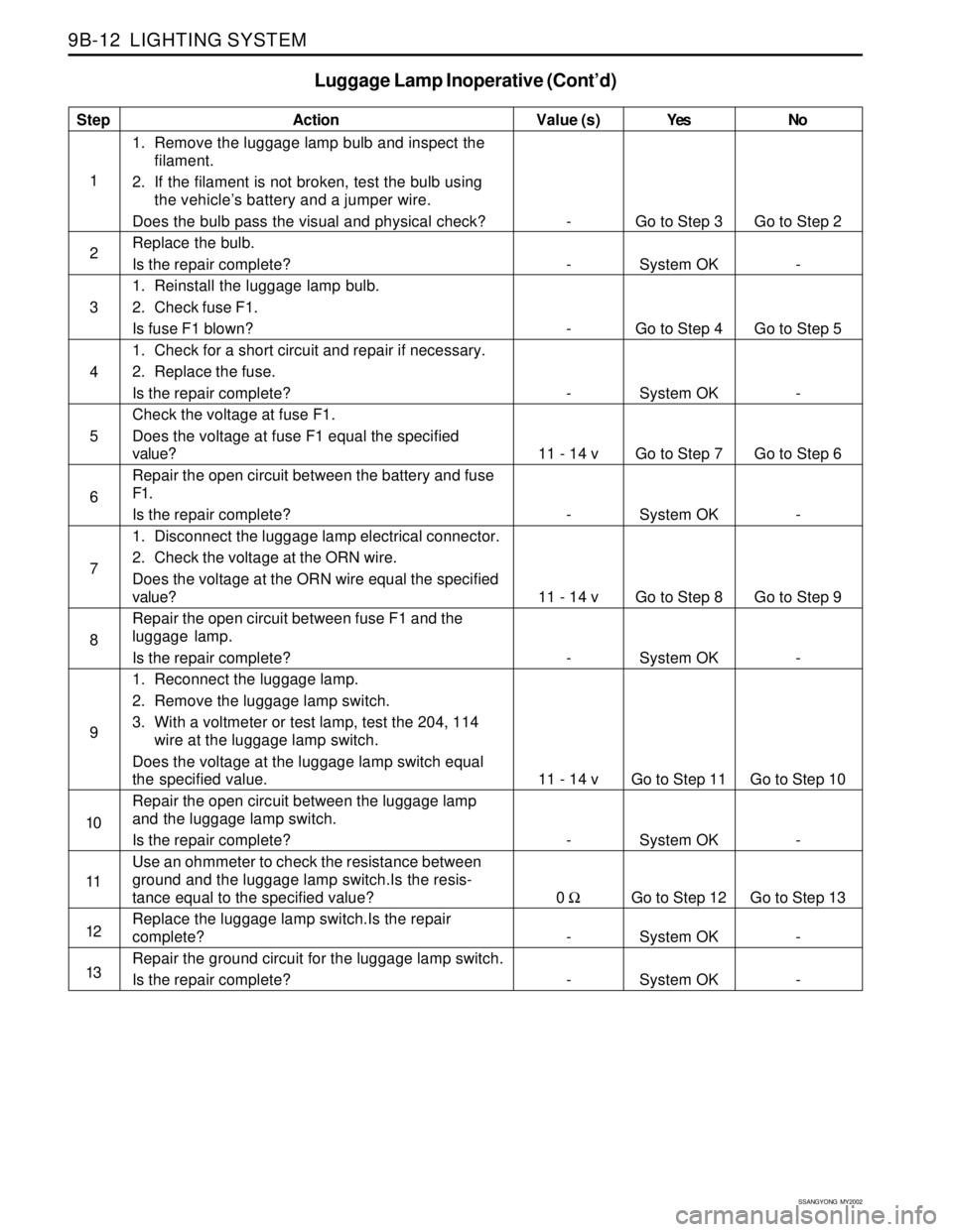
Luggage Lamp Inoperative (Cont’d)
Step
1
2
3
4
5
6
7
8
9
10
11
12
13Action
1. Remove the luggage lamp bulb and inspect the
filament.
2. If the filament is not broken, test the bulb using
the vehicle’s battery and a jumper wire.
Does the bulb pass the visual and physical check?
Replace the bulb.
Is the repair complete?
1. Reinstall the luggage lamp bulb.
2. Check fuse F1.
Is fuse F1 blown?
1. Check for a short circuit and repair if necessary.
2. Replace the fuse.
Is the repair complete?
Check the voltage at fuse F1.
Does the voltage at fuse F1 equal the specified
value?
Repair the open circuit between the battery and fuse
F1.
Is the repair complete?
1. Disconnect the luggage lamp electrical connector.
2. Check the voltage at the ORN wire.
Does the voltage at the ORN wire equal the specified
value?
Repair the open circuit between fuse F1 and the
luggage lamp.
Is the repair complete?
1. Reconnect the luggage lamp.
2. Remove the luggage lamp switch.
3. With a voltmeter or test lamp, test the 204, 114
wire at the luggage lamp switch.
Does the voltage at the luggage lamp switch equal
the specified value.
Repair the open circuit between the luggage lamp
and the luggage lamp switch.
Is the repair complete?
Use an ohmmeter to check the resistance between
ground and the luggage lamp switch.Is the resis-
tance equal to the specified value?
Replace the luggage lamp switch.Is the repair
complete?
Repair the ground circuit for the luggage lamp switch.
Is the repair complete?Yes
Go to Step 3
System OK
Go to Step 4
System OK
Go to Step 7
System OK
Go to Step 8
System OK
Go to Step 11
System OK
Go to Step 12
System OK
System OKNo
Go to Step 2
-
Go to Step 5
-
Go to Step 6
-
Go to Step 9
-
Go to Step 10
-
Go to Step 13
-
- Value (s)
-
-
-
-
11 - 14 v
-
11 - 14 v
-
11 - 14 v
-
0 Ω
-
-
Page 1687 of 2053

LIGHTING SYSTEM 9B-13
SSANGYONG MY2002
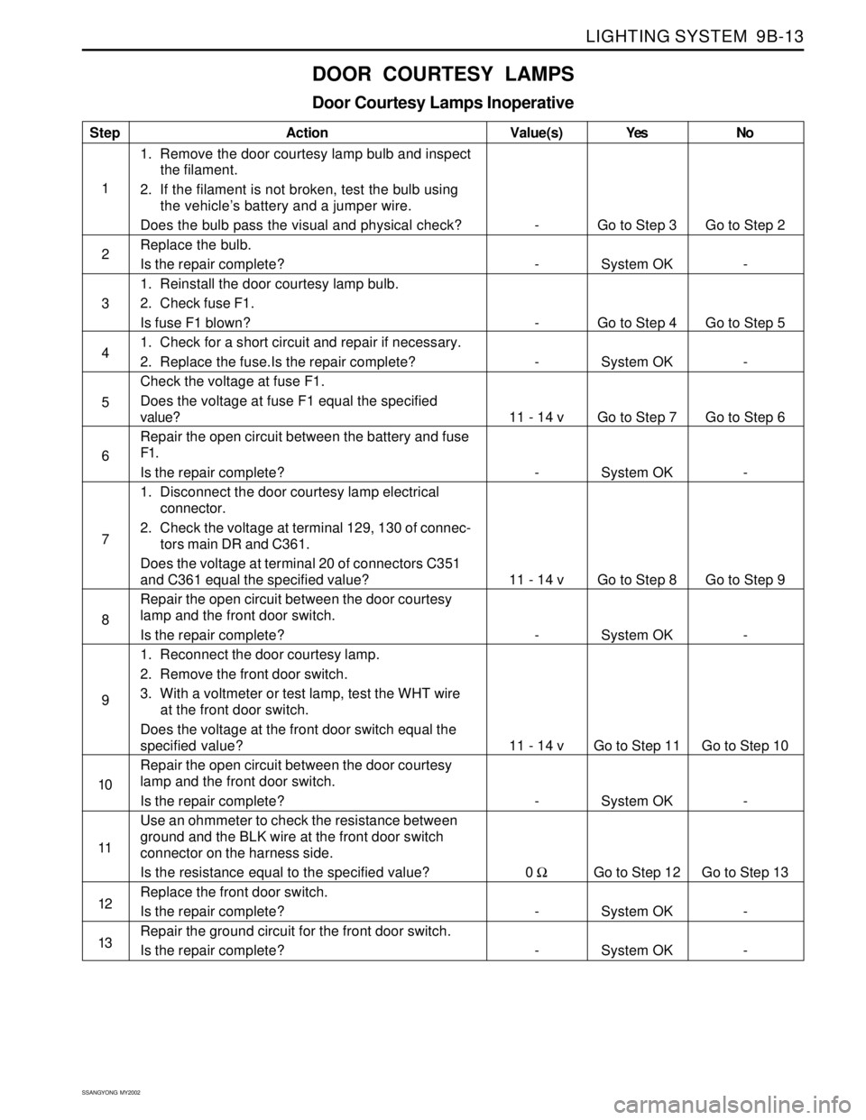
DOOR COURTESY LAMPS
Door Courtesy Lamps Inoperative
Step
1
2
3
4
5
6
7
8
9
10
11
12
13Action
1. Remove the door courtesy lamp bulb and inspect
the filament.
2. If the filament is not broken, test the bulb using
the vehicle’s battery and a jumper wire.
Does the bulb pass the visual and physical check?
Replace the bulb.
Is the repair complete?
1. Reinstall the door courtesy lamp bulb.
2. Check fuse F1.
Is fuse F1 blown?
1. Check for a short circuit and repair if necessary.
2. Replace the fuse.Is the repair complete?
Check the voltage at fuse F1.
Does the voltage at fuse F1 equal the specified
value?
Repair the open circuit between the battery and fuse
F1.
Is the repair complete?
1. Disconnect the door courtesy lamp electrical
connector.
2. Check the voltage at terminal 129, 130 of connec-
tors main DR and C361.
Does the voltage at terminal 20 of connectors C351
and C361 equal the specified value?
Repair the open circuit between the door courtesy
lamp and the front door switch.
Is the repair complete?
1. Reconnect the door courtesy lamp.
2. Remove the front door switch.
3. With a voltmeter or test lamp, test the WHT wire
at the front door switch.
Does the voltage at the front door switch equal the
specified value?
Repair the open circuit between the door courtesy
lamp and the front door switch.
Is the repair complete?
Use an ohmmeter to check the resistance between
ground and the BLK wire at the front door switch
connector on the harness side.
Is the resistance equal to the specified value?
Replace the front door switch.
Is the repair complete?
Repair the ground circuit for the front door switch.
Is the repair complete?Yes
Go to Step 3
System OK
Go to Step 4
System OK
Go to Step 7
System OK
Go to Step 8
System OK
Go to Step 11
System OK
Go to Step 12
System OK
System OKNo
Go to Step 2
-
Go to Step 5
-
Go to Step 6
-
Go to Step 9
-
Go to Step 10
-
Go to Step 13
-
- Value(s)
-
-
-
-
11 - 14 v
-
11 - 14 v
-
11 - 14 v
-
0 Ω
-
-
Page 1689 of 2053
LIGHTING SYSTEM 9B-15
SSANGYONG MY2002
REPAIR INSTRUCTIONS
KAA9B020
KAA9B030
ON-VEHICLE SERVICE
UNIT REPAIR
HEAD LAMPS
Removal and Installation Procedure
1. Open the hood.
2. Disconnect the negative battery cable.
3. Remove screws and row the radiator grille.
Installation Notice
Dissimilar metals in direct contact with each
other may corrode rapidly. Make sure to use
the correct fasteners to prevent premature
corrosion.
4. Disconnect the headlamp assembly electrical con-
nector.
5. Remove the headlamp.
Installation Notice
Dissimilar metals in direct contact with each
other may corrode rapidly. Make sure to use
the correct fasteners to prevent premature
corrosion.
Tightening Torque5 - 9 Nm
(44 - 80 lb-in)
Tightening Torque5 - 9 Nm
(44 - 80 lb-in)
KAA9B040
6. Turn the headlamp bulb locker and remove the
headlamp bulb.
7. Installation should follow the removal procedure
in the reverse order.
Page 1690 of 2053
SSANGYONG MY2002
9B-16 LIGHTING SYSTEM
KAA9B050
KAA9B060
FRONT COMBINATION LAMP
Removal and Installation Procedure
1. Disconnect negative battery cable.
2. Remove the screws and nuts.
Installation Notice
Dissimilar metals in direct contact with each
other may corrode rapidly. Make sure to use
the correct fasteners to prevent premature
corrosion.
Tightening Torque5 - 9 Nm
(44 - 80 lb-in)
KAA9B080
KAA9B090
CENTER HIGH-MOUNTED STOP
LAMP
Removal and Installation Procedure
1. Disconnect the negative battery cable.
2. Remove the center high-mounted stop lamp cover
3. Disconnect the CHMSL electrical connector.
4. Remove the screws with the CHMSL
5. Installation should follow the removal procedure
in the reverse order. 3. Disconnect and remover the front combination
lamp.
4. Remove the inoperative bulb.
5. Installation should follow the removal procedure
in the reverse order.
Page 1691 of 2053
LIGHTING SYSTEM 9B-17
SSANGYONG MY2002
KAA9B070
REAR COMBINATION LAMPS
Removal and Installation Procedure
1. Disconnect the negative battery cable.
2. Remove the screws and the lamp assembly
3. Remove any inoperative bulb.
4. Installation should follow the removal procedure
in the reverse order.
KAA9B100
FOG LAMPS
Removal and Installation Procedure
1. Disconnect the negative battery cable.
2. Remove the bolts that secure the fog lamp
assembly
Installation Notice
Dissimilar metals in direct contact with each
other may corrode rapidly. Make sure to use
the correct fasteners to prevent premature
corrosion.
3. Remove the fog assembly.
4. Disconnect the fog lamp assembly electrical
connector.
Tightening Torque5 - 9 Nm
(44 - 80 lb-in)
KAA9B110
5. Remove the fog lamp dust cover.
6. Remove the locking clip.
7. Remove the bulb fromthefog lamp assembly.
8. Disconnect the bulb electrical connector.
9. Installation should follow the removal procedure
in the reverse order.
Page 1692 of 2053
SSANGYONG MY2002
9B-18 LIGHTING SYSTEM
KAA9B130
KAA9B140
4. Disconnect the electrical connector.
5. Remove the bulb.
6. Installation should follow the removal procedure
in the reverse order.
INTERIOR COURTESY LAMP
(Front Room Lamp Shown, Center Room
Lamp Similar)
Removal and Installation Procedure
1. Disconnect the negative battery cable.
2. Pry off the room lamp lens by inserting a screw
driver into the recess along the edge of the lens.
3. Remove the screws and the room lamp housing
from the headliner.
KAA9B160
3. Disconnect the electrical connector.
4. Remove the bulb.
5. Installation should follow the removal procedure
in the reverse order.
KAA9B150
DOOR COURTESY LAMP
Removal and Installation Procedure
1. Disconnect the negative battery cable.
2. Pry off the door courtesy lamp assembly by
inserting a flat driver.
Page 1693 of 2053
LIGHTING SYSTEM 9B-19
SSANGYONG MY2002
KAA9B170
KAA9B180
4. Disconnect the electrical connector.
5. Remove the bulb.
6. Installation should follow the removal procedure
in the reverse order.
LUGGAGE LAMP
Removal and Installation Procedure
1. Disconnect the negative battery cable.
2. Open the tail gate.
3. Pry off the luggage lamp assembly by inserting a
flat driver.
KAA9B120
LICENSE PLATE LAMPS
Removal and Installation Procedure
1. Disconnect the negative battery cable.
2. Remove the screws and the license plate lamp
assembly.
3. Remove the license plate lamps
4. Installation should follow the removal procedure
in the reverse order.