1997 SSANGYONG KORANDO fuse chart
[x] Cancel search: fuse chartPage 1143 of 2053
5A-48 AUTOMATIC TRANSMISSION
SSANGYONG MY2002
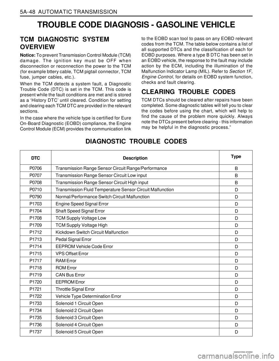
TROUBLE CODE DIAGNOSIS - GASOLINE VEHICLE
TCM DIAGNOSTIC SYSTEM
OVERVIEW
Notice: To prevent Transmission Control Module (TCM)
damage. The ignition key must be OFF when
disconnection or reconnection the power to the TCM
(for example bttery cable, TCM pigtail connector, TCM
fuse, jumper cables, etc.).
When the TCM detects a system fault, a Diagnostic
Trouble Code (DTC) is set in the TCM. This code is
present while the fault conditions are met and is stored
as a ‘History DTC’ until cleared. Condition for setting
and clearing each TCM DTC are provided in the relevant
sections.
In the case where the vehicle type is certified for Eure
On-Board Diagnostic (EOBD) compliance, the Engine
Control Module (ECM) provides the communication linkto the EOBD scan tool to pass on any EOBD relevant
codes from the TCM. The table below contains a list of
all supported DTCs and the classification of each for
EOBD purposes. Where a type B DTC has been set in
an EOBD vehicle, the response to the fault may include
action by the ECM, including the illumination of the
Malfunction lndicator Lamp (MIL). Refer to Section 1F,
Engine Control, for details on EOBD system function,
checks and fault clearing.
CLEARING TROUBLE CODES
TCM DTCs should be cleared after repairs have been
completed. Some diagnostic tables will tell you to clear
the codes before using the chart, which will help to
find the cause of the problem more quickly. Always
note the DTCs present before clearing - this information
may be helpful in the diagnostic process.”
DIAGNOSTIC TROUBLE CODES
DTC
P0706
P0707
P0708
P0710
P0790
P1703
P1704
P1708
P1709
P1712
P1713
P1714
P1715
P1717
P1718
P1719
P1720
P1721
P1722
P1733
P1734
P1735
P1736
P1737Type
B
B
B
D
D
D
D
D
D
D
D
D
D
D
D
D
D
D
D
D
D
D
D
D Description
Transmission Range Sensor Circuit Range/Performance
Transmission Range Sensor Circuit Low input
Transmission Range Sensor Circuit High input
Transmission Fluid Temperature Sensor Circuit Malfunction
Normal/Performance Switch Circuit Malfunction
Engine Speed Signal Error
Shaft Speed Signal Error
TCM Supply Voltage Low
TCM Supply Voltage High
Kickdown Switch Circuit Malfunction
Pedal Signal Error
EEPROM Vehicle Code Error
VPS Offset Error
RAM Error
ROM Error
CAN Bus Error
EEPROM Error
Throttle Signal Error
Vehicle Type Determination Error
Solenoid 1 Circuit Open
Solenoid 2 Circuit Open
Solenoid 3 Circuit Open
Solenoid 4 Circuit Open
Solenoid 5 Circuit Open
Page 1145 of 2053
5A-50 AUTOMATIC TRANSMISSION
SSANGYONG MY2002
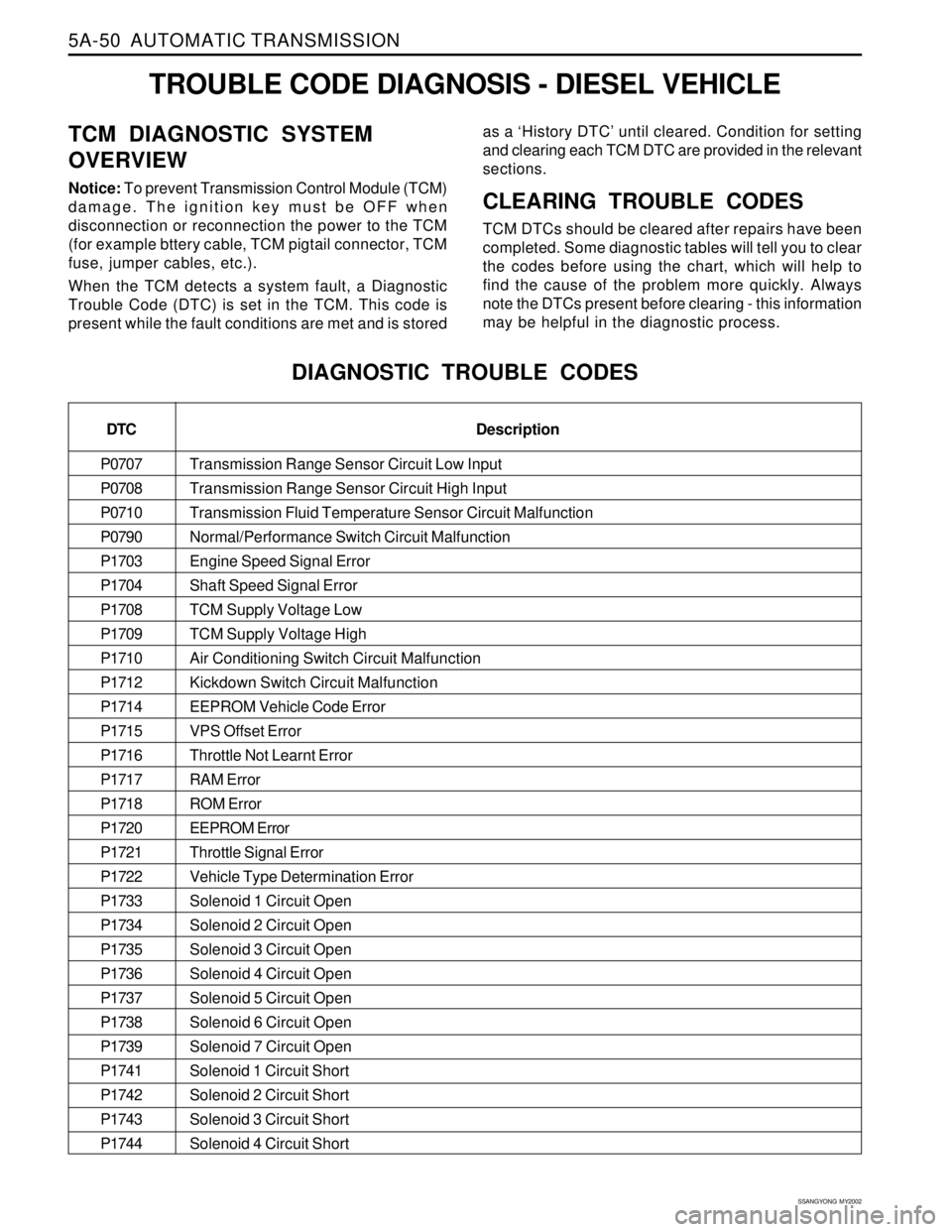
Transmission Range Sensor Circuit Low Input
Transmission Range Sensor Circuit High Input
Transmission Fluid Temperature Sensor Circuit Malfunction
Normal/Performance Switch Circuit Malfunction
Engine Speed Signal Error
Shaft Speed Signal Error
TCM Supply Voltage Low
TCM Supply Voltage High
Air Conditioning Switch Circuit Malfunction
Kickdown Switch Circuit Malfunction
EEPROM Vehicle Code Error
VPS Offset Error
Throttle Not Learnt Error
RAM Error
ROM Error
EEPROM Error
Throttle Signal Error
Vehicle Type Determination Error
Solenoid 1 Circuit Open
Solenoid 2 Circuit Open
Solenoid 3 Circuit Open
Solenoid 4 Circuit Open
Solenoid 5 Circuit Open
Solenoid 6 Circuit Open
Solenoid 7 Circuit Open
Solenoid 1 Circuit Short
Solenoid 2 Circuit Short
Solenoid 3 Circuit Short
Solenoid 4 Circuit Short
TROUBLE CODE DIAGNOSIS - DIESEL VEHICLE
TCM DIAGNOSTIC SYSTEM
OVERVIEW
Notice: To prevent Transmission Control Module (TCM)
damage. The ignition key must be OFF when
disconnection or reconnection the power to the TCM
(for example bttery cable, TCM pigtail connector, TCM
fuse, jumper cables, etc.).
When the TCM detects a system fault, a Diagnostic
Trouble Code (DTC) is set in the TCM. This code is
present while the fault conditions are met and is storedas a ‘History DTC’ until cleared. Condition for setting
and clearing each TCM DTC are provided in the relevant
sections.CLEARING TROUBLE CODES
TCM DTCs should be cleared after repairs have been
completed. Some diagnostic tables will tell you to clear
the codes before using the chart, which will help to
find the cause of the problem more quickly. Always
note the DTCs present before clearing - this information
may be helpful in the diagnostic process.
DIAGNOSTIC TROUBLE CODES
DTC
P0707
P0708
P0710
P0790
P1703
P1704
P1708
P1709
P1710
P1712
P1714
P1715
P1716
P1717
P1718
P1720
P1721
P1722
P1733
P1734
P1735
P1736
P1737
P1738
P1739
P1741
P1742
P1743
P1744Description
Page 1595 of 2053
SSANGYONG MY2002
8B-10 SUPPLEMENTAL RESTRAINTS SYSTEM
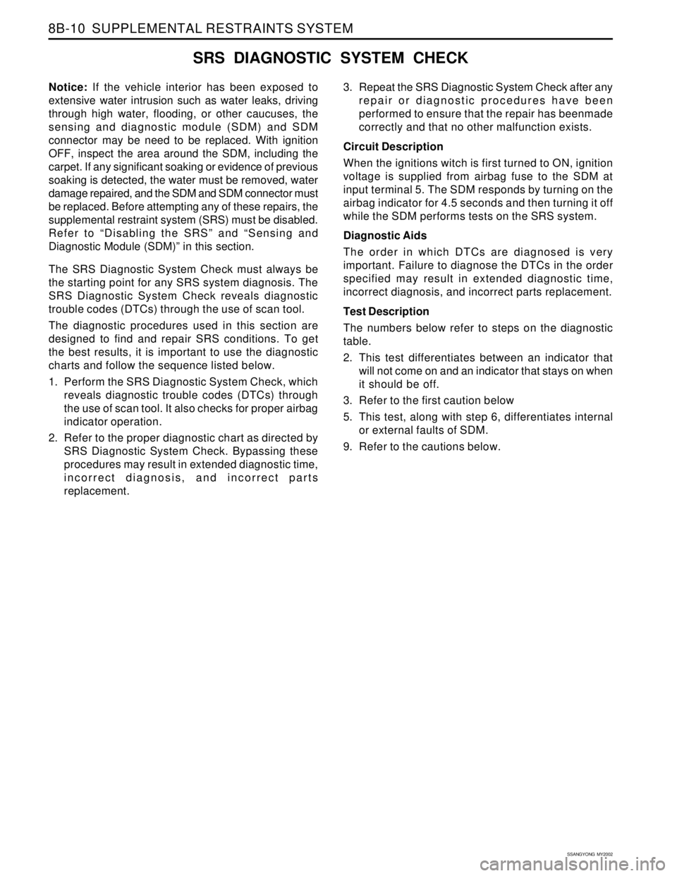
SRS DIAGNOSTIC SYSTEM CHECK
Notice: If the vehicle interior has been exposed to
extensive water intrusion such as water leaks, driving
through high water, flooding, or other caucuses, the
sensing and diagnostic module (SDM) and SDM
connector may be need to be replaced. With ignition
OFF, inspect the area around the SDM, including the
carpet. If any significant soaking or evidence of previous
soaking is detected, the water must be removed, water
damage repaired, and the SDM and SDM connector must
be replaced. Before attempting any of these repairs, the
supplemental restraint system (SRS) must be disabled.
Refer to “Disabling the SRS” and “Sensing and
Diagnostic Module (SDM)” in this section.
The SRS Diagnostic System Check must always be
the starting point for any SRS system diagnosis. The
SRS Diagnostic System Check reveals diagnostic
trouble codes (DTCs) through the use of scan tool.
The diagnostic procedures used in this section are
designed to find and repair SRS conditions. To get
the best results, it is important to use the diagnostic
charts and follow the sequence listed below.
1. Perform the SRS Diagnostic System Check, which
reveals diagnostic trouble codes (DTCs) through
the use of scan tool. It also checks for proper airbag
indicator operation.
2. Refer to the proper diagnostic chart as directed by
SRS Diagnostic System Check. Bypassing these
procedures may result in extended diagnostic time,
incorrect diagnosis, and incorrect parts
replacement.3. Repeat the SRS Diagnostic System Check after any
repair or diagnostic procedures have been
performed to ensure that the repair has beenmade
correctly and that no other malfunction exists.
Circuit Description
When the ignitions witch is first turned to ON, ignition
voltage is supplied from airbag fuse to the SDM at
input terminal 5. The SDM responds by turning on the
airbag indicator for 4.5 seconds and then turning it off
while the SDM performs tests on the SRS system.
Diagnostic Aids
The order in which DTCs are diagnosed is very
important. Failure to diagnose the DTCs in the order
specified may result in extended diagnostic time,
incorrect diagnosis, and incorrect parts replacement.
Test Description
The numbers below refer to steps on the diagnostic
table.
2. This test differentiates between an indicator that
will not come on and an indicator that stays on when
it should be off.
3. Refer to the first caution below
5. This test, along with step 6, differentiates internal
or external faults of SDM.
9. Refer to the cautions below.
Page 1596 of 2053
SUPPLEMENTAL RESTRAINTS SYSTEM 8B-11
SSANGYONG MY2002
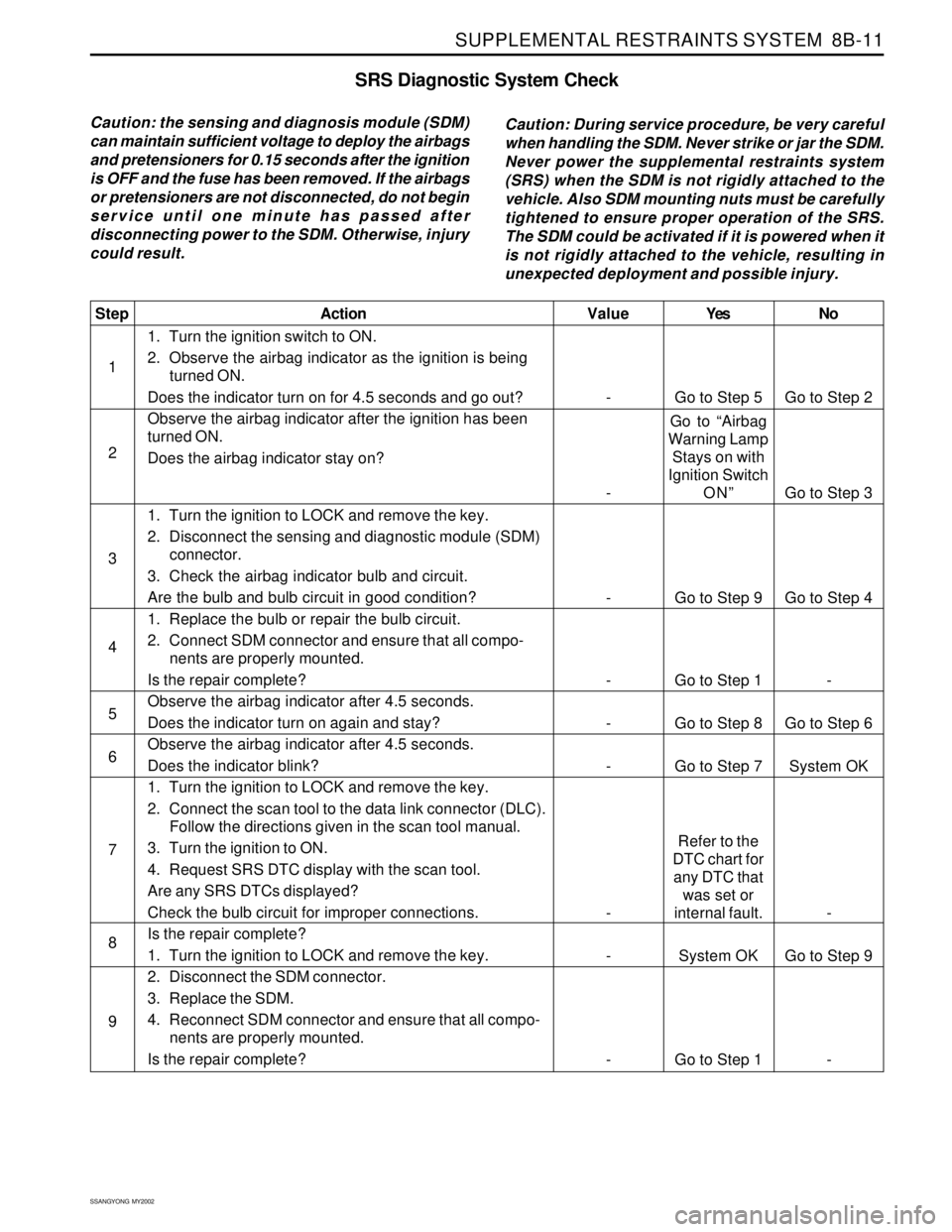
SRS Diagnostic System Check
Caution: the sensing and diagnosis module (SDM)
can maintain sufficient voltage to deploy the airbags
and pretensioners for 0.15 seconds after the ignition
is OFF and the fuse has been removed. If the airbags
or pretensioners are not disconnected, do not begin
service until one minute has passed after
disconnecting power to the SDM. Otherwise, injury
could result.Caution: During service procedure, be very careful
when handling the SDM. Never strike or jar the SDM.
Never power the supplemental restraints system
(SRS) when the SDM is not rigidly attached to the
vehicle. Also SDM mounting nuts must be carefully
tightened to ensure proper operation of the SRS.
The SDM could be activated if it is powered when it
is not rigidly attached to the vehicle, resulting in
unexpected deployment and possible injury.
Yes
Go to Step 5
Go to “Airbag
Warning Lamp
Stays on with
Ignition Switch
ON”
Go to Step 9
Go to Step 1
Go to Step 8
Go to Step 7
Refer to the
DTC chart for
any DTC that
was set or
internal fault.
System OK
Go to Step 1No
Go to Step 2
Go to Step 3
Go to Step 4
-
Go to Step 6
System OK
-
Go to Step 9
- Value
-
-
-
-
-
-
-
-
-
Step
1
2
3
4
5
6
7
8
9Action
1. Turn the ignition switch to ON.
2. Observe the airbag indicator as the ignition is being
turned ON.
Does the indicator turn on for 4.5 seconds and go out?
Observe the airbag indicator after the ignition has been
turned ON.
Does the airbag indicator stay on?
1. Turn the ignition to LOCK and remove the key.
2. Disconnect the sensing and diagnostic module (SDM)
connector.
3. Check the airbag indicator bulb and circuit.
Are the bulb and bulb circuit in good condition?
1. Replace the bulb or repair the bulb circuit.
2. Connect SDM connector and ensure that all compo-
nents are properly mounted.
Is the repair complete?
Observe the airbag indicator after 4.5 seconds.
Does the indicator turn on again and stay?
Observe the airbag indicator after 4.5 seconds.
Does the indicator blink?
1. Turn the ignition to LOCK and remove the key.
2. Connect the scan tool to the data link connector (DLC).
Follow the directions given in the scan tool manual.
3. Turn the ignition to ON.
4. Request SRS DTC display with the scan tool.
Are any SRS DTCs displayed?
Check the bulb circuit for improper connections.
Is the repair complete?
1. Turn the ignition to LOCK and remove the key.
2. Disconnect the SDM connector.
3. Replace the SDM.
4. Reconnect SDM connector and ensure that all compo-
nents are properly mounted.
Is the repair complete?
Page 1597 of 2053
SSANGYONG MY2002
8B-12 SUPPLEMENTAL RESTRAINTS SYSTEM
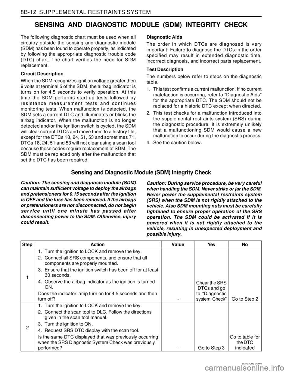
Sensing and Diagnostic Module (SDM) Integrity Check
Caution: The sensing and diagnosis module (SDM)
can maintain sufficient voltage to deploy the airbags
and pretensioners for 0.15 seconds after the ignition
is OFF and the fuse has been removed. If the airbags
or pretensioners are not disconnected, do not begin
service until one minute has passed after
disconnecting power to the SDM. Otherwise, injury
could result.Caution: During service procedure, be very careful
when handling the SDM. Never strike or jar the SDM.
Never power the supplemental restraints system
(SRS) when the SDM is not rigidly attached to the
vehicle. Also SDM mounting nuts must be carefully
tightened to ensure proper operation of the SRS
operation. The SDM could be activated if it is
powered when it is not rigidly attached to the
vehicle, resulting in unexpected deployment and
possible injury.
Yes
Chear the SRS
DTCs and go
to “Diagnostic
system Check”
Go to Step 3No
Go to Step 2
Go to table for
the DTC
indicated Value
-
-
Step
1
2Action
1. Turn the ignition to LOCK and remove the key.
2. Connect all SRS components, and ensure that all
components are properly mounted.
3. Ensure that the ignition switch has been off for at least
30 seconds.
4. Observe the airbag indicator as the ignition is turned
ON.
Does the indicator lamp turn on for 4.5 seconds and then
turn off?
1. Turn the ignition to LOCK and remove the key.
2. Connect the scan tool to DLC. Follow the directions
given in the scan tool manual.
3. Turn the ignition to ON.
4. Request SRS DTC display with the scan tool.
Is the same DTC displayed that was previously occurring
when the SRS Diagnostic System Check was previously
performed?
SENSING AND DIAGNOSTIC MODULE (SDM) INTEGRITY CHECK
The following diagnostic chart must be used when all
circuitry outside the sensing and diagnostic module
(SDM) has been found to operate properly, as indicated
by following the appropriate diagnostic trouble code
(DTC) chart. The chart verifies the need for SDM
replacement.
Circuit Description
When the SDM recognizes ignition voltage greater then
9 volts at terminal 5 of the SDM, the airbag indicator is
turns on for 4.5 seconds to verify operation. At this
time the SDM performs start-up tests followed by
resistance measurement tests and continues
monitoring tests. When malfunction is detected, the
SDM sets a current DTC and illuminates or blinks the
airbag indicator. When the malfunction is no longer
detected and/or the ignition switch is cycled, the SDM
will clear current DTCs and move them to a history file,
except for the DTCs 18, 24, 51, 53 and sometimes 71.
DTCs 18, 24, 51 and 53 will not clear using a scan tool
because these codes require replacement of SDM. The
SDM must be replaced only after the malfunction that
set the DTC has been repaired.Diagnostic Aids
The order in which DTCs are diagnosed is very
important. Failure to diagnose the DTCs in the order
specified may result in extended diagnostic time,
incorrect diagnosis, and incorrect parts replacement.
Test Description
The numbers below refer to steps on the diagnostic
table.
1. This test confirms a current malfunction. If no current
malefaction is occurring, refer to “Diagnostic Aids”
for the appropriate DTC. The SDM should not be
replaced for a historic DTC except when directed.
2. This test checks for a malfunction introduced into
the supplemental restraints system (SRS) during
the diagnostic procedure. It is extremely unlikely
that a malfunctioning SDM would cause a new
malfunction to occur during the diagnostic process.
4. See the caution below.
Page 1601 of 2053
SSANGYONG MY2002
8B-16 SUPPLEMENTAL RESTRAINTS SYSTEM
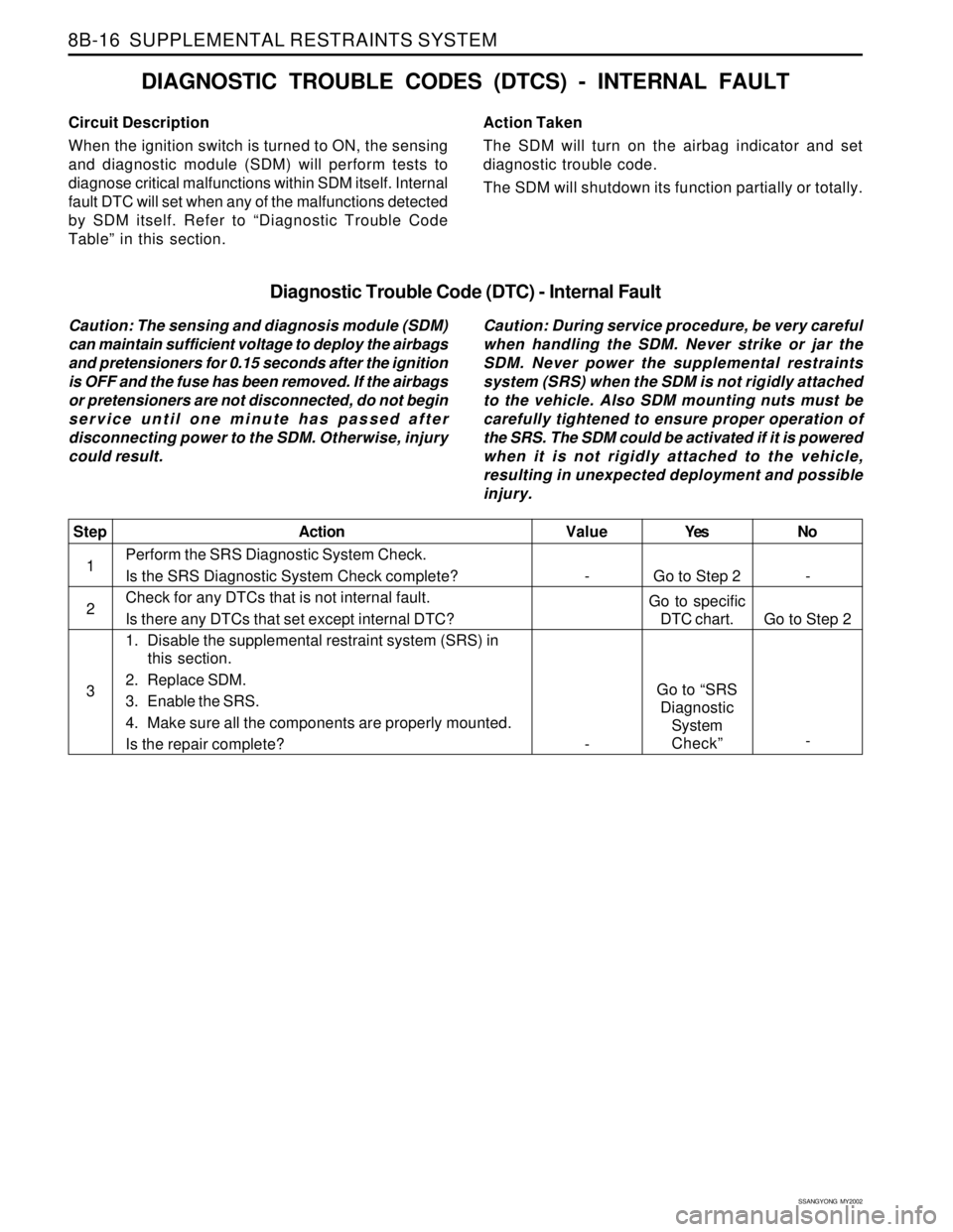
Yes
Go to Step 2
Go to specific
DTC chart.
Go to “SRS
Diagnostic
System
Check”No
-
Go to Step 2
- Value
-
-Step
1
2
3Action
Perform the SRS Diagnostic System Check.
Is the SRS Diagnostic System Check complete?
Check for any DTCs that is not internal fault.
Is there any DTCs that set except internal DTC?
1. Disable the supplemental restraint system (SRS) in
this section.
2. Replace SDM.
3. Enable the SRS.
4. Make sure all the components are properly mounted.
Is the repair complete?
Circuit Description
When the ignition switch is turned to ON, the sensing
and diagnostic module (SDM) will perform tests to
diagnose critical malfunctions within SDM itself. Internal
fault DTC will set when any of the malfunctions detected
by SDM itself. Refer to “Diagnostic Trouble Code
Table” in this section.
DIAGNOSTIC TROUBLE CODES (DTCS) - INTERNAL FAULT
Action Taken
The SDM will turn on the airbag indicator and set
diagnostic trouble code.
The SDM will shutdown its function partially or totally.
Diagnostic Trouble Code (DTC) - Internal Fault
Caution: The sensing and diagnosis module (SDM)
can maintain sufficient voltage to deploy the airbags
and pretensioners for 0.15 seconds after the ignition
is OFF and the fuse has been removed. If the airbags
or pretensioners are not disconnected, do not begin
service until one minute has passed after
disconnecting power to the SDM. Otherwise, injury
could result.Caution: During service procedure, be very careful
when handling the SDM. Never strike or jar the
SDM. Never power the supplemental restraints
system (SRS) when the SDM is not rigidly attached
to the vehicle. Also SDM mounting nuts must be
carefully tightened to ensure proper operation of
the SRS. The SDM could be activated if it is powered
when it is not rigidly attached to the vehicle,
resulting in unexpected deployment and possible
injury.
Page 1640 of 2053
SSANGYONG MY2002
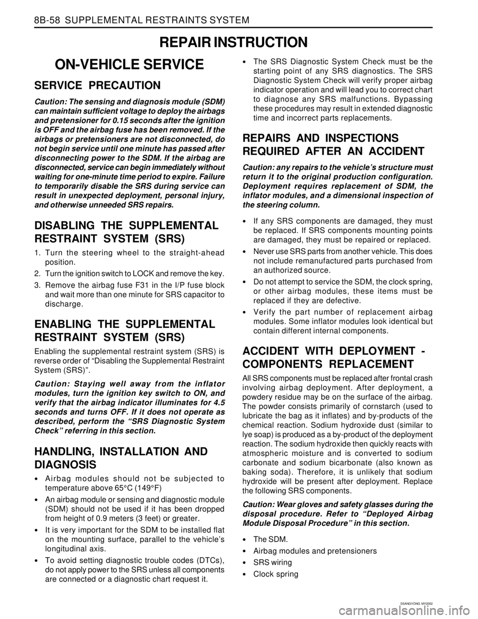
8B-58 SUPPLEMENTAL RESTRAINTS SYSTEM
REPAIR INSTRUCTION
ON-VEHICLE SERVICE
SERVICE PRECAUTION
Caution: The sensing and diagnosis module (SDM)
can maintain sufficient voltage to deploy the airbags
and pretensioner for 0.15 seconds after the ignition
is OFF and the airbag fuse has been removed. If the
airbags or pretensioners are not disconnected, do
not begin service until one minute has passed after
disconnecting power to the SDM. If the airbag are
disconnected, service can begin immediately without
waiting for one-minute time period to expire. Failure
to temporarily disable the SRS during service can
result in unexpected deployment, personal injury,
and otherwise unneeded SRS repairs.
DISABLING THE SUPPLEMENTAL
RESTRAINT SYSTEM (SRS)
1. Turn the steering wheel to the straight-ahead
position.
2. Turn the ignition switch to LOCK and remove the key.
3. Remove the airbag fuse F31 in the I/P fuse block
and wait more than one minute for SRS capacitor to
discharge.
ENABLING THE SUPPLEMENTAL
RESTRAINT SYSTEM (SRS)
Enabling the supplemental restraint system (SRS) is
reverse order of “Disabling the Supplemental Restraint
System (SRS)”.
Caution: Staying well away from the inflator
modules, turn the ignition key switch to ON, and
verify that the airbag indicator illuminates for 4.5
seconds and turns OFF. If it does not operate as
described, perform the “SRS Diagnostic System
Check” referring in this section.
HANDLING, INSTALLATION AND
DIAGNOSIS
Airbag modules should not be subjected to
temperature above 65°C (149°F)
An airbag module or sensing and diagnostic module
(SDM) should not be used if it has been dropped
from height of 0.9 meters (3 feet) or greater.
It is very important for the SDM to be installed flat
on the mounting surface, parallel to the vehicle’s
longitudinal axis.
To avoid setting diagnostic trouble codes (DTCs),
do not apply power to the SRS unless all components
are connected or a diagnostic chart request it.
The SRS Diagnostic System Check must be the
starting point of any SRS diagnostics. The SRS
Diagnostic System Check will verify proper airbag
indicator operation and will lead you to correct chart
to diagnose any SRS malfunctions. Bypassing
these procedures may result in extended diagnostic
time and incorrect parts replacements.
REPAIRS AND INSPECTIONS
REQUIRED AFTER AN ACCIDENT
Caution: any repairs to the vehicle’s structure must
return it to the original production configuration.
Deployment requires replacement of SDM, the
inflator modules, and a dimensional inspection of
the steering column.
If any SRS components are damaged, they must
be replaced. If SRS components mounting points
are damaged, they must be repaired or replaced.
Never use SRS parts from another vehicle. This does
not include remanufactured parts purchased from
an authorized source.
Do not attempt to service the SDM, the clock spring,
or other airbag modules, these items must be
replaced if they are defective.
Verify the part number of replacement airbag
modules. Some inflator modules look identical but
contain different internal components.
ACCIDENT WITH DEPLOYMENT -
COMPONENTS REPLACEMENT
All SRS components must be replaced after frontal crash
involving airbag deployment. After deployment, a
powdery residue may be on the surface of the airbag.
The powder consists primarily of cornstarch (used to
lubricate the bag as it inflates) and by-products of the
chemical reaction. Sodium hydroxide dust (similar to
lye soap) is produced as a by-product of the deployment
reaction. The sodium hydroxide then quickly reacts with
atmospheric moisture and is converted to sodium
carbonate and sodium bicarbonate (also known as
baking soda). Therefore, it is unlikely that sodium
hydroxide will be present after deployment. Replace
the following SRS components.
Caution: Wear gloves and safety glasses during the
disposal procedure. Refer to “Deployed Airbag
Module Disposal Procedure” in this section.
The SDM.
Airbag modules and pretensioners
SRS wiring
Clock spring
Page 1652 of 2053
SECTION 9A
BODY WIRING SYSTEM
CAUTION: Disconnect the negative battery cable before removing or installing any electrical unit or when a
tool or equipment could easily come in contact with exposed electrical terminals. Disconnecting this cable
will help prevent personal injury and damage to the vehicle. The ignition must also be in LOCK unless
otherwise noted.
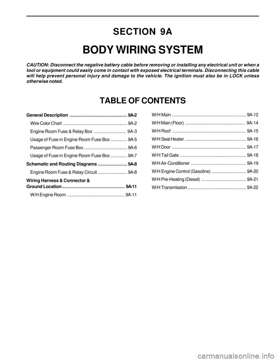
TABLE OF CONTENTS
General Description.............................................9A-2
Wire Color Chart..................................................9A-2
Engine Room Fuse & Relay Box......................... 9A-3
Usage of Fuse in Engine Room Fuse Box.............9A-5
Passenger Room Fuse Box..................................9A-6
Usage of Fuse in Engine Room Fuse Box.............9A-7
Schematic and Routing Diagrams.......................9A-8
Engine Room Fuse & Relay Circuit.......................9A-8
Wiring Harness & Connector &
Ground Location................................................. 9A-11
W/H Engine Room.............................................9A-11W/H Main..........................................................9A-12
W/H Main (Floor)............................................... 9A-14
W/H Roof..........................................................9A-15
W/H Seat Heater................................................9A-16
W/H Door..........................................................9A-17
W/H Tail Gate....................................................9A-18
W/H Air-Conditioner...........................................9A-19
W/H Engine Control (Gasoline)...........................9A-20
W/H Pre-Heating (Diesel)...................................9A-21
W/H Transmission..............................................9A-22