1997 SSANGYONG KORANDO bulb
[x] Cancel search: bulbPage 1253 of 2053
AUTOMATIC TRANSMISSION 5A-155
SSANGYONG MY2002
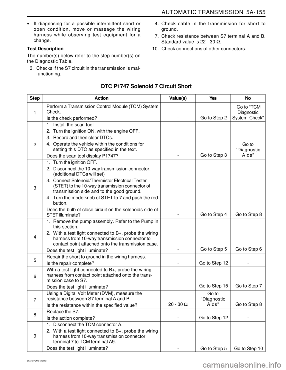
DTC P1747 Solenoid 7 Circuit Short
If diagnosing for a possible intermittent short or
open condition, move or massage the wiring
harness while observing test equipment for a
change.
Test Description
The number(s) below refer to the step number(s) on
the Diagnostic Table.
3. Checks if the S7 circuit in the transmission is mal-
functioning.4. Check cable in the transmission for short to
ground.
7. Check resistance between S7 terminal A and B.
Standard value is 22 - 30 Ω.
10. Check connections of other connectors.
- Go to Step 15 Go to Step 7 1Perform a Transmission Control Module (TCM) System
Check.
Is the check performed?
1. Install the scan tool.
2. Turn the ignition ON, with the engine OFF.
3. Record and then clear DTCs.
4. Operate the vehicle within the conditions for
setting this DTC as specified in the text.
Does the scan tool display P1747?
1. Turn the ignition OFF.
2. Disconnect the 10-way transmission connector.
(additional DTCs will set)
3. Connect Solenoid/Thermistor Electrical Tester
(STET) to the 10-way transmission connector of
transmission side and to the good ground.
4. Turn the mode knob of STET to 7 and push the red
button.
Does the bulb of close circuit on the solenoids side of
STET illuminate?
1. Remove the pump assembly. Refer to the Pump in
this section.
2. With a test light connected to B+, probe the wiring
harness from 10-way transmission connector to
contact point attached onto the transmission case.
Does the test light illuminate?
Repair the short to ground in the wiring harness.
Is the repair complete?
With a test light connected to B+, probe the wiring
harness from contact point attached onto the trans-
mission case to S7.
Does the test light illuminate?
Using a Digital Volt Meter (DVM), measure the
resistance between S7 terminal A and B.
Is the resistance within the specified value?
Replace the S7.
Is the action complete?
1. Disconnect the TCM connector A.
2. With a test light connected to B+, probe the wiring
harness from 10-way transmission connector
terminal 7 to TCM terminal A9.
Does the test light illuminate?
StepAction Value(s) Yes No
2
3
-
Go to Step 2 Go to “TCM
Diagnostic
System Check”
- Go to Step 4 Go to Step 8
5
6 4
- Go to Step 5 Go to Step 6
- Go to Step 12 -
7
8
9
- Go to Step 12 -
- Go to Step 5 Go to Step 10
- Go to Step 3Go to
“Diagnostic
Aids”
20 - 30 ΩGo to
“Diagnostic
Aids”
Go to Step 8
Page 1374 of 2053
SSANGYONG MY2002
5D1-4 TRANSFER CASE
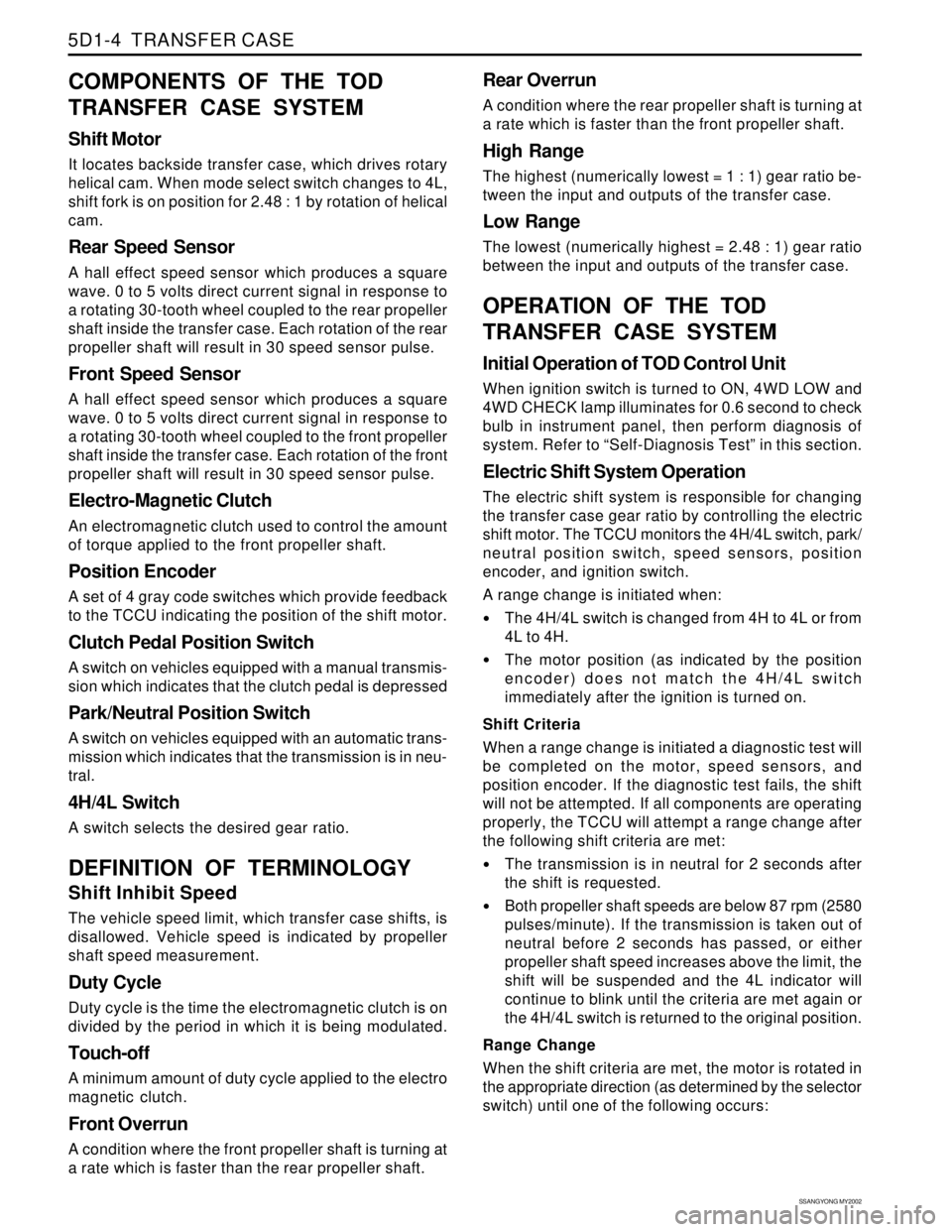
COMPONENTS OF THE TOD
TRANSFER CASE SYSTEM
Shift Motor
It locates backside transfer case, which drives rotary
helical cam. When mode select switch changes to 4L,
shift fork is on position for 2.48 : 1 by rotation of helical
cam.
Rear Speed Sensor
A hall effect speed sensor which produces a square
wave. 0 to 5 volts direct current signal in response to
a rotating 30-tooth wheel coupled to the rear propeller
shaft inside the transfer case. Each rotation of the rear
propeller shaft will result in 30 speed sensor pulse.
Front Speed Sensor
A hall effect speed sensor which produces a square
wave. 0 to 5 volts direct current signal in response to
a rotating 30-tooth wheel coupled to the front propeller
shaft inside the transfer case. Each rotation of the front
propeller shaft will result in 30 speed sensor pulse.
Electro-Magnetic Clutch
An electromagnetic clutch used to control the amount
of torque applied to the front propeller shaft.
Position Encoder
A set of 4 gray code switches which provide feedback
to the TCCU indicating the position of the shift motor.
Clutch Pedal Position Switch
A switch on vehicles equipped with a manual transmis-
sion which indicates that the clutch pedal is depressed
Park/Neutral Position Switch
A switch on vehicles equipped with an automatic trans-
mission which indicates that the transmission is in neu-
tral.
4H/4L Switch
A switch selects the desired gear ratio.
DEFINITION OF TERMINOLOGY
Shift Inhibit Speed
The vehicle speed limit, which transfer case shifts, is
disallowed. Vehicle speed is indicated by propeller
shaft speed measurement.
Duty Cycle
Duty cycle is the time the electromagnetic clutch is on
divided by the period in which it is being modulated.
Touch-off
A minimum amount of duty cycle applied to the electro
magnetic clutch.
Front Overrun
A condition where the front propeller shaft is turning at
a rate which is faster than the rear propeller shaft.
Rear Overrun
A condition where the rear propeller shaft is turning at
a rate which is faster than the front propeller shaft.
High Range
The highest (numerically lowest = 1 : 1) gear ratio be-
tween the input and outputs of the transfer case.
Low Range
The lowest (numerically highest = 2.48 : 1) gear ratio
between the input and outputs of the transfer case.
OPERATION OF THE TOD
TRANSFER CASE SYSTEM
Initial Operation of TOD Control Unit
When ignition switch is turned to ON, 4WD LOW and
4WD CHECK lamp illuminates for 0.6 second to check
bulb in instrument panel, then perform diagnosis of
system. Refer to “Self-Diagnosis Test” in this section.
Electric Shift System Operation
The electric shift system is responsible for changing
the transfer case gear ratio by controlling the electric
shift motor. The TCCU monitors the 4H/4L switch, park/
neutral position switch, speed sensors, position
encoder, and ignition switch.
A range change is initiated when:
The 4H/4L switch is changed from 4H to 4L or from
4L to 4H.
The motor position (as indicated by the position
encoder) does not match the 4H/4L switch
immediately after the ignition is turned on.
Shift Criteria
When a range change is initiated a diagnostic test will
be completed on the motor, speed sensors, and
position encoder. If the diagnostic test fails, the shift
will not be attempted. If all components are operating
properly, the TCCU will attempt a range change after
the following shift criteria are met:
The transmission is in neutral for 2 seconds after
the shift is requested.
Both propeller shaft speeds are below 87 rpm (2580
pulses/minute). If the transmission is taken out of
neutral before 2 seconds has passed, or either
propeller shaft speed increases above the limit, the
shift will be suspended and the 4L indicator will
continue to blink until the criteria are met again or
the 4H/4L switch is returned to the original position.
Range Change
When the shift criteria are met, the motor is rotated in
the appropriate direction (as determined by the selector
switch) until one of the following occurs:
Page 1384 of 2053
SSANGYONG MY2002
5D1-14 TRANSFER CASE
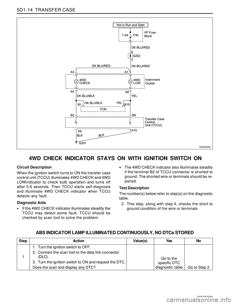
4WD CHECK INDICATOR STAYS ON WITH IGNITION SWITCH ON
KAA5D040
Circuit Description
When the ignition switch turns to ON the transfer case
control unit (TCCU) illuminates 4WD CHECK and 4WD
LOWindicator to check bulb operation and turns off
after 0.6 seconds. Then TCCU starts self-diagnosis
and illuminate 4WD CHECK indicator when TCCU
detects any fault.
Diagnostic Aids
If the 4WD CHECK indicator illuminates steadily the
TCCU may detect some fault. TCCU should be
checked by scan tool to solve the problem.
The 4WD CHECK indicator also illuminates steadily
if the terminal B2 of TCCU connector is shorted to
ground. The shorted wire or terminals should be re-
paired.
Test Description
The number(s) below refer to step(s) on the diagnostic
table.
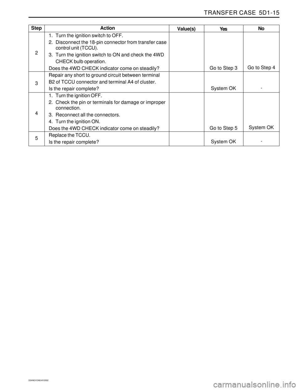
2. This step, along with step 4, checks the short to
ground condition of the wire or terminals
Step
1
ABS INDICATOR LAMP ILLUMINATED CONTINUOUSLY, NO DTCs STORED
Action Yes
Go to the
specific DTC
diagnostic tableNo
Go to Step 2 Value(s)
1. Turn the ignition switch to OFF.
2. Connect the scan tool to the data link connector
(DLC).
3. Turn the ignition switch to ON and request the DTC.
Does the scan tool display any DTC?
Page 1385 of 2053
TRANSFER CASE 5D1-15
SSANGYONG MY2002
Step
2
3
4
5Action
Yes
Go to Step 3
System OK
Go to Step 5
System OKNo
Go to Step 4
-
System OK
- Value(s)
1. Turn the ignition switch to OFF.
2. Disconnect the 18-pin connector from transfer case
control unit (TCCU).
3. Turn the ignition switch to ON and check the 4WD
CHECK bulb operation.
Does the 4WD CHECK indicator come on steadily?
Repair any short to ground circuit between terminal
B2 of TCCU connector and terminal A4 of cluster.
Is the repair complete?
1. Turn the ignition OFF.
2. Check the pin or terminals for damage or improper
connection.
3. Reconnect all the connectors.
4. Turn the ignition ON.
Does the 4WD CHECK indicator come on steadily?
Replace the TCCU.
Is the repair complete?
Page 1386 of 2053
SSANGYONG MY2002
5D1-16 TRANSFER CASE
KAA5D040
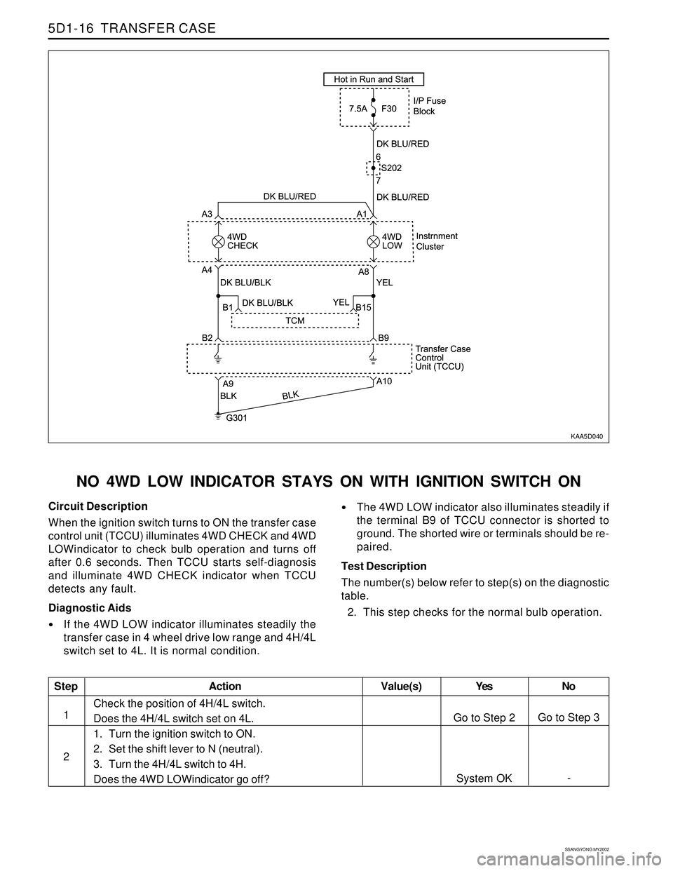
NO 4WD LOW INDICATOR STAYS ON WITH IGNITION SWITCH ON
Circuit Description
When the ignition switch turns to ON the transfer case
control unit (TCCU) illuminates 4WD CHECK and 4WD
LOWindicator to check bulb operation and turns off
after 0.6 seconds. Then TCCU starts self-diagnosis
and illuminate 4WD CHECK indicator when TCCU
detects any fault.
Diagnostic Aids
If the 4WD LOW indicator illuminates steadily the
transfer case in 4 wheel drive low range and 4H/4L
switch set to 4L. It is normal condition.
The 4WD LOW indicator also illuminates steadily if
the terminal B9 of TCCU connector is shorted to
ground. The shorted wire or terminals should be re-
paired.
Test Description
The number(s) below refer to step(s) on the diagnostic
table.
2. This step checks for the normal bulb operation.
Step
1
2
Action Yes
Go to Step 2
System OKNo
Go to Step 3
- Value(s)
Check the position of 4H/4L switch.
Does the 4H/4L switch set on 4L.
1. Turn the ignition switch to ON.
2. Set the shift lever to N (neutral).
3. Turn the 4H/4L switch to 4H.
Does the 4WD LOWindicator go off?
Page 1420 of 2053
TRANSFER CASE (PART TIME - 4408) 5D2-21
SSANGYONG MY2002
KAA5D240
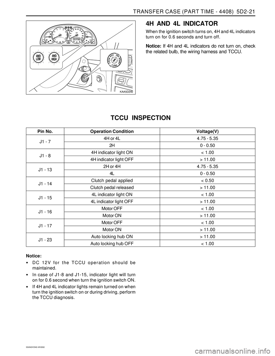
4H AND 4L INDICATOR
When the ignition switch turns on, 4H and 4L indicators
turn on for 0.6 seconds and turn off.
Notice: If 4H and 4L indicators do not turn on, check
the related bulb, the wiring harness and TCCU.
J1 - 7
J1 - 8
J1 - 13
J1 - 14
J1 - 15
J1 - 16
J1 - 17
J1 - 234H or 4L
2H
4H indicator light ON
4H indicator light OFF
2H or 4H
4L
Clutch pedal applied
Clutch pedal released
4L indicator light ON
4L indicator light OFF
Motor OFF
Motor ON
Motor OFF
Motor ON
Auto locking hub ON
Auto locking hub OFF
TCCU INSPECTION
4.75 - 5.35
0 - 0.50
< 1.00
> 11.00
4.75 - 5.35
0 - 0.50
< 0.50
> 11.00
< 1.00
> 11.00
< 1.00
> 11.00
< 1.00
> 11.00
> 11.00
< 1.00
Pin No. Voltage(V)Operation Condition
Notice:
DC 12V for the TCCU operation should be
maintained.
In case of J1-8 and J1-15, indicator light will turn
on for 0.6 second when turn the ignition switch ON.
If 4H and 4L indicator lights remain turned on when
turn the ignition switch on or during driving, perform
the TCCU diagnosis.
Page 1520 of 2053
HEATING AND VENTILATION SYSTEM 7A-19
SSANGYONG MY2002
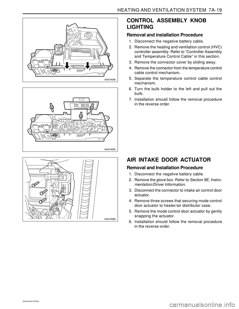
CONTROL ASSEMBLY KNOB
LIGHTING
Removal and installation Procedure
1. Disconnect the negative battery cable.
2. Remove the heating and ventilation control (HVC)
controller assembly. Refer to “Controller Assembly
and Temperature Control Cable” in this section.
3. Remove the connector cover by sliding away.
4. Remove the connector from the temperature control
cable control mechanism.
5. Separate the temperature control cable control
mechanism.
6. Turn the bulb holder to the left and pull out the
bulb.
7. Installation should follow the removal procedure
in the reverse order.
KAA7A040
KAA7A050
KAA7A060
AIR INTAKE DOOR ACTUATOR
Removal and Installation Procedure
1. Disconnect the negative battery cable.
2. Remove the glove box. Refer to Section 9E, Instru-
mentation/Driver Information.
3. Disconnect the connector to intake air control door
actuator.
4. Remove three screws that securing mode control
door actuator to heater/air distributor case.
5. Remove the mode control door actuator by gently
snapping the actuator.
6. Installation should follow the removal procedure
in the reverse order.
Page 1546 of 2053
MANUAL & SEMIAUTO-HVAC 7C-17
SSANGYONG MY2002
����� �����
�����
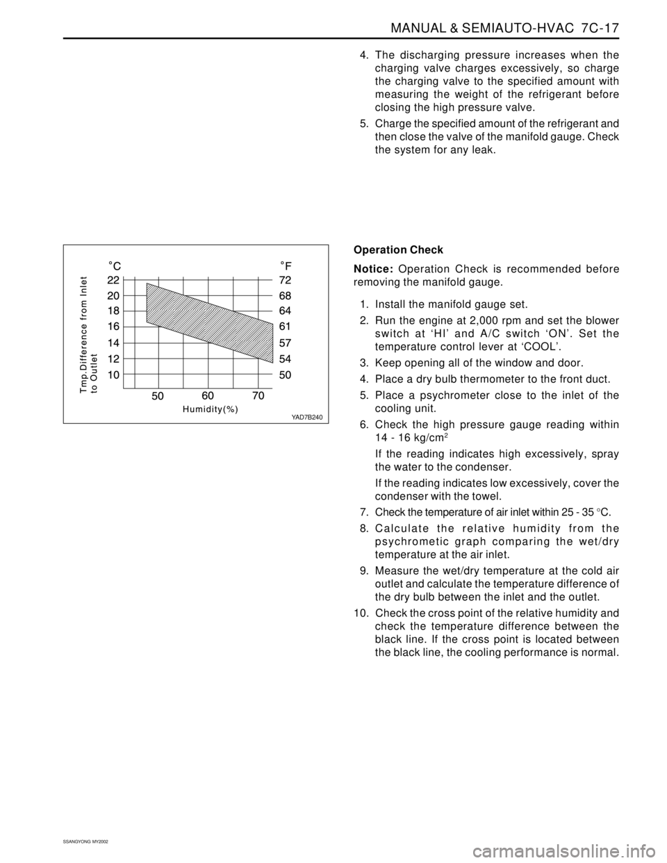
Operation Check
Notice: Operation Check is recommended before
removing the manifold gauge.
1. Install the manifold gauge set.
2. Run the engine at 2,000 rpm and set the blower
switch at ‘HI’ and A/C switch ‘ON’. Set the
temperature control lever at ‘COOL’.
3. Keep opening all of the window and door.
4. Place a dry bulb thermometer to the front duct.
5. Place a psychrometer close to the inlet of the
cooling unit.
6. Check the high pressure gauge reading within
14 - 16 kg/cm
2
If the reading indicates high excessively, spray
the water to the condenser.
If the reading indicates low excessively, cover the
condenser with the towel.
7. Check the temperature of air inlet within 25 - 35 °C.
8. Calculate the relative humidity from the
psychrometic graph comparing the wet/dry
temperature at the air inlet.
9. Measure the wet/dry temperature at the cold air
outlet and calculate the temperature difference of
the dry bulb between the inlet and the outlet.
10. Check the cross point of the relative humidity and
check the temperature difference between the
black line. If the cross point is located between
the black line, the cooling performance is normal.
4. The discharging pressure increases when the
charging valve charges excessively, so charge
the charging valve to the specified amount with
measuring the weight of the refrigerant before
closing the high pressure valve.
5. Charge the specified amount of the refrigerant and
then close the valve of the manifold gauge. Check
the system for any leak.
YAD7B240