1997 SSANGYONG KORANDO alternator
[x] Cancel search: alternatorPage 19 of 2053

GENERAL INFORMATION 0B -- 19
D AEW OO M Y_2000
Gasolind Engine NumberDiesel Engine Number
Engine Number Location
Diesel Engine
The engine number is stamped on the cylinder block in
front of injection pump.
IL6 3200 Gasolind Engine
The engine number is stamped on the lower rear side of
the alternator.
Page 761 of 2053

OM600 ENGINE ELECTRICAL 1E3 -- 7
D AEW OO M Y_2000
Removal & Installation Procedure
1. Disconnect the negative terminal of the battery.
2. Disconnect the plug connection (5).
3. OM 662 Engine
Align the groove of cooling fan with bolt (2) (arrow).
4. Remove the bolts (2, 3) and take out the alternator.
Tightening Torque45 N∙m (33 lb-ft)
5. Installation should follow the removal procedure in
the reverse order.
Page 1656 of 2053
BODY WIRING SYSTEM 9A-5
SSANGYONG MY2002
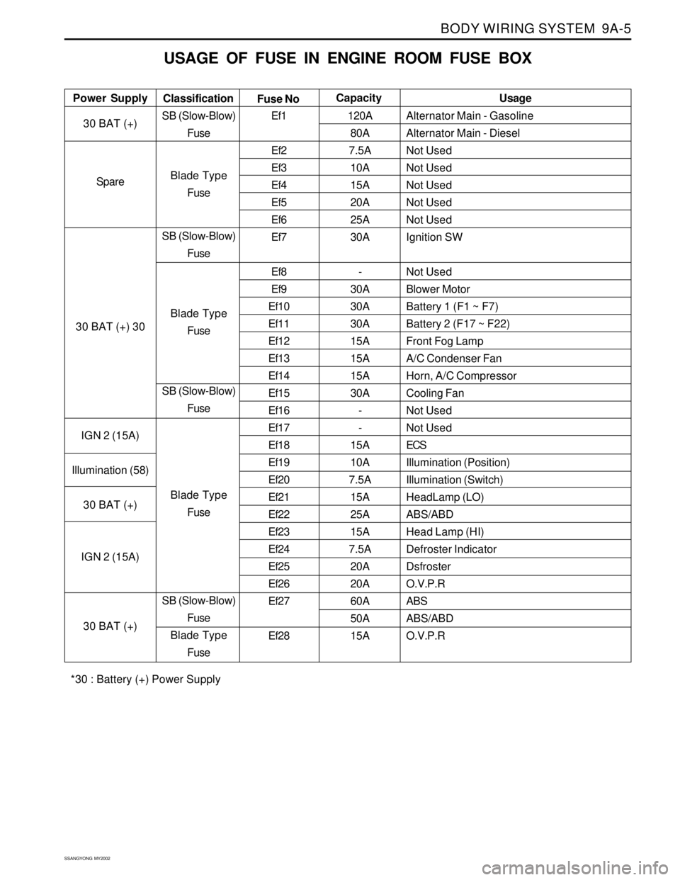
USAGE OF FUSE IN ENGINE ROOM FUSE BOX
Alternator Main - Gasoline
Alternator Main - Diesel
Not Used
Not Used
Not Used
Not Used
Not Used
Ignition SW
Not Used
Blower Motor
Battery 1 (F1 ~ F7)
Battery 2 (F17 ~ F22)
Front Fog Lamp
A/C Condenser Fan
Horn, A/C Compressor
Cooling Fan
Not Used
Not Used
ECS
Illumination (Position)
Illumination (Switch)
HeadLamp (LO)
ABS/ABD
Head Lamp (HI)
Defroster Indicator
Dsfroster
O.V.P.R
ABS
ABS/ABD
O.V.P.R Power SupplyUsage
Classification
Fuse NoCapacity
30 BAT (+)
Spare
30 BAT (+) 30
IGN 2 (15A)
Illumination (58)
30 BAT (+)
IGN 2 (15A)
30 BAT (+)SB (Slow-Blow)
Fuse
Blade Type
Fuse
SB (Slow-Blow)
Fuse
Blade Type
Fuse
SB (Slow-Blow)
Fuse
Blade Type
Fuse
SB (Slow-Blow)
Fuse
Blade Type
FuseEf1
Ef2
Ef3
Ef4
Ef5
Ef6
Ef7
Ef8
Ef9
Ef10
Ef11
Ef12
Ef13
Ef14
Ef15
Ef16
Ef17
Ef18
Ef19
Ef20
Ef21
Ef22
Ef23
Ef24
Ef25
Ef26
Ef27
Ef28120A
80A
7.5A
10A
15A
20A
25A
30A
-
30A
30A
30A
15A
15A
15A
30A
-
-
15A
10A
7.5A
15A
25A
15A
7.5A
20A
20A
60A
50A
15A
*30 : Battery (+) Power Supply
Page 1662 of 2053
BODY WIRING SYSTEM 9A-11
SSANGYONG MY2002
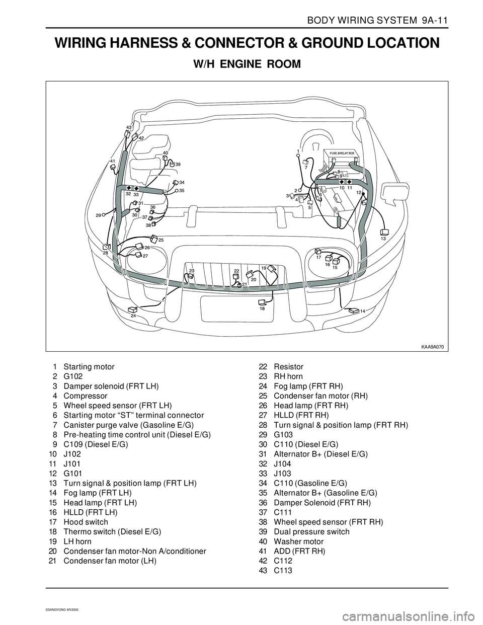
WIRING HARNESS & CONNECTOR & GROUND LOCATION
W/H ENGINE ROOM
KAA9A070
1 Starting motor
2 G102
3 Damper solenoid (FRT LH)
4 Compressor
5 Wheel speed sensor (FRT LH)
6 Starting motor “ST” terminal connector
7 Canister purge valve (Gasoline E/G)
8 Pre-heating time control unit (Diesel E/G)
9 C109 (Diesel E/G)
10 J102
11 J101
12 G101
13 Turn signal & position lamp (FRT LH)
14 Fog lamp (FRT LH)
15 Head lamp (FRT LH)
16 HLLD (FRT LH)
17 Hood switch
18 Thermo switch (Diesel E/G)
19 LH horn
20 Condenser fan motor-Non A/conditioner
21 Condenser fan motor (LH)22 Resistor
23 RH horn
24 Fog lamp (FRT RH)
25 Condenser fan motor (RH)
26 Head lamp (FRT RH)
27 HLLD (FRT RH)
28 Turn signal & position lamp (FRT RH)
29 G103
30 C110 (Diesel E/G)
31 Alternator B+ (Diesel E/G)
32 J104
33 J103
34 C110 (Gasoline E/G)
35 Alternator B+ (Gasoline E/G)
36 Damper Solenoid (FRT RH)
37 C111
38 Wheel speed sensor (FRT RH)
39 Dual pressure switch
40 Washer motor
41 ADD (FRT RH)
42 C112
43 C113
Page 1726 of 2053
INSTRUMENTATION, DRIVER INFORMATION 9E-9
SSANGYONG MY2002
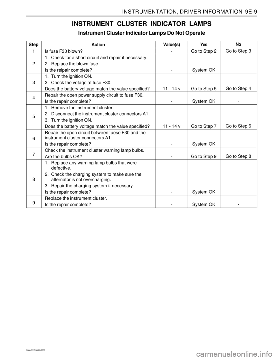
INSTRUMENT CLUSTER INDICATOR LAMPS
Instrument Cluster Indicator Lamps Do Not Operate
Step
1
2
3
4
5
6
7
8
9Action
Is fuse F30 blown?
1. Check for a short circuit and repair if necessary.
2. Replace the blown fuse.
Is the relpair complete?
1. Turn the ignition ON.
2. Check the votage at fuse F30.
Does the battery voltage match the value specified?
Repair the open power supply circuit to fuse F30.
Is the repair complete?
1. Remove the instrument cluster.
2. Disconnect the instrument cluster connectors A1.
3. Turn the ignition ON.
Does the battery voltage match the value specified?
Repair the open circuit between fuese F30 and the
instrument cluster connectors A1.
Is the repair complete?
Check the instrument cluster warning lamp bulbs.
Are the bulbs OK?
1. Replace any warning lamp bulbs that were
defective.
2. Check the charging system to make sure the
alternator is not overcharging.
3. Repair the charging system if necessary.
Is the repair complete?
Replace the instrument cluster.
Is the repair complete?Yes
Go to Step 2
System OK
Go to Step 5
System OK
Go to Step 7
System OK
Go to Step 9
System OK
System OKNo
Go to Step 3
-
Go to Step 4
-
Go to Step 6
-
Go to Step 8
-
- Value(s)
-
-
11 - 14 v
-
11 - 14 v
-
-
-
-
Page 1868 of 2053
2-4 2-4 2-4 2-4
2-4
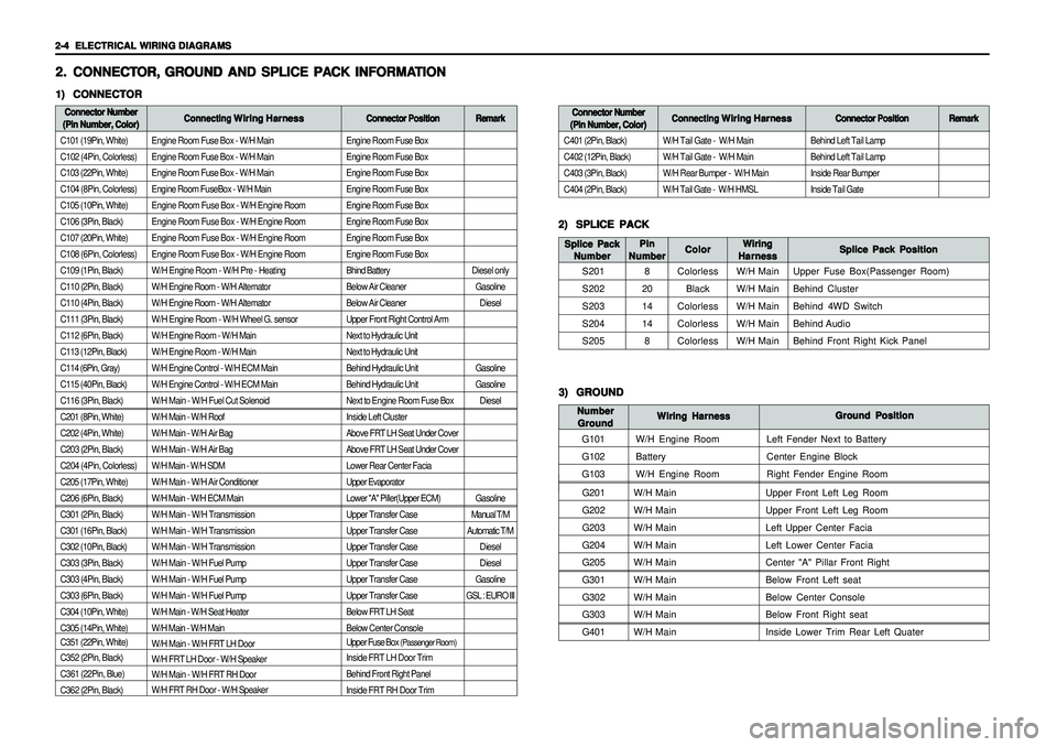
ELECTRICAL WIRING DIAGRAMS ELECTRICAL WIRING DIAGRAMSELECTRICAL WIRING DIAGRAMS ELECTRICAL WIRING DIAGRAMS
ELECTRICAL WIRING DIAGRAMS
Engine Room Fuse Box - W/H Main
Engine Room Fuse Box - W/H Main
Engine Room Fuse Box - W/H Main
Engine Room FuseBox - W/H Main
Engine Room Fuse Box - W/H Engine Room
Engine Room Fuse Box - W/H Engine Room
Engine Room Fuse Box - W/H Engine Room
Engine Room Fuse Box - W/H Engine Room
W/H Engine Room - W/H Pre - Heating
W/H Engine Room - W/H Alternator
W/H Engine Room - W/H Alternator
W/H Engine Room - W/H Wheel G. sensor
W/H Engine Room - W/H Main
W/H Engine Room - W/H Main
W/H Engine Control - W/H ECM Main
W/H Engine Control - W/H ECM Main
W/H Main - W/H Fuel Cut Solenoid
W/H Main - W/H Roof
W/H Main - W/H Air Bag
W/H Main - W/H Air Bag
W/H Main - W/H SDM
W/H Main - W/H Air Conditioner
W/H Main - W/H ECM Main
W/H Main - W/H Transmission
W/H Main - W/H Transmission
W/H Main - W/H Transmission
W/H Main - W/H Fuel Pump
W/H Main - W/H Fuel Pump
W/H Main - W/H Fuel Pump
W/H Main - W/H Seat Heater
W/H Main - W/H Main
W/H Main - W/H FRT LH Door
W/H FRT LH Door - W/H Speaker
W/H Main - W/H FRT RH Door
W/H FRT RH Door - W/H Speaker
G201W/H Main Upper Front Left Leg Room
G202W/H Main Upper Front Left Leg Room
G203W/H Main Left Upper Center Facia
G204W/H Main Left Lower Center Facia
G205W/H Main Center "A" Pillar Front Right
G301W/H Main Below Front Left seat
G302W/H Main Below Center Console
G303W/H Main Below Front Right seat
G401W/H Main Inside Lower Trim Rear Left Quater
Engine Room Fuse Box
Engine Room Fuse Box
Engine Room Fuse Box
Engine Room Fuse Box
Engine Room Fuse Box
Engine Room Fuse Box
Engine Room Fuse Box
Engine Room Fuse Box
Bhind Battery
Below Air Cleaner
Below Air Cleaner
Upper Front Right Control Arm
Next to Hydraulic Unit
Next to Hydraulic Unit
Behind Hydraulic Unit
Behind Hydraulic Unit
Next to Engine Room Fuse Box
Inside Left Cluster
Above FRT LH Seat Under Cover
Above FRT LH Seat Under Cover
Lower Rear Center Facia
Upper Evaporator
Lower "A" Piller(Upper ECM)
Upper Transfer Case
Upper Transfer Case
Upper Transfer Case
Upper Transfer Case
Upper Transfer Case
Upper Transfer Case
Below FRT LH Seat
Below Center Console
Upper Fuse Box
(Passenger Room)
Inside FRT LH Door Trim
Behind Front Right Panel
Inside FRT RH Door Trim
2. 2.2. 2.
2.
CONNECT CONNECTCONNECT CONNECT
CONNECT
OR, OR,OR, OR,
OR,
GR GR GR GR
GR
OUND AND SPLICE PA OUND AND SPLICE PAOUND AND SPLICE PA OUND AND SPLICE PA
OUND AND SPLICE PA
CK INFORMA CK INFORMACK INFORMA CK INFORMA
CK INFORMA
TION TIONTION TION
TION1) 1)1) 1)
1)
CONNECTOR CONNECTORCONNECTOR CONNECTOR
CONNECTORConnector Number Connector NumberConnector Number Connector Number
Connector Number
(Pin Number, Color) (Pin Number, Color)(Pin Number, Color) (Pin Number, Color)
(Pin Number, Color)Connecting Connecting Connecting Connecting
Connecting
Wiring Harness Wiring HarnessWiring Harness Wiring Harness
Wiring Harness
Connector Position Connector PositionConnector Position Connector Position
Connector Position
C101 (19Pin, White)
C102 (4Pin, Colorless)
C103 (22Pin, White)
C104 (8Pin, Colorless)
C105 (10Pin, White)
C106 (3Pin, Black)
C107 (20Pin, White)
C108 (6Pin, Colorless)
C109 (1Pin, Black)
C110 (2Pin, Black)
C110 (4Pin, Black)
C111 (3Pin, Black)
C112 (6Pin, Black)
C113 (12Pin, Black)
C114 (6Pin, Gray)
C115 (40Pin, Black)
C116 (3Pin, Black)
C201 (8Pin, White)
C202 (4Pin, White)
C203 (2Pin, Black)
C204 (4Pin, Colorless)
C205 (17Pin, White)
C206 (6Pin, Black)
C301 (2Pin, Black)
C301 (16Pin, Black)
C302 (10Pin, Black)
C303 (3Pin, Black)
C303 (4Pin, Black)
C303 (6Pin, Black)
C304 (10Pin, White)
C305 (14Pin, White)
C351 (22Pin, White)
C352 (2Pin, Black)
C361 (22Pin, Blue)
C362 (2Pin, Black)
2) 2)2) 2)
2)
SPLICE PACK SPLICE PACKSPLICE PACK SPLICE PACK
SPLICE PACK
S201
S202
S203
S204
S205Splice Pack Position Splice Pack PositionSplice Pack Position Splice Pack Position
Splice Pack Position Wiring WiringWiring Wiring
Wiring
Harness HarnessHarness Harness
Harness Color ColorColor Color
Color Splice Pack Splice PackSplice Pack Splice Pack
Splice Pack
Number NumberNumber Number
Number
Colorless
Black
Colorless
Colorless
ColorlessW/H Main
W/H Main
W/H Main
W/H Main
W/H MainUpper Fuse Box(Passenger Room)
Behind Cluster
Behind 4WD Switch
Behind Audio
Behind Front Right Kick Panel
Remark RemarkRemark Remark
Remark
Diesel only
Gasoline
Diesel
Gasoline
Gasoline
Diesel
Gasoline
Manual T/M
Automatic T/M
Diesel
Diesel
Gasoline
GSL : EURO IIIBehind Left Tail Lamp
Behind Left Tail Lamp
Inside Rear Bumper
Inside Tail Gate
Connector Number Connector NumberConnector Number Connector Number
Connector Number
(Pin Number, Color) (Pin Number, Color)(Pin Number, Color) (Pin Number, Color)
(Pin Number, Color)Connecting Connecting Connecting Connecting
Connecting
Wiring Harness Wiring HarnessWiring Harness Wiring Harness
Wiring Harness
Connector Position Connector PositionConnector Position Connector Position
Connector Position
C401 (2Pin, Black)
C402 (12Pin, Black)
C403 (3Pin, Black)
C404 (2Pin, Black)W/H Tail Gate - W/H Main
W/H Tail Gate - W/H Main
W/H Rear Bumper - W/H Main
W/H Tail Gate - W/H HMSL
Remark RemarkRemark Remark
Remark
3) 3)3) 3)
3)
GROUND GROUNDGROUND GROUND
GROUND
G101
G102
G103Ground Position Ground PositionGround Position Ground Position
Ground Position
Wiring Harness Wiring HarnessWiring Harness Wiring Harness
Wiring Harness Number NumberNumber Number
Number
Ground GroundGround Ground
Ground
W/H Engine Room
Battery
W/H Engine RoomLeft Fender Next to Battery
Center Engine Block
Right Fender Engine Room
Pin PinPin Pin
Pin
Number NumberNumber Number
Number
8
20
14
14
8
Page 1870 of 2053
2-6 2-6 2-6 2-6
2-6
ELECTRICAL WIRING DIAGRAMS ELECTRICAL WIRING DIAGRAMSELECTRICAL WIRING DIAGRAMS ELECTRICAL WIRING DIAGRAMS
ELECTRICAL WIRING DIAGRAMS3. 3.3. 3.
3.
WIRING HARNESS & CONNECT WIRING HARNESS & CONNECTWIRING HARNESS & CONNECT WIRING HARNESS & CONNECT
WIRING HARNESS & CONNECT
OR & GR OR & GROR & GR OR & GR
OR & GR
OUND LOCA OUND LOCAOUND LOCA OUND LOCA
OUND LOCA
TION TIONTION TION
TION1) 1)1) 1)
1)
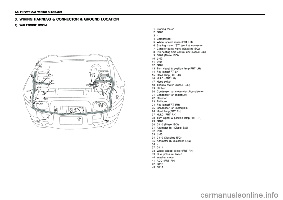
W/H ENGINE ROOM W/H ENGINE ROOMW/H ENGINE ROOM W/H ENGINE ROOM
W/H ENGINE ROOM
1. Starting motor
2. G102
3. -
4. Compressor
5. Wheel speed sensor(FRT LH)
6. Starting motor "ST" terminal connector
7. Canister purge valve (Gasoline E/G)
8. Pre-heating time control unit (Diesel E/G)
9. C109 (Diesel E/G)
10. J102
11. J101
12. G101
13. Turn signal & position lamp(FRT LH)
14. Fog lamp(FRT LH)
15. Head lamp(FRT LH)
16. HLLD (FRT LH)
17. Hood switch
18. Thermo switch (Diesel E/G)
19. LH horn
20. Condenser fan motor-Non A/conditioner
21. Condenser fan motor(LH)
22. Resistor
23. RH horn
24. Fog lamp(FRT RH)
25. Condenser fan motor(RH)
26. Head lamp(FRT RH)
27. HLLD (FRT RH)
28. Turn signal & position lamp(FRT RH)
29. G103
30. C110 (Diesel E/G)
31. Alternator B+ (Diesel E/G)
32. J104
33. J103
34. C110 (Gasoline E/G)
35. Alternator B+ (Gasoline E/G)
36. -
37. C111
38. Wheel speed sensor(FRT RH)
39. Dual pressure switch
40. Washer motor
41. ADD (FRT RH)
42. C112
43. C113
FUSE &RELAY BOX
42
43
41
40
393435
37303138
2928
25
26
24
23
2221201918
17
1516
13
12111089
7
6
5
4321
14
27
3233
Page 1892 of 2053
4-2 4-2 4-2 4-2
4-2
USAGE AND CAPACITY OF FUSES IN FUSE BOX USAGE AND CAPACITY OF FUSES IN FUSE BOXUSAGE AND CAPACITY OF FUSES IN FUSE BOX USAGE AND CAPACITY OF FUSES IN FUSE BOX
USAGE AND CAPACITY OF FUSES IN FUSE BOX1. 1.1. 1.
1.
ENGINE ROOM FUSE & RELA ENGINE ROOM FUSE & RELAENGINE ROOM FUSE & RELA ENGINE ROOM FUSE & RELA
ENGINE ROOM FUSE & RELA
Y BO Y BOY BO Y BO
Y BO
X XX X
X1) 1)1) 1)
1)
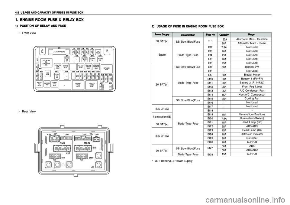
POSITION OF RELAY AND FUSE POSITION OF RELAY AND FUSEPOSITION OF RELAY AND FUSE POSITION OF RELAY AND FUSE
POSITION OF RELAY AND FUSE
• Front View
Rear View2) 2)2) 2)
2)
USAGE OF FUSE IN ENGINE ROOM FUSE BOX USAGE OF FUSE IN ENGINE ROOM FUSE BOXUSAGE OF FUSE IN ENGINE ROOM FUSE BOX USAGE OF FUSE IN ENGINE ROOM FUSE BOX
USAGE OF FUSE IN ENGINE ROOM FUSE BOX
Alternator Main - Gasoline
Alternator Main - Diesel
Not Used
Not Used
Not Used
Not Used
Not Used
Ignition SW
Not Used
Blower Motor
Battery 1 (F1~F7)
Battery 2 (F17~F22)
Front Fog Lamp
A/C Condenser Fan
Horn,A/C Compressor
Cooling Fan
Not Used
Not Used
-
Illumination (Position)
Illumination (Switch)
Head Lamp (LO)
ABS/ABD
Head Lamp (HI)
Defroster Indicator
Dsfroster
O.V.P.R
ABS
ABS/ABD
O.V.P.R 120A
80A
7.5A
10A
15A
20A
25A
30A
-
30A
30A
30A
20A
25A
15A
30A
-
-
-
10A
7.5A
15A
25A
15A
10A
20A
20A
60A
50A
15A
Power Supply Power SupplyPower Supply Power Supply
Power Supply
Classification ClassificationClassification Classification
ClassificationFuse No Fuse NoFuse No Fuse No
Fuse No
Capacity CapacityCapacity Capacity
CapacityUsage UsageUsage Usage
Usage
SB(Slow-Blow)Fuse
Blade Type Fuse
SB(Slow-Blow)Fuse
Blade Type Fuse
SB(Slow-Blow)Fuse
Blade Type Fuse
SB(Slow-Blow)Fuse
Blade Type Fuse
* 30 : Battery(+) Power Supply
Ef 1
Ef2
Ef3
Ef4
Ef5
Ef6
Ef7
Ef8
Ef9
Ef10
Ef11
Ef12
Ef13
Ef14
Ef15
Ef16
Ef17
Ef18
Ef19
Ef20
Ef21
Ef22
Ef23
Ef24
Ef25
Ef26
Ef27
Ef28 30 BAT(+)
Spare
30 BAT(+)
IGN 2(15A)Illumination(58)30 BAT(+)
IGN 2(15A)
30 BAT(+)