1997 SSANGYONG KORANDO key battery
[x] Cancel search: key batteryPage 177 of 2053

1F1 -- 14 M162 ENGINE CONTROLS
D AEW OO M Y_2000
DIAGNOSIS
FAILURE CODE DIAGNOSIS
CLEARING FAILURE CODES
Notice:To prevent Engine Control Module (ECM) damage, the key must be OFF when disconnecting or reconnecting
the power to the ECM (for example battery cable, ECM pigtail connector, ECM fuse, jumper cables, etc.)
Parameters listed in the table may not be exactly the same as your reading due to the type of instrument or other
factors. If a failure code is displayed during the “TROUBLE CODE” in scan tool check mode, check the circuit for the
code listed in the table below. For details of each code, turn to the page referred to under the “See Page” for the re-
spective “Failure Code” in the below table.
Failure codes should be cleared after repairs have been completed.
FAILURE CODES TABLE
Failure
codeSee
PageDescription
001F1 -- 66Engine coolant temperature sensor low voltage
011F1 -- 66Engine coolant temperature sensor high voltage
021F1 -- 66Engine coolant temperature sensor plausibility
031F1 -- 62Intake air temperature sensor low voltage
041F1 -- 62Intake air temperature sensor high voltage
051F1 -- 62Intake air temperature sensor plausibility
061F1 -- 66Engine coolant temperature insufficient for closed loop fuel control
081F1 -- 38System voltage too low
091F1 -- 62Mass air flow sensor plausibility
101F1 -- 62Mass air flow sensor low voltage
111F1 -- 62Mass air flow sensor high voltage
171F1 -- 23Crankshaft position sensor signal failure (no engine revolution signal)
181F1 -- 23Crankshaft position sensor signal failure (rpm > max. value)
191F1 -- 27Camshaft position senosr signal : No.1 cylinder recognition failure
201F1 -- 23Crankshaft position sensor signal failure (gap recognition failure)
211F1 -- 90Transmission coding failure
231F1 -- 88CAN communication failure : ASR/MSR
241F1 -- 88CAN communication failure : ABS
251F1 -- 94Communication with transponder missing
261F1 -- 88CAN communication failure : TCU (A/T only)
271F1 -- 88CAN communication failure : TOD (E32 only)
291F1 -- 89CAN communication failure : ID 200h not plausible
301F1 -- 89CAN communication failure : ID 208h not plausible
311F1 -- 89CAN communication failure : communication initialization failure
321F1 -- 78Engine rpm output circuit short circuit to battery
331F1 -- 78Engine rpm output circuit short circuit to ground or open
341F1 -- 43Fuel pump relay short circuit to battery
351F1 -- 43Fuel pump relay short circuit to ground or open
Page 252 of 2053

M162 ENGINE CONTROLS 1F1 -- 89
D AEW OO M Y_2000
Failure
CodeDescriptionTrouble AreaMaintenance Hint
29
CAN communication
failure: ID 200h not
plausibleWhen CAN signal message
missing or implausibility for
ABS/ABD unit or not
initialized conditionDInspection the ABS/ABD unit with
CAN connection
DInspection the ECM pin 38, 37 about
short circuit or open with bad contact
DInspection the ECM
30
CAN communication
failure: ID 208h not
plausibleWhen CAN signal message
missing or implausibility for
ABS/ABD unit or not
initialized conditionDInspection the ABS/ABD unit with
CAN connection
DInspection the ECM pin 38, 37 about
short circuit or open with bad contact
DInspection the ECM
31
CAN communication
failure: communication
initialization failure
When CAN signal message
missing or implausibility for
each unit (ABS, ASR, TCM,
TOD etc.) or not initialized
conditionDInspection the each control unit with
CAN connection
DInspection the ECM pin 38, 37 about
short circuit or open with bad contact
DInspection the ECM
59
CAN communication
failure: MSR data
transmission not
plausibleWhen CAN signal message
missing or implausibility for
MSR unit or not initialized
condition
DInspection the MSR unit with CAN
connection
DInspection the Engine Control Module
(ECM) pin 38, 37 about short circuit or
open with bad contact
DInspection the ECM
60
CAN communication
failure: ASR data
transmission not
plausibleWhen CAN signal message
missing or implausibility for
ASR unit or not initialized
condition
DInspection the ASR unit with CAN
connection
DInspection the Engine Control Module
(ECM) pin 38, 37 about short circuit or
open with bad contact
DInspection the ECM
Circuit Description
The provision for communicating with the ECM is the Data Link Connector (DLC). It is located in the instrument panel
fuse block. The DLC is used to connect the scan tool. Battery power and ground is supplied for the scan tool through
the DLC. CAN line is used to communicate with the other module such as the Transmission Control Module (TCM) and
Transfer Case Control Unit (TCCU).
Keyword 2000 Serial Data Communications
Each bit of information can have one of two lengths: long or short. This allows vehicle wiring to be reduced by transmit-
ting and receiving multiple signals over a singles wire. The message carried on KWP 2000 data streams are also priori-
tized. If two messages attempt to establish communications on the data line at the same time, only the message with
higher prioritywill must wait.
Page 436 of 2053
1F2 -- 14 M161 ENGINE CONTROLS
D AEW OO M Y_2000
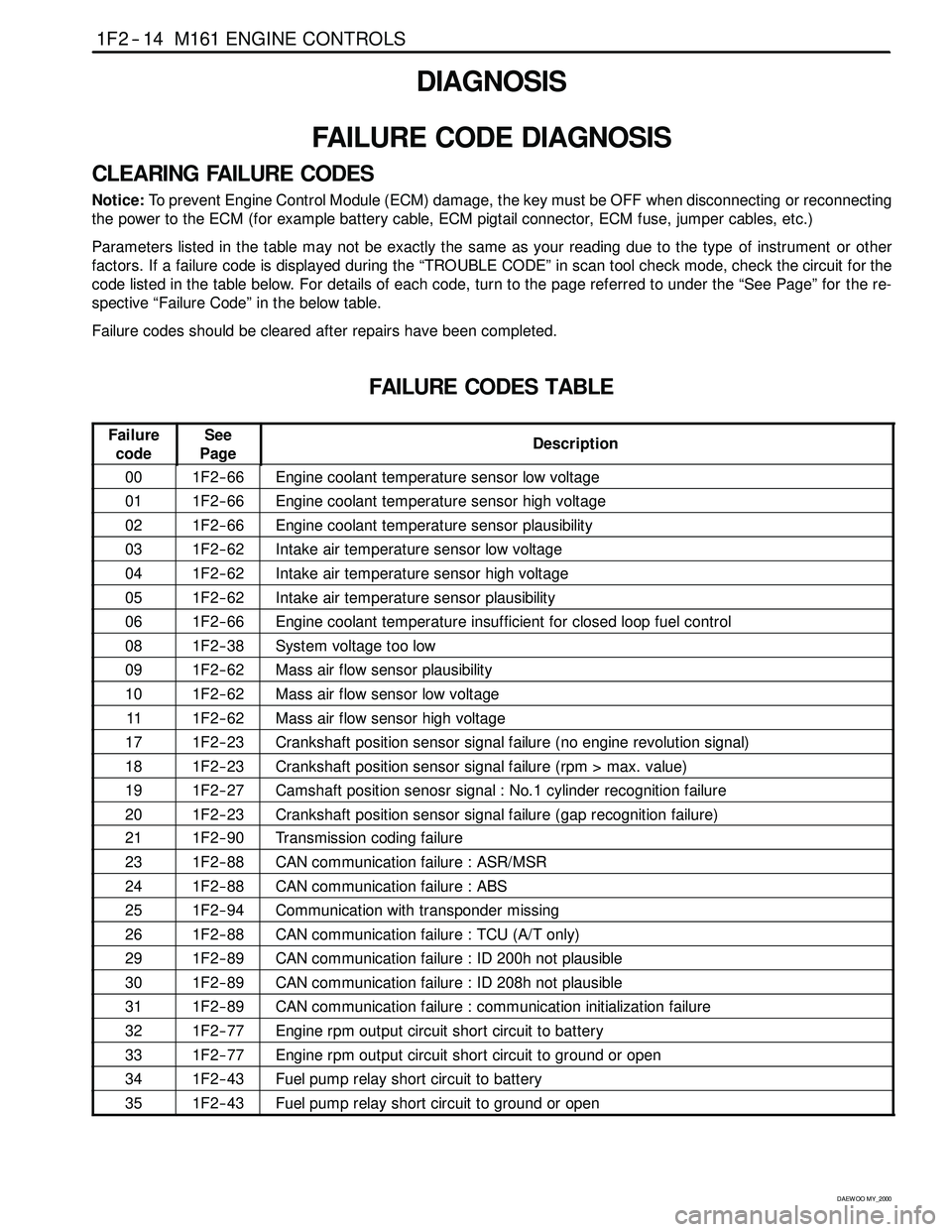
DIAGNOSIS
FAILURE CODE DIAGNOSIS
CLEARING FAILURE CODES
Notice:To prevent Engine Control Module (ECM) damage, the key must be OFF when disconnecting or reconnecting
the power to the ECM (for example battery cable, ECM pigtail connector, ECM fuse, jumper cables, etc.)
Parameters listed in the table may not be exactly the same as your reading due to the type of instrument or other
factors. If a failure code is displayed during the “TROUBLE CODE” in scan tool check mode, check the circuit for the
code listed in the table below. For details of each code, turn to the page referred to under the “See Page” for the re-
spective “Failure Code” in the below table.
Failure codes should be cleared after repairs have been completed.
FAILURE CODES TABLE
Failure
codeSee
PageDescription
001F2 -- 66Engine coolant temperature sensor low voltage
011F2 -- 66Engine coolant temperature sensor high voltage
021F2 -- 66Engine coolant temperature sensor plausibility
031F2 -- 62Intake air temperature sensor low voltage
041F2 -- 62Intake air temperature sensor high voltage
051F2 -- 62Intake air temperature sensor plausibility
061F2 -- 66Engine coolant temperature insufficient for closed loop fuel control
081F2 -- 38System voltage too low
091F2 -- 62Mass air flow sensor plausibility
101F2 -- 62Mass air flow sensor low voltage
111F2 -- 62Mass air flow sensor high voltage
171F2 -- 23Crankshaft position sensor signal failure (no engine revolution signal)
181F2 -- 23Crankshaft position sensor signal failure (rpm > max. value)
191F2 -- 27Camshaft position senosr signal : No.1 cylinder recognition failure
201F2 -- 23Crankshaft position sensor signal failure (gap recognition failure)
211F2 -- 90Transmission coding failure
231F2 -- 88CAN communication failure : ASR/MSR
241F2 -- 88CAN communication failure : ABS
251F2 -- 94Communication with transponder missing
261F2 -- 88CAN communication failure : TCU (A/T only)
291F2 -- 89CAN communication failure : ID 200h not plausible
301F2 -- 89CAN communication failure : ID 208h not plausible
311F2 -- 89CAN communication failure : communication initialization failure
321F2 -- 77Engine rpm output circuit short circuit to battery
331F2 -- 77Engine rpm output circuit short circuit to ground or open
341F2 -- 43Fuel pump relay short circuit to battery
351F2 -- 43Fuel pump relay short circuit to ground or open
Page 507 of 2053

M161 ENGINE CONTROLS 1F2 -- 89
D AEW OO M Y_2000
Failure
CodeDescriptionTrouble AreaMaintenance Hint
29
CAN communication
failure: ID 200h not
plausibleWhen CAN signal message
missing or implausibility for
ABS/ABD unit or not
initialized conditionDInspection the ABS/ABD unit with
CAN connection
DInspection the ECM pin 38, 37 about
short circuit or open with bad contact
DInspection the ECM
30
CAN communication
failure: ID 208h not
plausibleWhen CAN signal message
missing or implausibility for
ABS/ABD unit or not
initialized conditionDInspection the ABS/ABD unit with
CAN connection
DInspection the ECM pin 38, 37 about
short circuit or open with bad contact
DInspection the ECM
31
CAN communication
failure: communication
initialization failure
When CAN signal message
missing or implausibility for
each unit (ABS, ASR, TCM,
TOD etc.) or not initialized
conditionDInspection the each control unit with
CAN connection
DInspection the ECM pin 38, 37 about
short circuit or open with bad contact
DInspection the ECM
59
CAN communication
failure: MSR data
transmission not
plausibleWhen CAN signal message
missing or implausibility for
MSR unit or not initialized
condition
DInspection the MSR unit with CAN
connection
DInspection the Engine Control Module
(ECM) pin 38, 37 about short circuit or
open with bad contact
DInspection the ECM
60
CAN communication
failure: ASR data
transmission not
plausibleWhen CAN signal message
missing or implausibility for
ASR unit or not initialized
condition
DInspection the ASR unit with CAN
connection
DInspection the Engine Control Module
(ECM) pin 38, 37 about short circuit or
open with bad contact
DInspection the ECM
Circuit Description
The provision for communicating with the ECM is the Data Link Connector (DLC). It is located in the instrument panel
fuse block. The DLC is used to connect the scan tool. Battery power and ground is supplied for the scan tool through
the DLC. CAN line is used to communicate with the other module such as the Transmission Control Module (TCM) and
Transfer Case Control Unit (TCCU).
Keyword 2000 Serial Data Communications
Each bit of information can have one of two lengths: long or short. This allows vehicle wiring to be reduced by transmit-
ting and receiving multiple signals over a singles wire. The message carried on KWP 2000 data streams are also priori-
tized. If two messages attempt to establish communications on the data line at the same time, only the message with
higher prioritywill must wait.
Page 1382 of 2053
SSANGYONG MY2002
5D1-12 TRANSFER CASE
Both Speed Sensor Faulty
If both the front and rear speed sensors are faulty con
tinuously for 0.5 seconds the 4WD CHECK lamp is
illuminated. The TCCU then responds as follows:
1. If the system is in high range the TCCU sets the
EMC touch off level based on a vehicle speed of
0 and wheel slip control is suspended.
2. If the system is in low range, the EMC duty cycle
is set to maximum until the system is shifted out
of low range.
3. All electric shift activity is halted until the Ignition
is cycled. If a shift is in progress it will be
completed.
If both speed sensors recover continuously for 0.5 sec-
ond the TCCU will function normally. The 4WD CHECK
lamp is turned off but the fault code will remain in
memory.
Electro-Magnetic Clutch Test
The electromagnetic clutch (EMC) is tested for open
circuit or short circuit to ground. If a fault is detected
continuously for 0.8 second the 4WD CHECK lamp is
turned on and all TODTM activity is halted.
If the EMC recovers continuously for 0.8 second the
TCCU will function normally. The 4WD CHECK lamp is
turned off but the fault code will remain in memory.
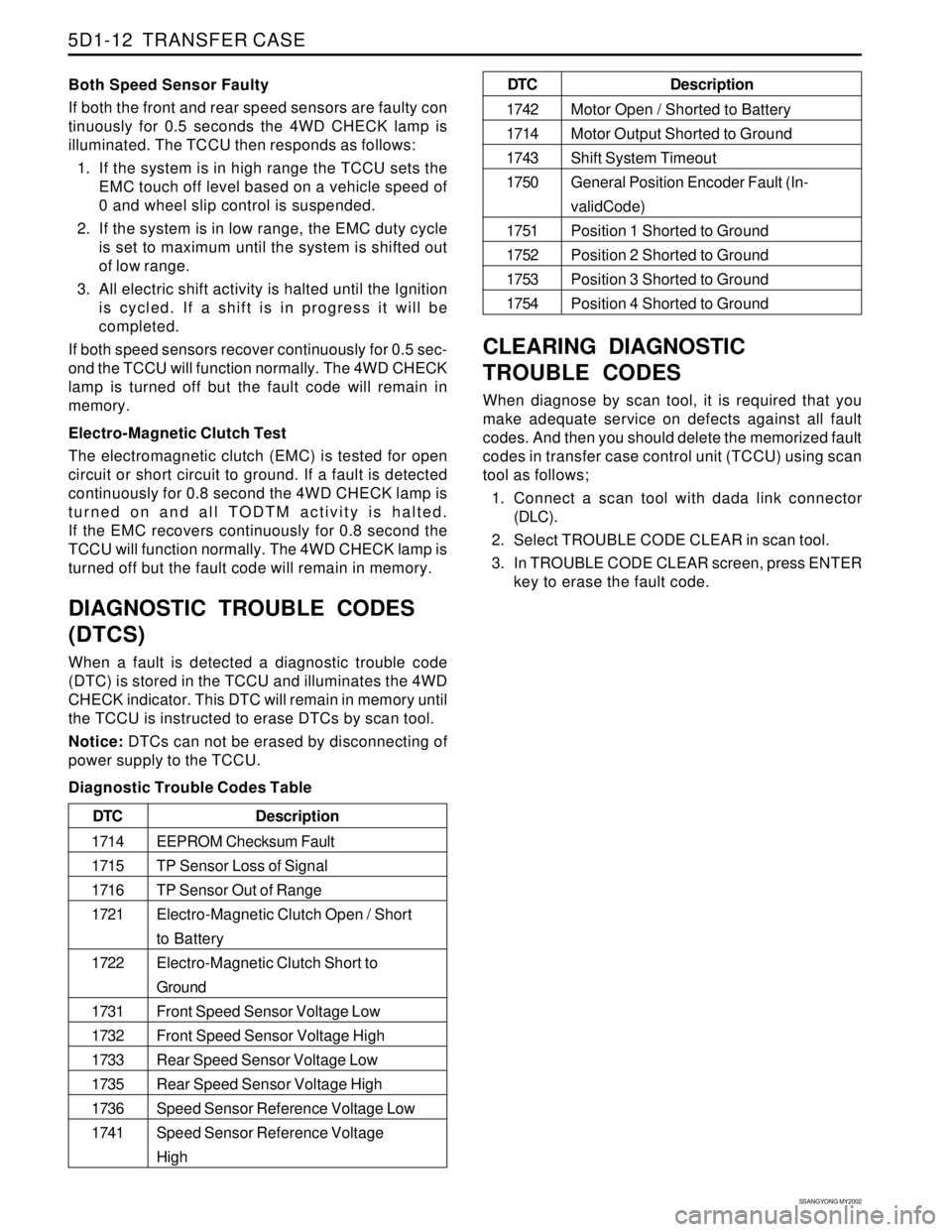
DIAGNOSTIC TROUBLE CODES
(DTCS)
When a fault is detected a diagnostic trouble code
(DTC) is stored in the TCCU and illuminates the 4WD
CHECK indicator. This DTC will remain in memory until
the TCCU is instructed to erase DTCs by scan tool.
Notice: DTCs can not be erased by disconnecting of
power supply to the TCCU.
Diagnostic Trouble Codes Table
CLEARING DIAGNOSTIC
TROUBLE CODES
When diagnose by scan tool, it is required that you
make adequate service on defects against all fault
codes. And then you should delete the memorized fault
codes in transfer case control unit (TCCU) using scan
tool as follows;
1. Connect a scan tool with dada link connector
(DLC).
2. Select TROUBLE CODE CLEAR in scan tool.
3. In TROUBLE CODE CLEAR screen, press ENTER
key to erase the fault code.
Description
EEPROM Checksum Fault
TP Sensor Loss of Signal
TP Sensor Out of Range
Electro-Magnetic Clutch Open / Short
to Battery
Electro-Magnetic Clutch Short to
Ground
Front Speed Sensor Voltage Low
Front Speed Sensor Voltage High
Rear Speed Sensor Voltage Low
Rear Speed Sensor Voltage High
Speed Sensor Reference Voltage Low
Speed Sensor Reference Voltage
High DTC
1714
1715
1716
1721
1722
1731
1732
1733
1735
1736
1741
Description
Motor Open / Shorted to Battery
Motor Output Shorted to Ground
Shift System Timeout
General Position Encoder Fault (In-
validCode)
Position 1 Shorted to Ground
Position 2 Shorted to Ground
Position 3 Shorted to Ground
Position 4 Shorted to Ground DTC
1742
1714
1743
1750
1751
1752
1753
1754
Page 1488 of 2053
SSANGYONG MY2002
6E-2 POWER STEERING AND COLUMN
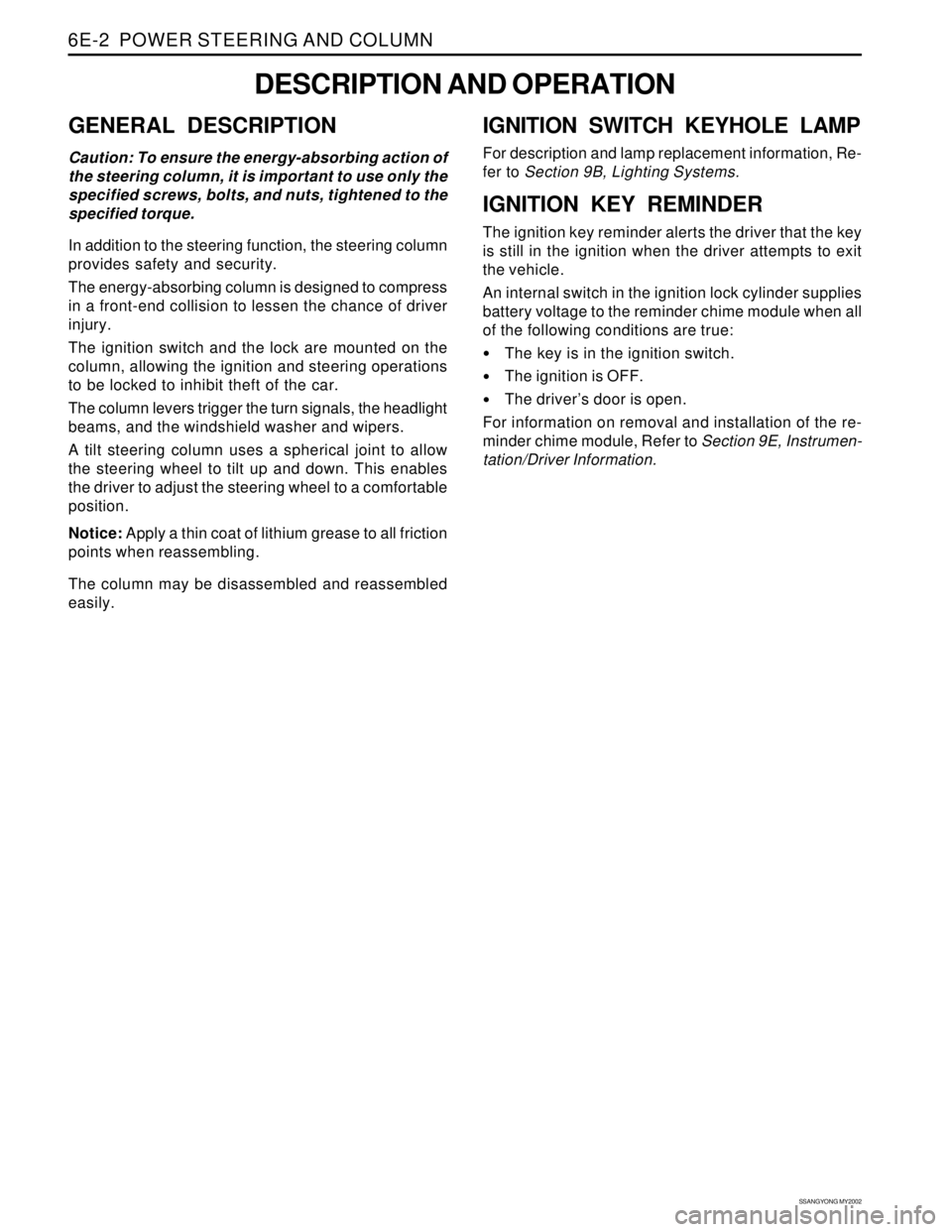
GENERAL DESCRIPTION
Caution: To ensure the energy-absorbing action of
the steering column, it is important to use only the
specified screws, bolts, and nuts, tightened to the
specified torque.
In addition to the steering function, the steering column
provides safety and security.
The energy-absorbing column is designed to compress
in a front-end collision to lessen the chance of driver
injury.
The ignition switch and the lock are mounted on the
column, allowing the ignition and steering operations
to be locked to inhibit theft of the car.
The column levers trigger the turn signals, the headlight
beams, and the windshield washer and wipers.
A tilt steering column uses a spherical joint to allow
the steering wheel to tilt up and down. This enables
the driver to adjust the steering wheel to a comfortable
position.
Notice: Apply a thin coat of lithium grease to all friction
points when reassembling.
The column may be disassembled and reassembled
easily.
DESCRIPTION AND OPERATION
IGNITION SWITCH KEYHOLE LAMP
For description and lamp replacement information, Re-
fer to Section 9B, Lighting Systems.
IGNITION KEY REMINDER
The ignition key reminder alerts the driver that the key
is still in the ignition when the driver attempts to exit
the vehicle.
An internal switch in the ignition lock cylinder supplies
battery voltage to the reminder chime module when all
of the following conditions are true:
•The key is in the ignition switch.
The ignition is OFF.
The driver’s door is open.
For information on removal and installation of the re-
minder chime module, Refer to Section 9E, Instrumen-
tation/Driver Information.
Page 1497 of 2053
POWER STEERING AND COLUMN 6E-11
SSANGYONG MY2002
KAA6E040
KAA6E100
KAA6E090
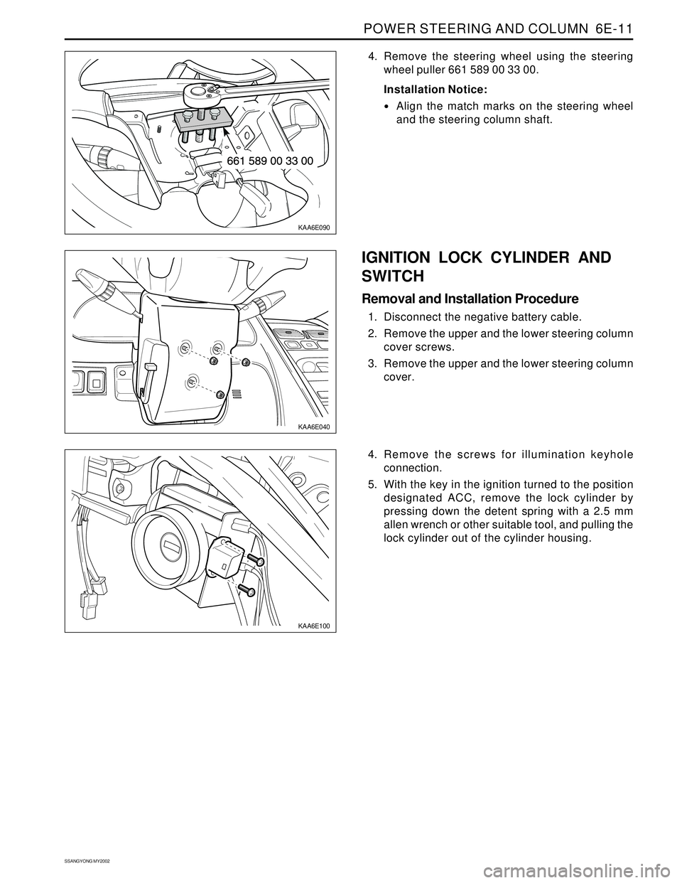
4. Remove the steering wheel using the steering
wheel puller 661 589 00 33 00.
Installation Notice:
Align the match marks on the steering wheel
and the steering column shaft.
IGNITION LOCK CYLINDER AND
SWITCH
Removal and Installation Procedure
1. Disconnect the negative battery cable.
2. Remove the upper and the lower steering column
cover screws.
3. Remove the upper and the lower steering column
cover.
4. Remove the screws for illumination keyhole
connection.
5. With the key in the ignition turned to the position
designated ACC, remove the lock cylinder by
pressing down the detent spring with a 2.5 mm
allen wrench or other suitable tool, and pulling the
lock cylinder out of the cylinder housing.
Page 1688 of 2053
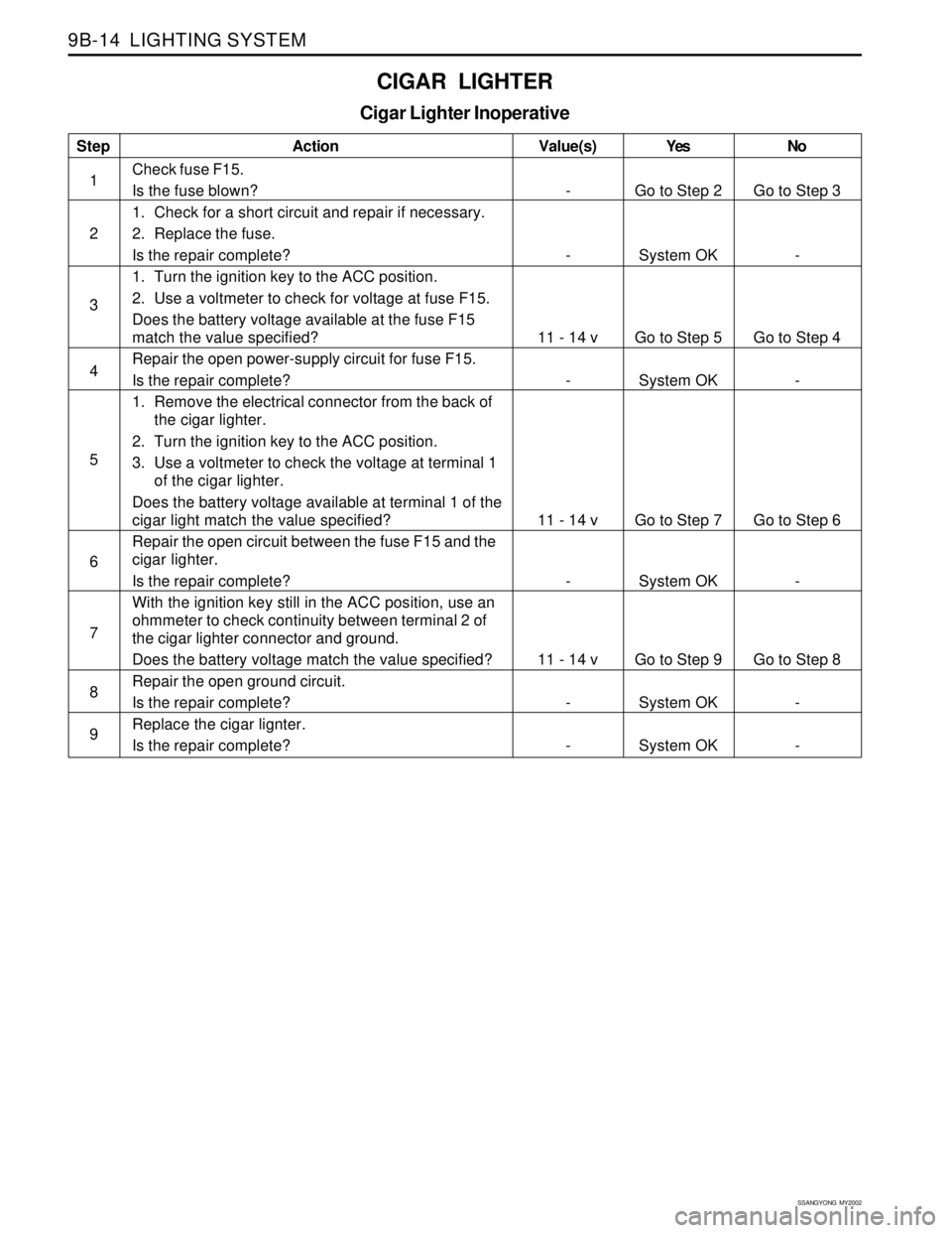
SSANGYONG MY2002
9B-14 LIGHTING SYSTEM
CIGAR LIGHTER
Cigar Lighter Inoperative
Step
1
2
3
4
5
6
7
8
9Action
Check fuse F15.
Is the fuse blown?
1. Check for a short circuit and repair if necessary.
2. Replace the fuse.
Is the repair complete?
1. Turn the ignition key to the ACC position.
2. Use a voltmeter to check for voltage at fuse F15.
Does the battery voltage available at the fuse F15
match the value specified?
Repair the open power-supply circuit for fuse F15.
Is the repair complete?
1. Remove the electrical connector from the back of
the cigar lighter.
2. Turn the ignition key to the ACC position.
3. Use a voltmeter to check the voltage at terminal 1
of the cigar lighter.
Does the battery voltage available at terminal 1 of the
cigar light match the value specified?
Repair the open circuit between the fuse F15 and the
cigar lighter.
Is the repair complete?
With the ignition key still in the ACC position, use an
ohmmeter to check continuity between terminal 2 of
the cigar lighter connector and ground.
Does the battery voltage match the value specified?
Repair the open ground circuit.
Is the repair complete?
Replace the cigar lignter.
Is the repair complete?Yes
Go to Step 2
System OK
Go to Step 5
System OK
Go to Step 7
System OK
Go to Step 9
System OK
System OKNo
Go to Step 3
-
Go to Step 4
-
Go to Step 6
-
Go to Step 8
-
- Value(s)
-
-
11 - 14 v
-
11 - 14 v
-
11 - 14 v
-
-