1997 SSANGYONG KORANDO battery replacement
[x] Cancel search: battery replacementPage 551 of 2053
D AEW OO M Y_2000
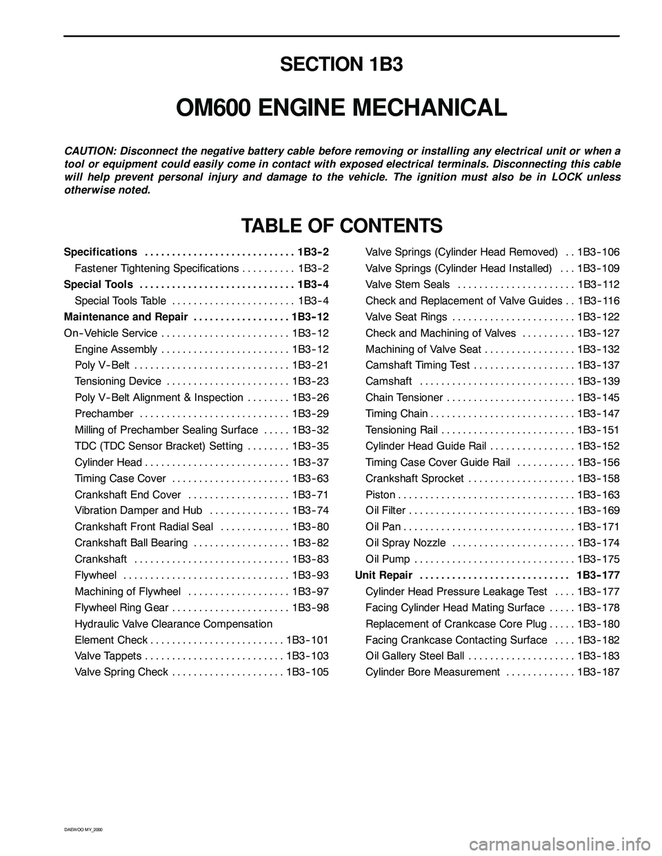
SECTION 1B3
OM600 ENGINE MECHANICAL
CAUTION: Disconnect the negative battery cable before removing or installing any electrical unit or when a
tool or equipment could easily come in contact with exposed electrical terminals. Disconnecting this cable
will help prevent personal injury and damage to the vehicle. The ignition must also be in LOCK unless
otherwise noted.
TABLE OF CONTENTS
Specifications 1B3 -- 2............................
Fastener Tightening Specifications 1B3 -- 2..........
Special Tools 1B3 -- 4.............................
Special Tools Table 1B3-- 4.......................
Maintenance and Repair 1B3 -- 12..................
On-- Vehicle Service 1B3-- 12........................
Engine Assembly 1B3-- 12........................
Poly V-- Belt 1B3 -- 21.............................
Tensioning Device 1B3-- 23.......................
Poly V-- Belt Alignment & Inspection 1B3-- 26........
Prechamber 1B3-- 29............................
Milling of Prechamber Sealing Surface 1B3 -- 32.....
TDC (TDC Sensor Bracket) Setting 1B3 -- 35........
Cylinder Head 1B3-- 37...........................
Timing Case Cover 1B3 -- 63......................
Crankshaft End Cover 1B3-- 71...................
Vibration Damper and Hub 1B3-- 74...............
Crankshaft Front Radial Seal 1B3-- 80.............
Crankshaft Ball Bearing 1B3-- 82..................
Crankshaft 1B3-- 83.............................
Flywheel 1B3 -- 93...............................
Machining of Flywheel 1B3-- 97...................
Flywheel Ring Gear 1B3 -- 98......................
Hydraulic Valve Clearance Compensation
Element Check 1B3-- 101.........................
Valve Tappets 1B3-- 103..........................
Valve Spring Check 1B3-- 105.....................Valve Springs (Cylinder Head Removed) 1B3-- 106..
Valve Springs (Cylinder Head Installed) 1B3-- 109...
Valve Stem Seals 1B3-- 112......................
Check and Replacement of Valve Guides 1B3-- 116..
Valve Seat Rings 1B3-- 122.......................
Check and Machining of Valves 1B3-- 127..........
Machining of Valve Seat 1B3-- 132.................
Camshaft Timing Test 1B3-- 137...................
Camshaft 1B3-- 139.............................
Chain Tensioner 1B3-- 145........................
Timing Chain 1B3-- 147...........................
Tensioning Rail 1B3-- 151.........................
Cylinder Head Guide Rail 1B3-- 152................
Timing Case Cover Guide Rail 1B3-- 156...........
Crankshaft Sprocket 1B3-- 158....................
Piston 1B3-- 163.................................
Oil Filter 1B3-- 169...............................
Oil Pan 1B3-- 171................................
Oil Spray Nozzle 1B3-- 174.......................
Oil Pump 1B3-- 175..............................
Unit Repair 1B3 -- 177............................
Cylinder Head Pressure Leakage Test 1B3-- 177....
Facing Cylinder Head Mating Surface 1B3 -- 178.....
Replacement of Crankcase Core Plug 1B3-- 180.....
Facing Crankcase Contacting Surface 1B3 -- 182....
Oil Gallery Steel Ball 1B3-- 183....................
Cylinder Bore Measurement 1B3-- 187.............
Page 763 of 2053

D AEW OO M Y_2000
SECTION 1F3
OM600 ENGINE CONTROLS
Caution: Disconnect the negative battery cable before removing or installing any electrical unit or when a
tool or equipment could easily come in contact with exposed electrical terminals. Disconnecting this cable
will help prevent personal injury and damage to the vehicle. The ignition must also be in LOCK unless other -
wise noted.
TABLE OF CONTENTS
Specifications 1F3 -- 1............................
Fastener Tightening Specifications 1F3 -- 1..........
Maintenance and Repair 1F3 -- 2...................
On -- Vehicle Service 1F3 -- 2.........................
Fuel System 1F3 -- 2.............................
Fuel Injection Pump Coding 1F3 -- 3................
Fuel Tank 1F3 -- 4...............................
Vacuum Control System Test 1F3 -- 5..............
Vacuum Pump Test 1F3 -- 10......................
Vacuum Pump 1F3 -- 12..........................
Vacuum Unit Replacement 1F3 -- 14...............
Idle Speed Adjustment 1F3 -- 15...................Fuel Pump Test 1F3 -- 17.........................
Fuel Pump 1F3 -- 20.............................
Injection Nozzle Test 1F3-- 21.....................
Injection Nozzles 1F3-- 24........................
Injection Nozzle Repair 1F3 -- 26...................
Removal and Installation of
Injection Timing Device 1F3 -- 29.................
Injection Timing Device 1F3 -- 34...................
StartofDeliveryTest
(Position Sensor, RIV Method) 1F3 -- 36..........
Fuel Injection Pump 1F3 -- 45.....................
SPECIFICATIONS
FASTENER TIGHTENING SPECIFICATIONS
ApplicationN∙mLb-- FtLb-In
Fuel Tank Mounting Nut28 -- 4721 -- 35--
Fuel Pump Pressure Line1310--
Fuel Injection Nozzle35 -- 4026 -- 30--
Fuel Injection Pipe1813--
Nozzle Tensioning Nut8059--
Screw Plug3022--
Left -- Hand Thread Bolt4634--
Page 1013 of 2053
SSANGYONG MY2002
4F-30 ABS AND TCS
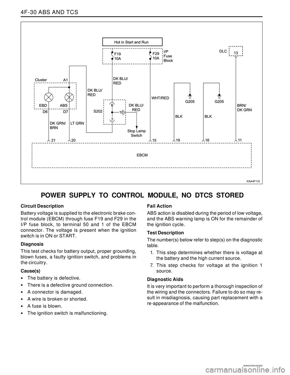
POWER SUPPLY TO CONTROL MODULE, NO DTCS STORED
KAA4F110
Circuit Description
Battery voltage is supplied to the electronic brake con-
trol module (EBCM) through fuse F19 and F29 in the
I/P fuse block, to terminal 50 and 1 of the EBCM
connector. The voltage is present when the ignition
switch is in ON or START.
Diagnosis
This test checks for battery output, proper grounding,
blown fuses, a faulty ignition switch, and problems in
the circuitry.
Cause(s)
The battery is defective.
There is a defective ground connection.
A connector is damaged.
A wire is broken or shorted.
A fuse is blown.
The ignition switch is malfunctioning.Fail Action
ABS action is disabled during the period of low voltage,
and the ABS warning lamp is ON for the remainder of
the ignition cycle.
Test Description
The number(s) below refer to step(s) on the diagnostic
table.
1. This step determines whether there is voltage at
the battery and the high current source.
7. This step checks for voltage at the ignition 1
source.
Diagnostic Aids
It is very important to perform a thorough inspection of
the wiring and the connectors. Failure to do so may re-
sult in misdiagnosis, causing part replacement with a
re-appearance of the malfunction.
Page 1059 of 2053
SSANGYONG MY2002
4F-76 ABS AND TCS
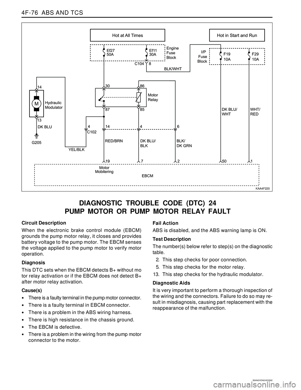
DIAGNOSTIC TROUBLE CODE (DTC) 24
PUMP MOTOR OR PUMP MOTOR RELAY FAULT
KAA4F220
Circuit Description
When the electronic brake control module (EBCM)
grounds the pump motor relay, it closes and provides
battery voltage to the pump motor. The EBCM senses
the voltage applied to the pump motor to verify motor
operation.
Diagnosis
This DTC sets when the EBCM detects B+ without mo
tor relay activation or if the EBCM does not detect B+
after motor relay activation.
Cause(s)
There is a faulty terminal in the pump motor connector.
There is a faulty terminal in EBCM connector.
There is a problem in the ABS wiring harness.
There is high resistance in the chassis ground.
The EBCM is defective.
There is a problem in the wiring from the pump motor
connector to the motor.Fail Action
ABS is disabled, and the ABS warning lamp is ON.
Test Description
The number(s) below refer to step(s) on the diagnostic
table.
2. This step checks for poor connection.
5. This step checks for the motor relay.
13. This step checks for the hydraulic modulator.
Diagnostic Aids
It is very important to perform a thorough inspection of
the wiring and the connectors. Failure to do so may re-
sult in misdiagnosis, causing part replacement with the
reappearance of the malfunction.
Page 1063 of 2053
SSANGYONG MY2002
4F-80 ABS AND TCS
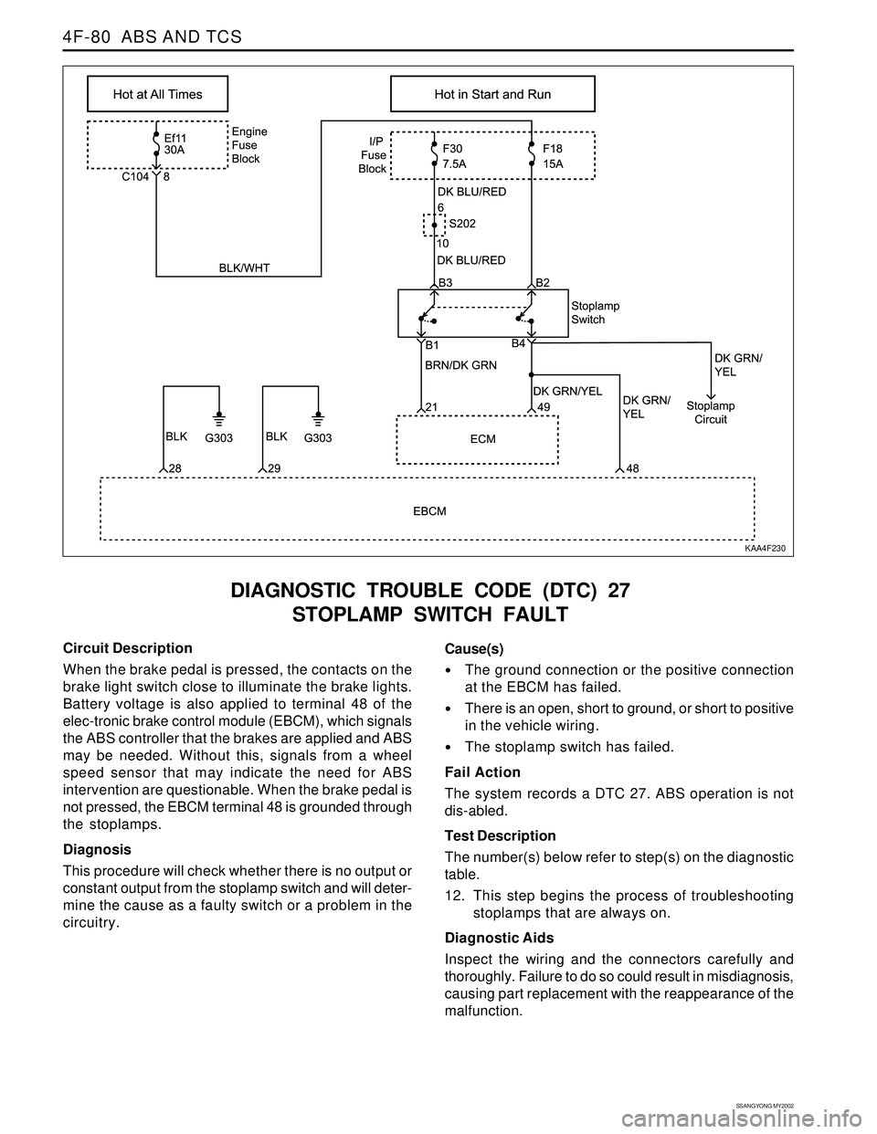
DIAGNOSTIC TROUBLE CODE (DTC) 27
STOPLAMP SWITCH FAULT
KAA4F230
Circuit Description
When the brake pedal is pressed, the contacts on the
brake light switch close to illuminate the brake lights.
Battery voltage is also applied to terminal 48 of the
elec-tronic brake control module (EBCM), which signals
the ABS controller that the brakes are applied and ABS
may be needed. Without this, signals from a wheel
speed sensor that may indicate the need for ABS
intervention are questionable. When the brake pedal is
not pressed, the EBCM terminal 48 is grounded through
the stoplamps.
Diagnosis
This procedure will check whether there is no output or
constant output from the stoplamp switch and will deter-
mine the cause as a faulty switch or a problem in the
circuitry.Cause(s)
The ground connection or the positive connection
at the EBCM has failed.
There is an open, short to ground, or short to positive
in the vehicle wiring.
The stoplamp switch has failed.
Fail Action
The system records a DTC 27. ABS operation is not
dis-abled.
Test Description
The number(s) below refer to step(s) on the diagnostic
table.
12. This step begins the process of troubleshooting
stoplamps that are always on.
Diagnostic Aids
Inspect the wiring and the connectors carefully and
thoroughly. Failure to do so could result in misdiagnosis,
causing part replacement with the reappearance of the
malfunction.
Page 1067 of 2053
SSANGYONG MY2002
4F-84 ABS AND TCS
DIAGNOSTIC TROUBLE CODE (DTC) 28
LOW VOLTAGE FAULT
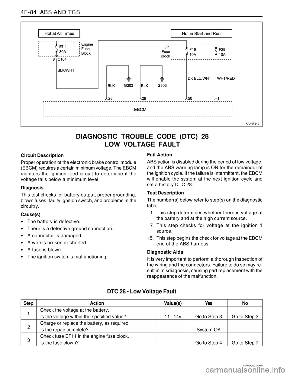
KAA4F240
Circuit Description
Proper operation of the electronic brake control module
(EBCM) requires a certain minimum voltage. The EBCM
monitors the ignition feed circuit to determine if the
voltage falls below a minimum level.
Diagnosis
This test checks for battery output, proper grounding,
blown fuses, faulty ignition switch, and problems in the
circuitry.
Cause(s)
The battery is defective.
There is a defective ground connection.
A connector is damaged.
A wire is broken or shorted.
A fuse is blown.
The ignition switch is malfunctioning.Fail Action
ABS action is disabled during the period of low voltage,
and the ABS warning lamp is ON for the remainder of
the ignition cycle. If the failure is intermittent, the EBCM
will enable the system at the next ignition cycle and
set a history DTC 28.
Test Description
The number(s) below refer to step(s) on the diagnostic
table.
1. This step determines whether there is voltage at
the battery and at the high current source.
7. This step checks for voltage at the ignition 1
source.
15. This step begins the check for voltage at the EBCM
end of the ABS harness.
Diagnostic Aids
It is very important to perform a thorough inspection of
the wiring and the connectors. Failure to do so may re-
sult in misdiagnosis, causing part replacement with the
reappearance of the malfunction.
Step
1
2
3
Action
Go to Step 3
System OK
Go to Step 4Go to Step 2
-
Go to Step 7 11 - 14v
-
-
Check the voltage at the battery.
Is the voltage within the specified value?
Charge or replace the battery, as required.
Is the repair complete?
Check fuse EF11 in the engine fuse block.
Is the fuse blown?
DTC 28 - Low Voltage Fault
Value(s) Yes No
Page 1082 of 2053
ABS AND TCS 4F-99
SSANGYONG MY2002
REPAIR INSTRUCTIONS
ON-VEHICLE SERVICE
SERVICE PRECAUTIONS
Caution: Brake Fluid may irritate eyes and skin. In
case of contact, take the following actions:
Eye contact - rinse thoroughly with water.
Skin contact - wash with soap and water.
Ingestion - consult a physician immediately.
Caution: To help avoid personal injury due to poor
braking. DO NOT Tap into the vehicle’s brake system
to operate a trailer brake system.
Notice: When fasteners are removed, always reinstall
them at the same location from which they were
removed. If a fastener needs to be replaced, use the
correct part number fastener for is not available, a
fastener of equal size and strength (or stronger) may
be used. Fasteners that are not reused, and those
requiring thread-locking compound will be called out.
The correct torque values must be used when installing
fasteners that require them. If the above procedures
are not followed, parts or system damage could result.
Notice: Use only DOT-3 equivalent hydraulic brake
fluid. The use of DOT-5 (silicone) brake fluid is not
recommended. Reduced brake performance or
durability may result.
Notice: Avoid spilling brake fluid on any the vehicle’s
painted surfaces, wiring, cables or electrical
connectors. Brake fluid will damage paint and electrical
connections. If any fluid is spilled on the vehicle, flush
the area with water to lessen the damage.
Electronic System Service Precautions
Take care to avoid electronic brake control module
(EBCM) circuit overloading. In testing for opens or
shorts, do not ground or apply voltage to any circuit
unless instructed to do so by the diagnostic procedure.
Test circuits only with a high-impedance multi-meter.
Never remove or apply power to any control module
with the ignition switch in the ON position. Always turn
the ignition to the OFF position before removing or
connecting battery cables, fuses or connectors.
General Service Precautions
Disconnect the EBCM connector before performing any
vehicle welding work using an electric arc welder.
Do not attempt to disassemble any component
designated as nonserviceable. The hydraulic modulator
and the EBCM can be separated from each other and
replaced separately but cannot be serviced. They have
no replaceable parts, and there is no replaceable parts,
and there is no access to the components they contain.
Bleeding System
Replacement modulators are shipped already filled
and bled. In normal procedures requiring removal of
the modulator, such as to replace the EBCM, air will
not enter the modulator, and normal bleeding will be
all that is needed.
If air enters the hydraulic modulator, or if an unfilled
modulator is installed, use the brake bleeding program
in the scan tool to bleed the modulator. Manual
bleeding of the hydraulic modulator is not possible.
Page 1085 of 2053
SSANGYONG MY2002
4F-102 ABS AND TCS
ACCELERATION SENSOR
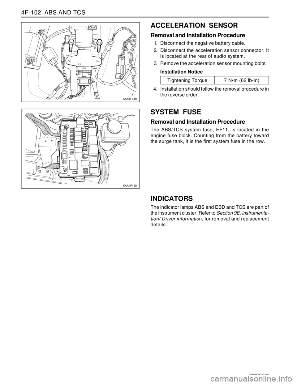
Removal and Installation Procedure
1. Disconnect the negative battery cable.
2. Disconnect the acceleration sensor connector. It
is located at the rear of audio system.
3. Remove the acceleration sensor mounting bolts.
Installation Notice
SYSTEM FUSE
Removal and Installation Procedure
The ABS/TCS system fuse, EF11, is located in the
engine fuse block. Counting from the battery toward
the surge tank, it is the first system fuse in the row.
KAA4F410
KAA4F420
Tightening Torque 7 Nm (62 lb-in)
4. Installation should follow the removal procedure in
the reverse order.
INDICATORS
The indicator lamps ABS and EBD and TCS are part of
the instrument cluster. Refer to Section 9E, instrumenta-
tion/ Driver information, for removal and replacement
details.