1997 SSANGYONG KORANDO battery replacement
[x] Cancel search: battery replacementPage 1372 of 2053
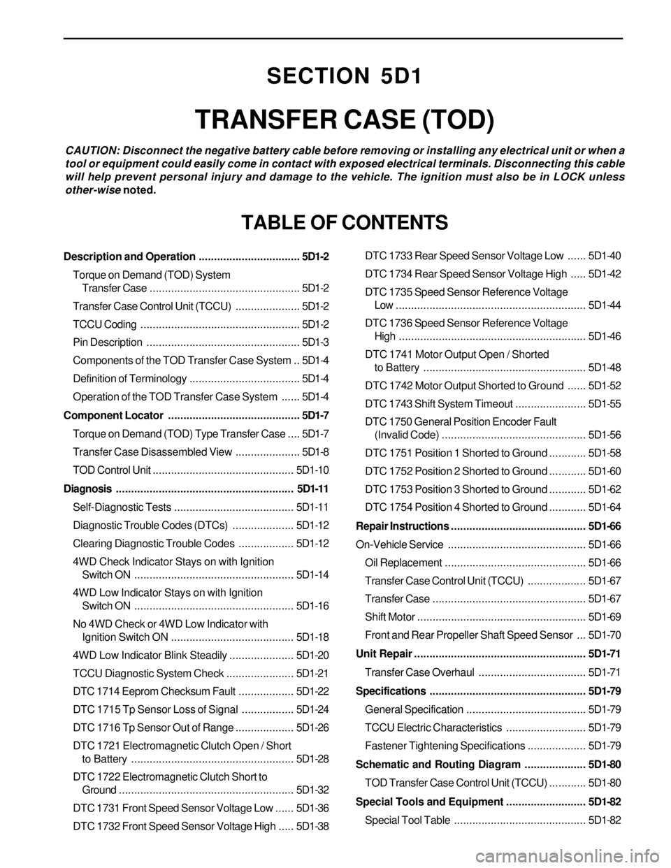
SECTION 5D1
TRANSFER CASE (TOD)
CAUTION: Disconnect the negative battery cable before removing or installing any electrical unit or when a
tool or equipment could easily come in contact with exposed electrical terminals. Disconnecting this cable
will help prevent personal injury and damage to the vehicle. The ignition must also be in LOCK unless
other-wise noted.
TABLE OF CONTENTS
Description and Operation.................................5D1-2
Torque on Demand (TOD) System
Transfer Case.................................................5D1-2
Transfer Case Control Unit (TCCU).....................5D1-2
TCCU Coding....................................................5D1-2
Pin Description..................................................5D1-3
Components of the TOD Transfer Case System ..5D1-4
Definition of Terminology....................................5D1-4
Operation of the TOD Transfer Case System......5D1-4
Component Locator...........................................5D1-7
Torque on Demand (TOD) Type Transfer Case....5D1-7
Transfer Case Disassembled View.....................5D1-8
TOD Control Unit..............................................5D1-10
Diagnosis..........................................................5D1-11
Self-Diagnostic Tests.......................................5D1-11
Diagnostic Trouble Codes (DTCs)....................5D1-12
Clearing Diagnostic Trouble Codes..................5D1-12
4WD Check Indicator Stays on with Ignition
Switch ON....................................................5D1-14
4WD Low Indicator Stays on with Ignition
Switch ON....................................................5D1-16
No 4WD Check or 4WD Low Indicator with
Ignition Switch ON........................................5D1-18
4WD Low Indicator Blink Steadily.....................5D1-20
TCCU Diagnostic System Check......................5D1-21
DTC 1714 Eeprom Checksum Fault..................5D1-22
DTC 1715 Tp Sensor Loss of Signal.................5D1-24
DTC 1716 Tp Sensor Out of Range...................5D1-26
DTC 1721 Electromagnetic Clutch Open / Short
to Battery.....................................................5D1-28
DTC 1722 Electromagnetic Clutch Short to
Ground.........................................................5D1-32
DTC 1731 Front Speed Sensor Voltage Low......5D1-36
DTC 1732 Front Speed Sensor Voltage High.....5D1-38DTC 1733 Rear Speed Sensor Voltage Low......5D1-40
DTC 1734 Rear Speed Sensor Voltage High.....5D1-42
DTC 1735 Speed Sensor Reference Voltage
Low ..............................................................5D1-44
DTC 1736 Speed Sensor Reference Voltage
High.............................................................5D1-46
DTC 1741 Motor Output Open / Shorted
to Battery.....................................................5D1-48
DTC 1742 Motor Output Shorted to Ground......5D1-52
DTC 1743 Shift System Timeout.......................5D1-55
DTC 1750 General Position Encoder Fault
(Invalid Code)...............................................5D1-56
DTC 1751 Position 1 Shorted to Ground............5D1-58
DTC 1752 Position 2 Shorted to Ground............5D1-60
DTC 1753 Position 3 Shorted to Ground............5D1-62
DTC 1754 Position 4 Shorted to Ground............5D1-64
Repair Instructions............................................5D1-66
On-Vehicle Service.............................................5D1-66
Oil Replacement..............................................5D1-66
Transfer Case Control Unit (TCCU)...................5D1-67
Transfer Case..................................................5D1-67
Shift Motor.......................................................5D1-69
Front and Rear Propeller Shaft Speed Sensor ...5D1-70
Unit Repair........................................................5D1-71
Transfer Case Overhaul...................................5D1-71
Specifications...................................................5D1-79
General Specification.......................................5D1-79
TCCU Electric Characteristics..........................5D1-79
Fastener Tightening Specifications...................5D1-79
Schematic and Routing Diagram....................5D1-80
TOD Transfer Case Control Unit (TCCU)............5D1-80
Special Tools and Equipment..........................5D1-82
Special Tool Table ...........................................5D1-82
Page 1389 of 2053
TRANSFER CASE 5D1-67
SSANGYONG MY2002
KAA5D260
KAA5D270
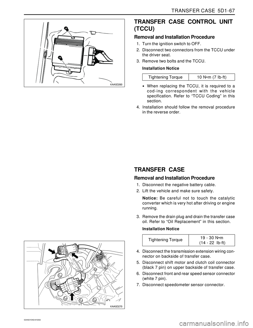
TRANSFER CASE CONTROL UNIT
(TCCU)
Removal and Installation Procedure
1. Turn the ignition switch to OFF.
2. Disconnect two connectors from the TCCU under
the driver seat.
3. Remove two bolts and the TCCU.
Installation Notice
Tightening Torque 10 Nm (7 lb-ft)
When replacing the TCCU, it is required to a
cod-ing correspondent with the vehicle
specification. Refer to “TCCU Coding” in this
section.
4. Installation should follow the removal procedure
in the reverse order.
TRANSFER CASE
Removal and Installation Procedure
1. Disconnect the negative battery cable.
2. Lift the vehicle and make sure safety.
Notice: Be careful not to touch the catalytic
converter which is very hot after driving or engine
running.
3. Remove the drain plug and drain the transfer case
oil. Refer to “Oil Replacement” in this section.
Installation Notice
4. Disconnect the transmission extension wiring con-
nector on backside of transfer case.
5. Disconnect shift motor and clutch coil connector
(black 7 pin) on upper backside of transfer case.
6. Disconnect front and rear speed sensor connector
(white 7 pin).
7. Disconnect speedometer sensor connector.
Tightening Torque19 - 30 Nm
(14 - 22 lb-ft)
Page 1488 of 2053
SSANGYONG MY2002
6E-2 POWER STEERING AND COLUMN
GENERAL DESCRIPTION
Caution: To ensure the energy-absorbing action of
the steering column, it is important to use only the
specified screws, bolts, and nuts, tightened to the
specified torque.
In addition to the steering function, the steering column
provides safety and security.
The energy-absorbing column is designed to compress
in a front-end collision to lessen the chance of driver
injury.
The ignition switch and the lock are mounted on the
column, allowing the ignition and steering operations
to be locked to inhibit theft of the car.
The column levers trigger the turn signals, the headlight
beams, and the windshield washer and wipers.
A tilt steering column uses a spherical joint to allow
the steering wheel to tilt up and down. This enables
the driver to adjust the steering wheel to a comfortable
position.
Notice: Apply a thin coat of lithium grease to all friction
points when reassembling.
The column may be disassembled and reassembled
easily.
DESCRIPTION AND OPERATION
IGNITION SWITCH KEYHOLE LAMP
For description and lamp replacement information, Re-
fer to Section 9B, Lighting Systems.
IGNITION KEY REMINDER
The ignition key reminder alerts the driver that the key
is still in the ignition when the driver attempts to exit
the vehicle.
An internal switch in the ignition lock cylinder supplies
battery voltage to the reminder chime module when all
of the following conditions are true:
•The key is in the ignition switch.
The ignition is OFF.
The driver’s door is open.
For information on removal and installation of the re-
minder chime module, Refer to Section 9E, Instrumen-
tation/Driver Information.
Page 1498 of 2053
SSANGYONG MY2002
6E-12 POWER STEERING AND COLUMN
KAA6E040
KAA6E120
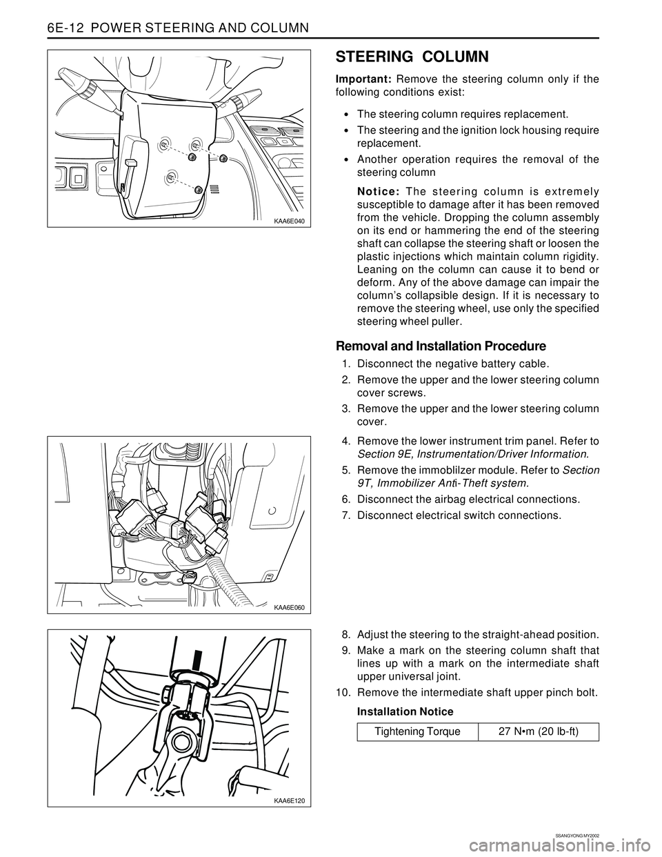
STEERING COLUMN
Important: Remove the steering column only if the
following conditions exist:
The steering column requires replacement.
The steering and the ignition lock housing require
replacement.
Another operation requires the removal of the
steering column
Notice: The steering column is extremely
susceptible to damage after it has been removed
from the vehicle. Dropping the column assembly
on its end or hammering the end of the steering
shaft can collapse the steering shaft or loosen the
plastic injections which maintain column rigidity.
Leaning on the column can cause it to bend or
deform. Any of the above damage can impair the
column’s collapsible design. If it is necessary to
remove the steering wheel, use only the specified
steering wheel puller.
Removal and Installation Procedure
1. Disconnect the negative battery cable.
2. Remove the upper and the lower steering column
cover screws.
3. Remove the upper and the lower steering column
cover.
KAA6E060
4. Remove the lower instrument trim panel. Refer to
Section 9E, Instrumentation/Driver Information.
5. Remove the immoblilzer module. Refer to Section
9T, Immobilizer Anti-Theft system.
6. Disconnect the airbag electrical connections.
7. Disconnect electrical switch connections.
8. Adjust the steering to the straight-ahead position.
9. Make a mark on the steering column shaft that
lines up with a mark on the intermediate shaft
upper universal joint.
10. Remove the intermediate shaft upper pinch bolt.
Installation Notice
Tightening Torque 27 Nm (20 lb-ft)
Page 1525 of 2053
SSANGYONG MY2002
7A-24 HEATING AND VENTILATION SYSTEM
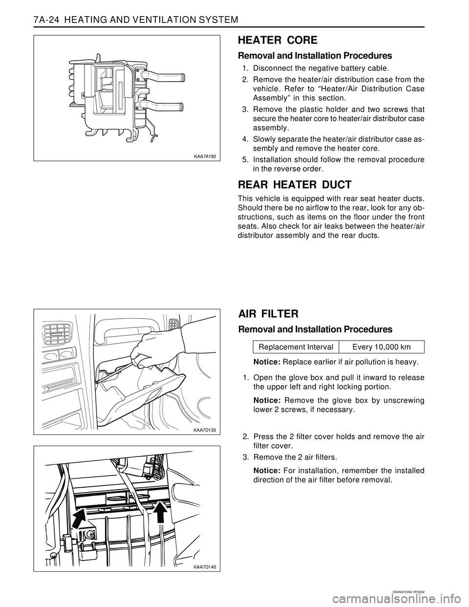
HEATER CORE
Removal and Installation Procedures
1. Disconnect the negative battery cable.
2. Remove the heater/air distribution case from the
vehicle. Refer to “Heater/Air Distribution Case
Assembly” in this section.
3. Remove the plastic holder and two screws that
secure the heater core to heater/air distributor case
assembly.
4. Slowly separate the heater/air distributor case as-
sembly and remove the heater core.
5. Installation should follow the removal procedure
in the reverse order.
REAR HEATER DUCT
This vehicle is equipped with rear seat heater ducts.
Should there be no airflow to the rear, look for any ob-
structions, such as items on the floor under the front
seats. Also check for air leaks between the heater/air
distributor assembly and the rear ducts.
KAA7A190
KAA7D130
KAA7D140
AIR FILTER
Removal and Installation Procedures
Notice: Replace earlier if air pollution is heavy.
1. Open the glove box and pull it inward to release
the upper left and right locking portion.
Notice: Remove the glove box by unscrewing
lower 2 screws, if necessary.
2. Press the 2 filter cover holds and remove the air
filter cover.
3. Remove the 2 air filters.
Notice: For installation, remember the installed
direction of the air filter before removal.
Replacement Interval Every 10,000 km
Page 1530 of 2053
SECTION 7C
MANUAL CONTROL / SEMIAUTO
TEMPERATURE CONTROL HEATING,
VENTILATION AND AIR CONDITIONING
SYSTEM
CAUTION: Disconnect the negative battery cable before removing or installing any electrical unit or when
a tool or equipment could easily come in contact with exposed electrical terminals. Disconnecting this
cable will help prevent personal injury and damage to the vehicle. The ignition must also be in LOCK
unless other-wise noted.
TABLE OF CONTENTS
Specifications.......................................................7C-2
Refrigerant..........................................................7C-2
Evaporator Unit....................................................7C-2
Blower Unit..........................................................7C-2
Compressor.........................................................7C-2
Condenser...........................................................7C-2
Receiver Drier......................................................7C-2
Pressure Switch...................................................7C-3
Air Filter...............................................................7C-3
Heater Unit..........................................................7C-3
Fastener Tightening Specifications.......................7C-3
Diagnosis..............................................................7C-4
Defectives in Fan Motor Circuit.............................7C-5
Defectives in Compressor Circuit.........................7C-6
Diagnosis Using the Manifold Gauge...................7C-7Component Locator.............................................7C-9
Ventilation............................................................7C-9
Heater System ................................................... 7C-11
Air Conditioner System...................................... 7C-12
Diesel Engine .................................................... 7C-12
Gasoline Engine................................................ 7C-13
Maintenance and Repair................................... 7C-14
Refrigerant Charging .......................................... 7C-14
Compressor Oil Replacement............................ 7C-18
Repair Instructions.............................................. 7C-19
On-Vehicle Service............................................... 7C-19
Condener.......................................................... 7C-19
Receiver Drier.................................................... 7C-21
Air - Conditioner Compressor............................. 7C-23
Heater and Air Conditioner Control Box.............. 7C-24
Air Filter............................................................. 7C-25
Page 1586 of 2053
SECTION 8B
SUPPLEMENTAL RESTRAINTS SYSTEM
CAUTION: Disconnect the negative battery cable before removing or installing any electrical unit or when a
tool or equipment could easily come in contact with exposed electrical terminals. Disconnecting this cable
will help prevent personal injury and damage to the vehicle. The ignition must also be in LOCK unless
other-wise noted.
TABLE OF CONTENTS
Description and Operation...................................8B-3
Supplemental Restraint System (SRS)..................8B-3
Airbag Modules...................................................8B-3
Front Seat Belt Pretensioners...............................8B-4
Sensing and Diagnostic Module (SDM)................8B-4
Airbag Warning Lamp ..........................................8B-5
Clock Spring........................................................8B-5
Wiring Harness Connectors..................................8B-5
Components Locator............................................8B-6
SRS Component and Wiring Location View...........8B-6
Diagnostic Information and Procedures..............8B-7
Diagnostic Trouble Codes (DTC)..........................8B-7
Scan Tool Diagnostics.........................................8B-7
Use of Special Tools............................................8B-7
Diagnostic Trouble Code Table............................8B-7
SRS Diagnostic System Check..........................8B-10
Sensing and Diagnostic Module (SDM)
Integrity Check...............................................8B-12
Airbag Warning Lamp Stays on with Ignition
Switch ON......................................................8B-14
DTCs - Internal Fault..........................................8B-16
DTCs 01 Driver Deployment Loop Shorted to
Voltage...........................................................8B-18
DTC 02 Passenger Deployment Loop Shorted to
Voltage...........................................................8B-20
DTC 03 Driver Seat Belt Pretensioner Shorted to
Voltage...........................................................8B-22
DTC 04 Passenger Seat Belt Pretensioner
Shorted to Voltage..........................................8B-24
DTC 05 Driver Deployment Loop Shorted to
Ground...........................................................8B-26
DTC 06 Passenger Deployment Loop Shorted to
Ground...........................................................8B-28
DTC 07 Driver Seat Belt Pretensioner Shorted to
Ground...........................................................8B-30DTC 08 Passenger Seat Belt Pretensioner
Shorted to Ground ..........................................8B-32
DTC 17 Driver Deployment Loop
Resistance High.............................................8B-34
DTC 18 Passenger Deployment Loop
Resistance High.............................................8B-38
DTC 19 Driver Seat Belt Pretensioner
Deployment Loop resistance High...................8B-40
DTC 20 Passenger Seat Belt Pretensioner
Deployment Loop Resistance High.................8B-42
DTC 21 Driver Airbag Deployment Loop
Resistance Low..............................................8B-44
DTC 22 Passenger Airbag Deployment Loop
Resistance Low..............................................8B-48
DTC 23 Driver Seat Belt Pretensioner
Deployment Loop resistance Low....................8B-50
DTC 24 Passenger Seat Belt Pretensioner
Deployment Loop Resistance Low..................8B-52
DTC 46 Airbag Warning Lamp Circuit Open or
Short to Ground/Battery..................................8B-54
DTC 47 Battery Voltage is Out of
Specification...................................................8B-56
Repair Instruction...............................................8B-58
On-Vehicle Service...............................................8B-58
Service Precaution.............................................8B-58
Disabling the Supplemental Restraint
System (SRS).................................................8B-58
Enabling the Supplemental Restraint
System (SRS).................................................8B-58
Handling, Installation and Diagnosis..................8B-58
Repairs and Inspections Required After an
Accident ........................................................8B-58
Accident with Deployment - Components
Replacement..................................................8B-58
Accident without Deployment - Component
Inspection......................................................8B-59
Page 1649 of 2053
SUPPLEMENTAL RESTRAINTS SYSTEM 8B-67
SSANGYONG MY2002
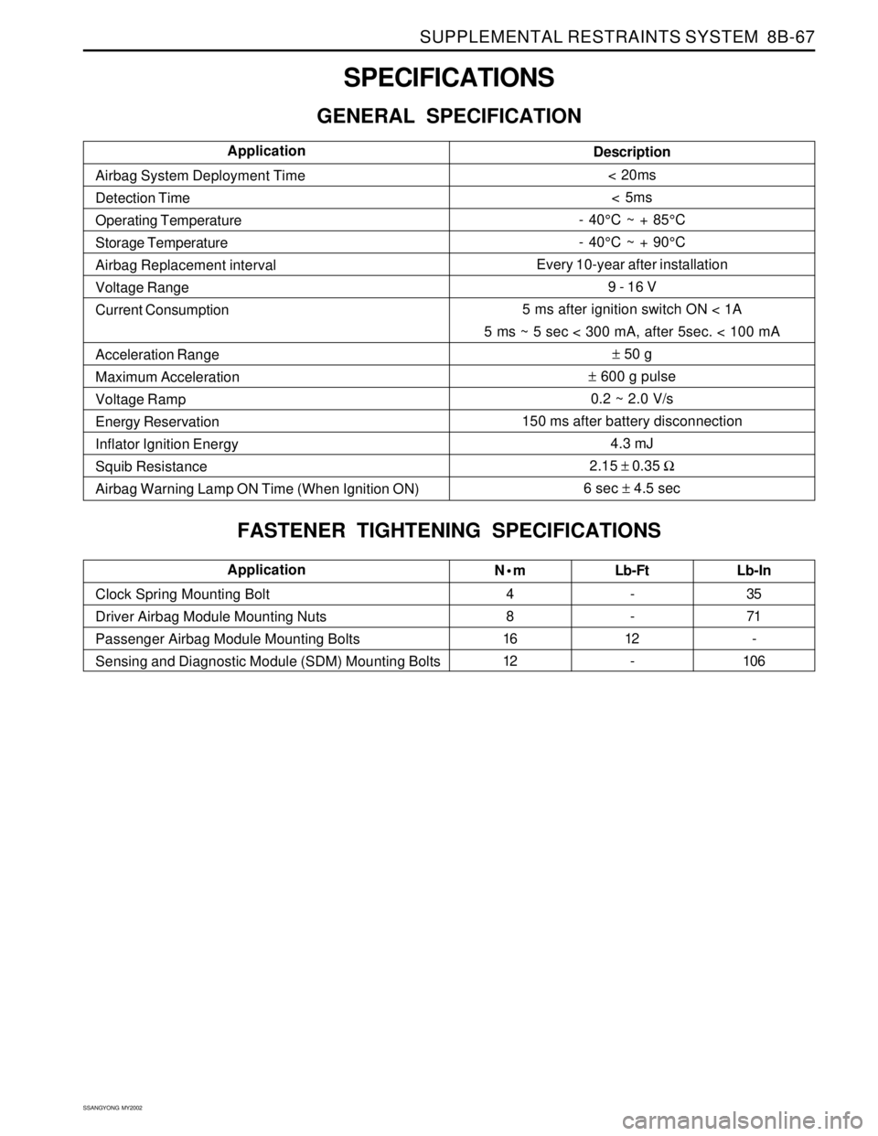
SPECIFICATIONS
GENERAL SPECIFICATION
Nm
4
8
16
12Lb-Ft
-
-
12
- Clock Spring Mounting Bolt
Driver Airbag Module Mounting Nuts
Passenger Airbag Module Mounting Bolts
Sensing and Diagnostic Module (SDM) Mounting BoltsLb-In
35
71
-
106Application
Description
< 20ms
< 5ms
- 40°C ~ + 85°C
- 40°C ~ + 90°C
Every 10-year after installation
9 - 16 V
5 ms after ignition switch ON < 1A
5 ms ~ 5 sec < 300 mA, after 5sec. < 100 mA
± 50 g
± 600 g pulse
0.2 ~ 2.0 V/s
150 ms after battery disconnection
4.3 mJ
2.15 ± 0.35 Ω
6 sec ± 4.5 sec Airbag System Deployment Time
Detection Time
Operating Temperature
Storage Temperature
Airbag Replacement interval
Voltage Range
Current Consumption
Acceleration Range
Maximum Acceleration
Voltage Ramp
Energy Reservation
Inflator Ignition Energy
Squib Resistance
Airbag Warning Lamp ON Time (When Ignition ON)Application
FASTENER TIGHTENING SPECIFICATIONS