1997 SSANGYONG KORANDO battery location
[x] Cancel search: battery locationPage 32 of 2053

1A1 -- 12 GENERAL ENGINE INFORMATION
D AEW OO M Y_2000
GENERAL INFORMATION
CLEANLINESS AND CARE
An automobile engine is a combination of many ma-
chined, honed, polished and lapped surfaces with toler-
ances that are measured in the ten-thousandths of an
inch. When any internal engine parts are serviced, care
and cleanliness are important. A liberal coating of enigne
oil should be applied to friction areas during assembly, to
protect and lubricate the surfaces on initial operation.
Proper cleaning and protection of machined surfaces and
friction areas is part of the repair procedure. This is con-
sidered standard shop practice even if not specifically
stated.
Whenever valve train components are removed for ser-
vice, they should be kept in order. They should be
installed in the same locations, and with the same mating
surfaces, as when they were removed.
Battery cables should be disconnected before any major
work is performed on the engine. Failure to disconnectcables may result in damage to wire harness or other
electrical parts.
ON-ENGINE SERVICE
Caution: Disconnect the negative battery cable be -
fore removing or installing any electrical unit, or
when a tool or equipment could easily come in con-
tact with exposed electrical terminals. Disconnect -
ing this cable will help prevent personal injury and
damage to the vehicle. The ignition must also be in
LOCK unless otherwise noted.
Notice:Any time the air cleaner is removed, the intake
opening should be covered. Thiswill protect against ac-
cidental entrance of foreign material, which could follow
the intake passage into the cylinder and cause exten-
sive damage when the engine is started.
Page 285 of 2053

GENERAL ENGINE INFORMATION 1A2 -- 13
D AEW OO M Y_2000
GENERAL INFORMATION
CLEANLINESS AND CARE
An automobile engine is a combination of many ma-
chined, honed, polished and lapped surfaces with toler-
ances that are measured in the ten-thousandths of an
inch. When any internal engine parts are serviced, care
and cleanliness are important. A liberal coating of enigne
oil should be applied to friction areas during assembly, to
protect and lubricate the surfaces on initial operation.
Proper cleaning and protection of machined surfaces and
friction areas is part of the repair procedure. This is con-
sidered standard shop practice even if not specifically
stated.
Whenever valve train components are removed for ser-
vice, they should be kept in order. They should be
installed in the same locations, and with the same mating
surfaces, as when they were removed.
Battery cables should be disconnected before any major
work is performed on the engine. Failure to disconnect
cables may result in damage to wire harness or other
electrical parts.
ON-ENGINE SERVICE
Caution: Disconnect the negative battery cable be -
fore removing or installing any electrical unit, or
when a tool or equipment could easily come in con-
tact with exposed electrical terminals. Disconnect -
ing this cable will help prevent personal injury and
damage to the vehicle. The ignition must also be in
LOCK unless otherwise noted.
Notice:Any time the air cleaner is removed, the intake
opening should be covered. Thiswill protect against ac-
cidental entrance of foreign material, which could follow
the intake passage into the cylinder and cause exten-
sive damage when the engine is started.
Page 550 of 2053
GENERAL ENGINE INFORMATION 1A3 -- 15
D AEW OO M Y_2000
GENERAL INFORMATION
CLEANLINESS AND CARE
An automobile engine is a combination of many ma-
chined, honed, polished and lapped surfaces with toler-
ances that are measured in the ten-- thousanths of an
inch. When any internal engine parts are serviced, care
and cleanliness are important. A liberal coating of en-
igne oil should be applied to friction areas during assem-
bly, to protect and lubricate the surfaces on initial
operation. Proper cleaning and protection of machined
surfaces and friction areas is part fo the repair proce-
dure. This is considered standard shop practice even if
not specifically stated.
Whenever valve train components are removed for ser-
vice, they should be kept in order. They should be
installed in the same locations, and with the same mat-
ing surfaces, as when they were removed.
Battery cables should be disconnected before any major
work is performed on the engine. Failure to disconnectcables may result in damage to wire harness or other
electrical parts.
ON-- ENGINE SERVICE
Caution: Disconnect the negative battery cable be -
fore removing or installing any electrical unit, or
when a tool or equipment could easily come in con-
tact with exposed electrical terminals. Disconnect -
ing this cable will help prevent personal injury and
damage to the vehicle. The ignition must also be in
LOCK unless otherwise noted.
Notice:Any time the air cleaner is removed, the intake
opening should be covered. Thiswill protect against ac-
cidental entrance of foreign material, which could follow
the intake passage into the cylinder and cause exten-
sive damage when the engine is started.
Page 1082 of 2053
ABS AND TCS 4F-99
SSANGYONG MY2002
REPAIR INSTRUCTIONS
ON-VEHICLE SERVICE
SERVICE PRECAUTIONS
Caution: Brake Fluid may irritate eyes and skin. In
case of contact, take the following actions:
Eye contact - rinse thoroughly with water.
Skin contact - wash with soap and water.
Ingestion - consult a physician immediately.
Caution: To help avoid personal injury due to poor
braking. DO NOT Tap into the vehicle’s brake system
to operate a trailer brake system.
Notice: When fasteners are removed, always reinstall
them at the same location from which they were
removed. If a fastener needs to be replaced, use the
correct part number fastener for is not available, a
fastener of equal size and strength (or stronger) may
be used. Fasteners that are not reused, and those
requiring thread-locking compound will be called out.
The correct torque values must be used when installing
fasteners that require them. If the above procedures
are not followed, parts or system damage could result.
Notice: Use only DOT-3 equivalent hydraulic brake
fluid. The use of DOT-5 (silicone) brake fluid is not
recommended. Reduced brake performance or
durability may result.
Notice: Avoid spilling brake fluid on any the vehicle’s
painted surfaces, wiring, cables or electrical
connectors. Brake fluid will damage paint and electrical
connections. If any fluid is spilled on the vehicle, flush
the area with water to lessen the damage.
Electronic System Service Precautions
Take care to avoid electronic brake control module
(EBCM) circuit overloading. In testing for opens or
shorts, do not ground or apply voltage to any circuit
unless instructed to do so by the diagnostic procedure.
Test circuits only with a high-impedance multi-meter.
Never remove or apply power to any control module
with the ignition switch in the ON position. Always turn
the ignition to the OFF position before removing or
connecting battery cables, fuses or connectors.
General Service Precautions
Disconnect the EBCM connector before performing any
vehicle welding work using an electric arc welder.
Do not attempt to disassemble any component
designated as nonserviceable. The hydraulic modulator
and the EBCM can be separated from each other and
replaced separately but cannot be serviced. They have
no replaceable parts, and there is no replaceable parts,
and there is no access to the components they contain.
Bleeding System
Replacement modulators are shipped already filled
and bled. In normal procedures requiring removal of
the modulator, such as to replace the EBCM, air will
not enter the modulator, and normal bleeding will be
all that is needed.
If air enters the hydraulic modulator, or if an unfilled
modulator is installed, use the brake bleeding program
in the scan tool to bleed the modulator. Manual
bleeding of the hydraulic modulator is not possible.
Page 1132 of 2053
5A-38 AUTOMATIC TRANSMISSION
SSANGYONG MY2002
DIAGNOSIS
BASIC KNOWLEDGE REQUIRED
You must be familliar with some basic electronics to
use this section of the Service Manual. They will help
you to follow diagnostic procedures.
Notice: Lack of the basic knowledge of this transmis-
sion when performing diagnostic procedures could re-
sult in incorrect diagnostic performance or damage to
transmission components. Do not, under any circum-
stances, attempt to diagnose a transmission problem
without this basic knowledge.
Notice: If a wire is probed with a sharp instrument
and not properly sealed afterward, the wire will corrode
and an open circuit will result.
Diagnostic test probes are now available that allow
you to probe individual wires without leaving the wire
open to the environment. These probe devices are
inexpensive and easy to install, and they permanently
seal the wire from corrosion.
Special Tools
You should be able to use a Digital Volt Meter (DVM),
a circuit tester, jumper wires or leads and a line
pressure gauge set. The functional check procedure
is designed to verify the correct operation of electronic
components in the transmission. This will eliminate the
unnecessary removal of transmission components.
FUNCTIONAL CHECK
PROCEDURE
Begin with the Functional Check Procedure which pro-
vides a general outline of how to diagnose automatic
transmission. The following functional check procedure
will indicate the proper path of diagnosing the transmis-
sion by describing the basic checks and then referenc-
ing the locations of the specific checks.
Check the fluid level according to the Fluid Level
Service Procedure.
Check the transmission fluid leak.
Check if the transmission fluid is not burnt by smell.
Notice: The specific fluid used in this transmission
turns brown during normal operation. Brown fluid
does not indicate a transmission fault.
Ensure that the transmission is not in Limp Home
Mode (LHM).
Check the battery terminals and the earth connec-
tions for corrosion or looseness.
Check that the cooler flow is not restricted.
Check all electrical plug connections for tightness.
Use on-board diagnostic tool or a scan tool to see
if any transmission trouble codes have been set.
DIAGNOSTIC INFORMATION AND PROCEDURES
Refer to the appropriate “Diagnostic Trouble Code
(DTC)” information and repair the vehicle as
directed. After repairing the vehicle, perform the
road test and verify that the code has not set again.
Perform the Electrical/Garage Shift Tests.
Perform the Road Test Procedure in this section.
Inspect the oil and check for metal or other contami-
nants in the oil pan.
TRANSMISSION FLUID LEVEL
SERVICE PROCEDURE
This procedure is to be used when checking a concern
with the fluid level in a vehicle. A low fluid level will
result in slipping and loss of drive/ reverse or delay on
engagement of drive/ reverse when the vehicle is cold.
The vehicle is first checked for transmission diagnostic
messages on the scan tool. If the oil level is low, it is
possible to register a vehicle speed signal fault.
The vehicle is to be test driven to determine if there is
an abnormal delay when selecting drive or reverse, or
loss of drive. One symptom of low fluid level is a
momentary loss of drive when driving the vehicle around
a corner. Also when the transmission fluid level is low,
a loss of drive may occur when the transmission fluid
temperature is low.
If there is no loss of drive when the vehicle is driven
warm and a vehicle speed signal fault is registered,
then fluid should be added to the transmission.
When adding or changing transmission fluid use only
Castrol TQ 95 automatic transmission fluid. The use of
incorrect fluid will cause the performance and durability
of the transmission to be severely degraded.
Fluid Level Diagnosis procedure
1. If the vehicle is at operating temperature allow the
vehicle to cool down for two hours, but no greater
than four hours. Or if the vehicle is at cool status,
start the engine and allow the engine to idle for
approximately 5 minutes or, if possible, drive the
vehicle for a few kilometers. This will allow the
transmission to be within the correct temperature
range. Transmission fluid level should be checked
at temperature 50 - 60 °C (82 - 140 °F).
Caution: Removal of the fluid filler plug when
the transmission fluid is hot may cause injury if
fluid drains from the filler hole.
2. With the brake pedal pressed, move the gear shift
control lever through the gear ranges, pausing a
few seconds in each range. Return the gear shift
control lever to P (Park). Turn the engine OFF.
3. Park the vehicle on a hoist, inspection pit or similar
raised level surface. The vehicle must be control
level to obtain a correct fluid level measurement.
Page 1391 of 2053
TRANSFER CASE 5D1-69
SSANGYONG MY2002
KAA5D320
KAA5D330
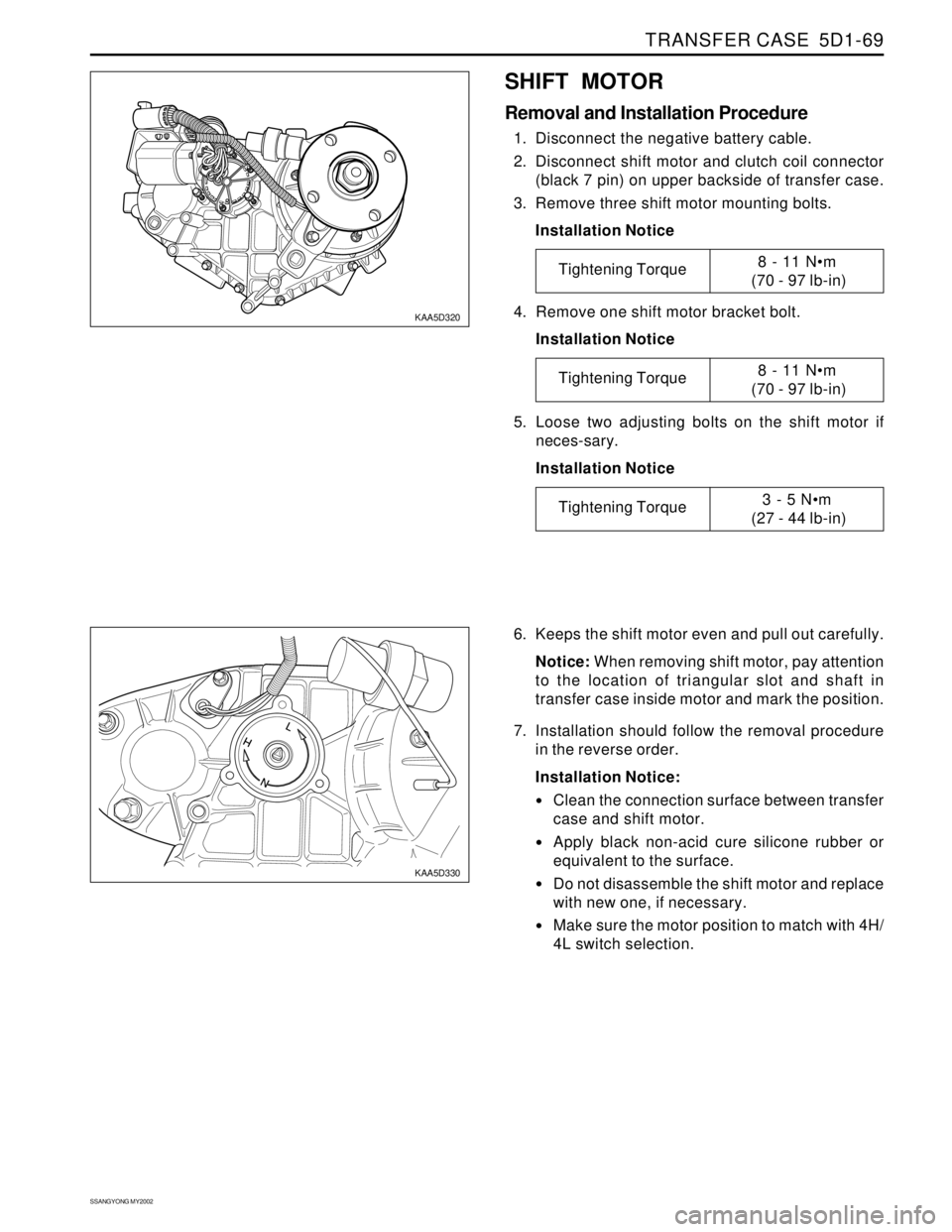
SHIFT MOTOR
Removal and Installation Procedure
1. Disconnect the negative battery cable.
2. Disconnect shift motor and clutch coil connector
(black 7 pin) on upper backside of transfer case.
3. Remove three shift motor mounting bolts.
Installation Notice
6. Keeps the shift motor even and pull out carefully.
Notice: When removing shift motor, pay attention
to the location of triangular slot and shaft in
transfer case inside motor and mark the position.
7. Installation should follow the removal procedure
in the reverse order.
Installation Notice:
Clean the connection surface between transfer
case and shift motor.
Apply black non-acid cure silicone rubber or
equivalent to the surface.
Do not disassemble the shift motor and replace
with new one, if necessary.
Make sure the motor position to match with 4H/
4L switch selection. 4. Remove one shift motor bracket bolt.
Installation Notice
5. Loose two adjusting bolts on the shift motor if
neces-sary.
Installation Notice
Tightening Torque8 - 11 Nm
(70 - 97 lb-in)
Tightening Torque8 - 11 Nm
(70 - 97 lb-in)
Tightening Torque3 - 5 Nm
(27 - 44 lb-in)
Page 1586 of 2053
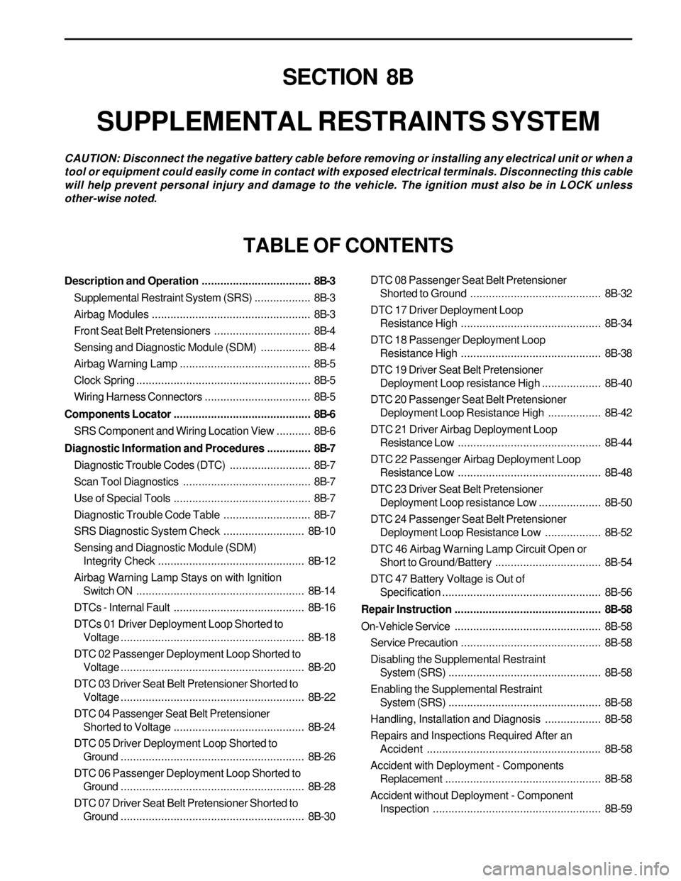
SECTION 8B
SUPPLEMENTAL RESTRAINTS SYSTEM
CAUTION: Disconnect the negative battery cable before removing or installing any electrical unit or when a
tool or equipment could easily come in contact with exposed electrical terminals. Disconnecting this cable
will help prevent personal injury and damage to the vehicle. The ignition must also be in LOCK unless
other-wise noted.
TABLE OF CONTENTS
Description and Operation...................................8B-3
Supplemental Restraint System (SRS)..................8B-3
Airbag Modules...................................................8B-3
Front Seat Belt Pretensioners...............................8B-4
Sensing and Diagnostic Module (SDM)................8B-4
Airbag Warning Lamp ..........................................8B-5
Clock Spring........................................................8B-5
Wiring Harness Connectors..................................8B-5
Components Locator............................................8B-6
SRS Component and Wiring Location View...........8B-6
Diagnostic Information and Procedures..............8B-7
Diagnostic Trouble Codes (DTC)..........................8B-7
Scan Tool Diagnostics.........................................8B-7
Use of Special Tools............................................8B-7
Diagnostic Trouble Code Table............................8B-7
SRS Diagnostic System Check..........................8B-10
Sensing and Diagnostic Module (SDM)
Integrity Check...............................................8B-12
Airbag Warning Lamp Stays on with Ignition
Switch ON......................................................8B-14
DTCs - Internal Fault..........................................8B-16
DTCs 01 Driver Deployment Loop Shorted to
Voltage...........................................................8B-18
DTC 02 Passenger Deployment Loop Shorted to
Voltage...........................................................8B-20
DTC 03 Driver Seat Belt Pretensioner Shorted to
Voltage...........................................................8B-22
DTC 04 Passenger Seat Belt Pretensioner
Shorted to Voltage..........................................8B-24
DTC 05 Driver Deployment Loop Shorted to
Ground...........................................................8B-26
DTC 06 Passenger Deployment Loop Shorted to
Ground...........................................................8B-28
DTC 07 Driver Seat Belt Pretensioner Shorted to
Ground...........................................................8B-30DTC 08 Passenger Seat Belt Pretensioner
Shorted to Ground ..........................................8B-32
DTC 17 Driver Deployment Loop
Resistance High.............................................8B-34
DTC 18 Passenger Deployment Loop
Resistance High.............................................8B-38
DTC 19 Driver Seat Belt Pretensioner
Deployment Loop resistance High...................8B-40
DTC 20 Passenger Seat Belt Pretensioner
Deployment Loop Resistance High.................8B-42
DTC 21 Driver Airbag Deployment Loop
Resistance Low..............................................8B-44
DTC 22 Passenger Airbag Deployment Loop
Resistance Low..............................................8B-48
DTC 23 Driver Seat Belt Pretensioner
Deployment Loop resistance Low....................8B-50
DTC 24 Passenger Seat Belt Pretensioner
Deployment Loop Resistance Low..................8B-52
DTC 46 Airbag Warning Lamp Circuit Open or
Short to Ground/Battery..................................8B-54
DTC 47 Battery Voltage is Out of
Specification...................................................8B-56
Repair Instruction...............................................8B-58
On-Vehicle Service...............................................8B-58
Service Precaution.............................................8B-58
Disabling the Supplemental Restraint
System (SRS).................................................8B-58
Enabling the Supplemental Restraint
System (SRS).................................................8B-58
Handling, Installation and Diagnosis..................8B-58
Repairs and Inspections Required After an
Accident ........................................................8B-58
Accident with Deployment - Components
Replacement..................................................8B-58
Accident without Deployment - Component
Inspection......................................................8B-59
Page 1590 of 2053
SUPPLEMENTAL RESTRAINTS SYSTEM 8B-5
SSANGYONG MY2002
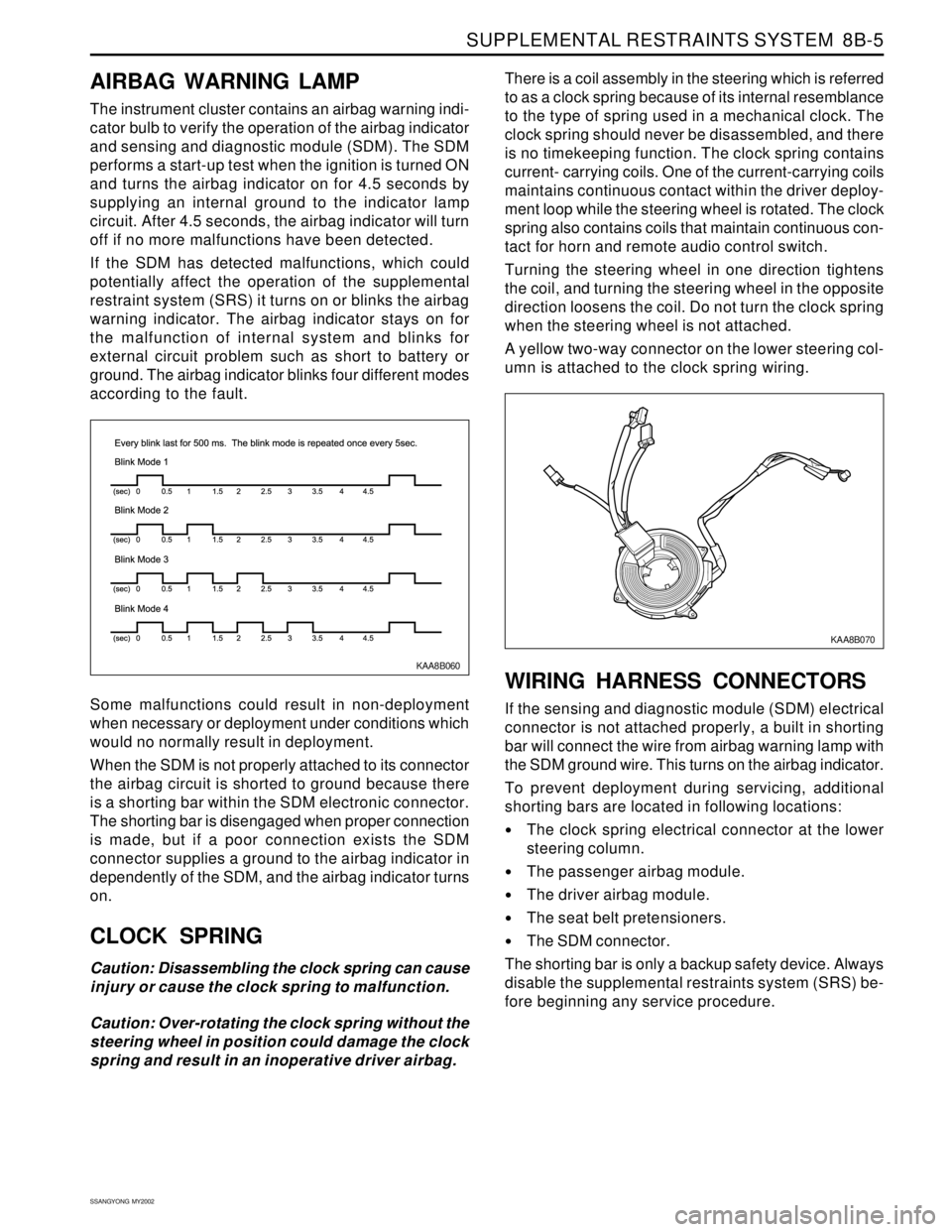
KAA8B060
AIRBAG WARNING LAMP
The instrument cluster contains an airbag warning indi-
cator bulb to verify the operation of the airbag indicator
and sensing and diagnostic module (SDM). The SDM
performs a start-up test when the ignition is turned ON
and turns the airbag indicator on for 4.5 seconds by
supplying an internal ground to the indicator lamp
circuit. After 4.5 seconds, the airbag indicator will turn
off if no more malfunctions have been detected.
If the SDM has detected malfunctions, which could
potentially affect the operation of the supplemental
restraint system (SRS) it turns on or blinks the airbag
warning indicator. The airbag indicator stays on for
the malfunction of internal system and blinks for
external circuit problem such as short to battery or
ground. The airbag indicator blinks four different modes
according to the fault.
Some malfunctions could result in non-deployment
when necessary or deployment under conditions which
would no normally result in deployment.
When the SDM is not properly attached to its connector
the airbag circuit is shorted to ground because there
is a shorting bar within the SDM electronic connector.
The shorting bar is disengaged when proper connection
is made, but if a poor connection exists the SDM
connector supplies a ground to the airbag indicator in
dependently of the SDM, and the airbag indicator turns
on.
CLOCK SPRING
Caution: Disassembling the clock spring can cause
injury or cause the clock spring to malfunction.
Caution: Over-rotating the clock spring without the
steering wheel in position could damage the clock
spring and result in an inoperative driver airbag.There is a coil assembly in the steering which is referred
to as a clock spring because of its internal resemblance
to the type of spring used in a mechanical clock. The
clock spring should never be disassembled, and there
is no timekeeping function. The clock spring contains
current- carrying coils. One of the current-carrying coils
maintains continuous contact within the driver deploy-
ment loop while the steering wheel is rotated. The clock
spring also contains coils that maintain continuous con-
tact for horn and remote audio control switch.
Turning the steering wheel in one direction tightens
the coil, and turning the steering wheel in the opposite
direction loosens the coil. Do not turn the clock spring
when the steering wheel is not attached.
A yellow two-way connector on the lower steering col-
umn is attached to the clock spring wiring.
WIRING HARNESS CONNECTORS
If the sensing and diagnostic module (SDM) electrical
connector is not attached properly, a built in shorting
bar will connect the wire from airbag warning lamp with
the SDM ground wire. This turns on the airbag indicator.
To prevent deployment during servicing, additional
shorting bars are located in following locations:
The clock spring electrical connector at the lower
steering column.
The passenger airbag module.
The driver airbag module.
The seat belt pretensioners.
The SDM connector.
The shorting bar is only a backup safety device. Always
disable the supplemental restraints system (SRS) be-
fore beginning any service procedure.
KAA8B070