1997 SSANGYONG KORANDO clearance automatic
[x] Cancel search: clearance automaticPage 22 of 2053

1A1 -- 2 GENERAL ENGINE INFORMATION
D AEW OO M Y_2000
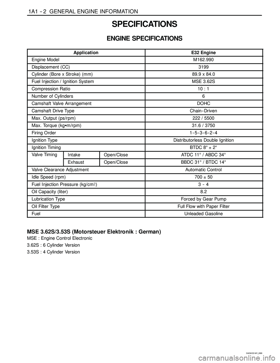
SPECIFICATIONS
ENGINE SPECIFICATIONS
ApplicationE32 Engine
Engine ModelM162.990
Displacement (CC)3199
Cylinder (Bore x Stroke)(mm)89.9 x 84.0
Fuel Injection / Ignition SystemMSE 3.62S
Compression Ratio10 : 1
Number of Cylinders6
Camshaft Valve ArrangementDOHC
Camshaft Drive TypeChain-- Driven
Max. Output (ps/rpm)222 / 5500
Max. Torque (kgSm/rpm)31.6 / 3750
Firing Order1--5--3--6--2--4
Ignition TypeDistributorless Double Ignition
Ignition TimingBTDC 8°±2°
Valve TimingIntakeOpen/CloseAT DC 11°/ ABDC 34°g
ExhaustOpen/CloseBBDC 31°/BTDC14°
Valve Clearance AdjustmentAutomatic Control
Idle Speed (rpm)700±50
Fuel Injection Pressure (kg/cm@)3--4
Oil Capacity (liter)8.2
Lubrication TypeForced by Gear Pump
Oil Filter TypeFull Flow with Paper Filter
FuelUnleaded Gasoline
MSE 3.62S/3.53S (Motorsteuer Elektronik : German)
MSE : Engine Control Electronic
3.62S : 6 Cylinder Version
3.53S : 4 Cylinder Version
Page 286 of 2053

1A2 -- 2 GENERAL ENGINE INFORMATION
D AEW OO M Y_2000
SPECIFICATIONS
ENGINE SPECIFICATIONS
ApplicationE23 EngineE20 Engine
Engine ModelM161.970M161.940
Displacement (CC)22951998
Cylinder (Bore x Stroke)(mm)90.9 x 88.489.9 x 78.7
Fuel Injection / Ignition SystemMSE 3.53S←
Compression Ratio10.4:19.6:1
Number of Cylinders4←
Camshaft Valve ArrangementDOHC←
Camshaft Drive TypeChain-- Driven←
Max. Output (ps/rpm)149 / 5500135 / 5500
Max. Torque (kgSm/rpm)22.4 / 400019.3 / 4000
Firing Order1--3--4--2←
Ignition TypeDistributorless←
Ignition TimingBTDC 6°±2°←
Va lv e
Tii
IntakeOpen/CloseATDC 19.25°/ ABDC 28.76°ATDC 13.15°/ ABDC 13.57°
Tim in gExhaustOpen/CloseBBDC 20.62°/ BTDC 15.08°BBDC 16.58°/ BTDC 17.05°
Valve Clearance AdjustmentAutomatic Control←
Idle Speed (rpm)750±50←
Fuel Injection Pressure (kg/cm@)3.2 -- 4.2←
Oil Capacity (liter)7.5←
Lubrication TypeForced by Gear Pump←
Oil Filter TypeFull Flow with Paper Filter←
FuelUnleaded Gasoline←
MSE 3.62S/3.53S (Motorsteuer Elektronik : German)
MSE : Engine Control Electronic
3.62S : 6 cylinder version
3.53S : 4 cylinder version
Page 536 of 2053

D AEW OO M Y_2000
SECTION 1
ENGINE
SECTION 1A3 (OM600 ENGINE)
GENERAL ENGINE INFORMATION
TABLE OF CONTENTS
Specifications 1A3 -- 1............................
Engine Specifications 1A3-- 1.....................
Sectional View 1A3 -- 3............................
OM662LA Engine 1A3-- 3........................
OM661LA Engine 1A3-- 5........................
Performance Curve 1A3-- 7........................
OM662LA Engine 1A3-- 7........................
OM661LA Engine 1A3-- 8........................
Special Tools 1A3 -- 9.............................Special Tools Table 1A3-- 9.......................
Diagnosis 1A3 -- 10................................
Oil Leak Diagnosis 1A3-- 10.......................
Compression Pressure Test 1A3-- 11..............
Cylinder Pressure Leakage Test 1A3-- 13...........
General Information 1A3 -- 15......................
Cleanliness and Care 1A3 -- 15....................
On-- Engine Service 1A3-- 15......................
SPECIFICATIONS
ENGINE SPECIFICATIONS
ApplicationOM662LAOM661LA
Engine TypeFour -- Stroke DieselFour -- Stroke Diesel
Displacement (CC)28742299
Cylinder (Bore x Stroke)(mm)89 x 92.489 x 92.4
Fuel Injection / Ignition SystemPES 5 M55 C320 RS 168PES 5 M55 C320 RS 167
Compression Ratio22 :122 :1
Number of Cylinders54
Camshaft Valve ArrangementSOHCSOHC
Camshaft Drive TypeChain -- DriveChain-- Drive
Max. Output (ps/rpm)120 / 4000101 / 4000
Max. Torque (kgSm/rpm)25.5 / 400021.5 / 2400
Firing Order1--2--4--5--31--3--4--2
Injection TimingBTDC 18_±10_BTDC 18_±10_
Valve Timing
(t2lift)
IntakeOpen/CloseAT DC 11 . 3 3_/ ABDC 17_AT DC 11 . 3 3_/ ABDC 17_g
(at 2mm lift)ExhaustOpen/CloseBBDC 28_/ BTDC 15.25_BBDC 28_/ BTDC 15.25_
Valve Clearance AdjustmentAutomatic ControlAutomatic Control
Page 962 of 2053

SSANGYONG MY2002
4E-2 REAR BRAKES
DESCRIPTION AND OPERATION
DRUM BRAKE
This drum brake assembly is a leading/trailing shoe
design.
Both brake shoes are held against the wheel cylinder
pistons by the lower return spring and the fixed anchor
plate near the lower return spring. When the brakes
are applied, the wheel cylinder pistons move both
shoes out to contact the drum. With forward wheel
rotation, the forward brake shoe will wrap into the drum
and become selt-energized. With reverse wheel
rotation, brake shoes is transferred to the anchor plate
through the braking plate to the axle flange.
Adjustment is automatic and occurs on any service
brake application. Do not switch the position of shoes
that have been in service, as this may render the self-
adjustment feature inoperative and result in increased
pedal travel.
The brake drum must have high abrasion resistance,
heatproof, high stiffness, fatigue stiffness and strength
enough not to make any deformation. The temperature
of the drum surface comes up to 500 - 700 °C on brake
operation by the friction with the lining. When the
temperature of the drum surface continues to keep
high, the friction coefficient goes down and the ‘fade
development’ occurs. When the brake is applied often
on the hill, any accident may be occur.
YAD4C010
Wheel Cylinder
Both wheel cylinder diameters are same in order to
balance the friction forces of both shoes.
The hydraulic pressure from the master cylinder is
provided to the wheel cylinder and the piston in the
wheel cylinder allows to push both shoes toward the
drum resulted in generating the braking force.
Brake Lining
The brake lining is installed with the brake shoe and
pushed toward the drum for applying the brake pedal.
Thus, lining must have high-heat tolerance, abrasion
resistance and high friction coefficient.
Brake Lining and Drum Clearance Automatic
Control System
If the lining’s wear is excessive, the piston moves to
long distance and the pedal travel increases. The
clearance between the drum and the brake lining
should be adjusted.
Generally the drum brake must be adjusted regularly
and thus the clearance automatic control system
enables to adjust the clearance between the brake
lining and the drum resulting from brake lining wear.
YAD4C020
1 Cylinder Housing
2 Boot
3 Spring
4 Piston Cup
5 Piston
6 Air Bleeder1 Cylinder Housing
2 Boot
3 Spring
4 Piston Cup
5 Piston
6 Air Bleeder
Page 965 of 2053

REAR BRAKES 4E-5
SSANGYONG MY2002
Lining Wear, Hardening
Oil or Water Contamination on the Lining
Inoperative Wheel Cylinder
Inoperative Clearance Automatic Control System
Lining Wear, Hardening
Oil or Water Contamination on the Lining
Inoperative Wheel Cylinder
Inoperative Clearance Automatic Control System
Damage of the Brake Shoe Return Spring
Inoperative Wheel Cylinder Returning
Lining Wear
Inoperative Clearance Automatic Control System
Lining Wear, Hardening
Foreign Material Inside Drum
Loosen the Brake Plate Bolt
Drum Deformation or Surface Damage
Lining Wear, Hardening
Oil Contamination on the Lining
Inoperative Clearance Automatic Control SystemReplace
Replace or Repair
Replace
Repair
Adjust
Replace or Repair
Replace
Repair
Replace
Replace
Replace
Repair
Replace
Clean
Tighten
Replace
Replace
Replace
Repair Poor Braking
Uneven Braking
Dragging Brake
Excessive Pedal Travel
Noise and Vibration When
Brake Applied
Inoperative Parking Brake
DIAGNOSTIC INFORMATION AND PROCEDURES
Symptom
Possible CauseAction
Page 970 of 2053

SSANGYONG MY2002
4E-10 REAR BRAKES
YAD4C280
COMPONENT LOCATOR
DRUM BRAKE
1 Bleeder Screw
2 Bleeder Screw Cap
3 Rear Brake Assembly
4 Rear Brake Plate
5 Wheel Cylinder
6 Strut Assembly (Clearance Automatic Control
System)
7 Brake Leading Shoe
8 Middle Return Spring9 Upper Return Spring
10 Brake Shoe Retaining Spring Pin
11 Trailing Shoe
12 Brake Shoe Retaining Spring
13 Brake Shoe Retaining Spring Cap
14 Lower Return Spring
15 Hub Bolt
16 Rear Brake Drum
Page 1139 of 2053

5A-44 AUTOMATIC TRANSMISSION
SSANGYONG MY2002
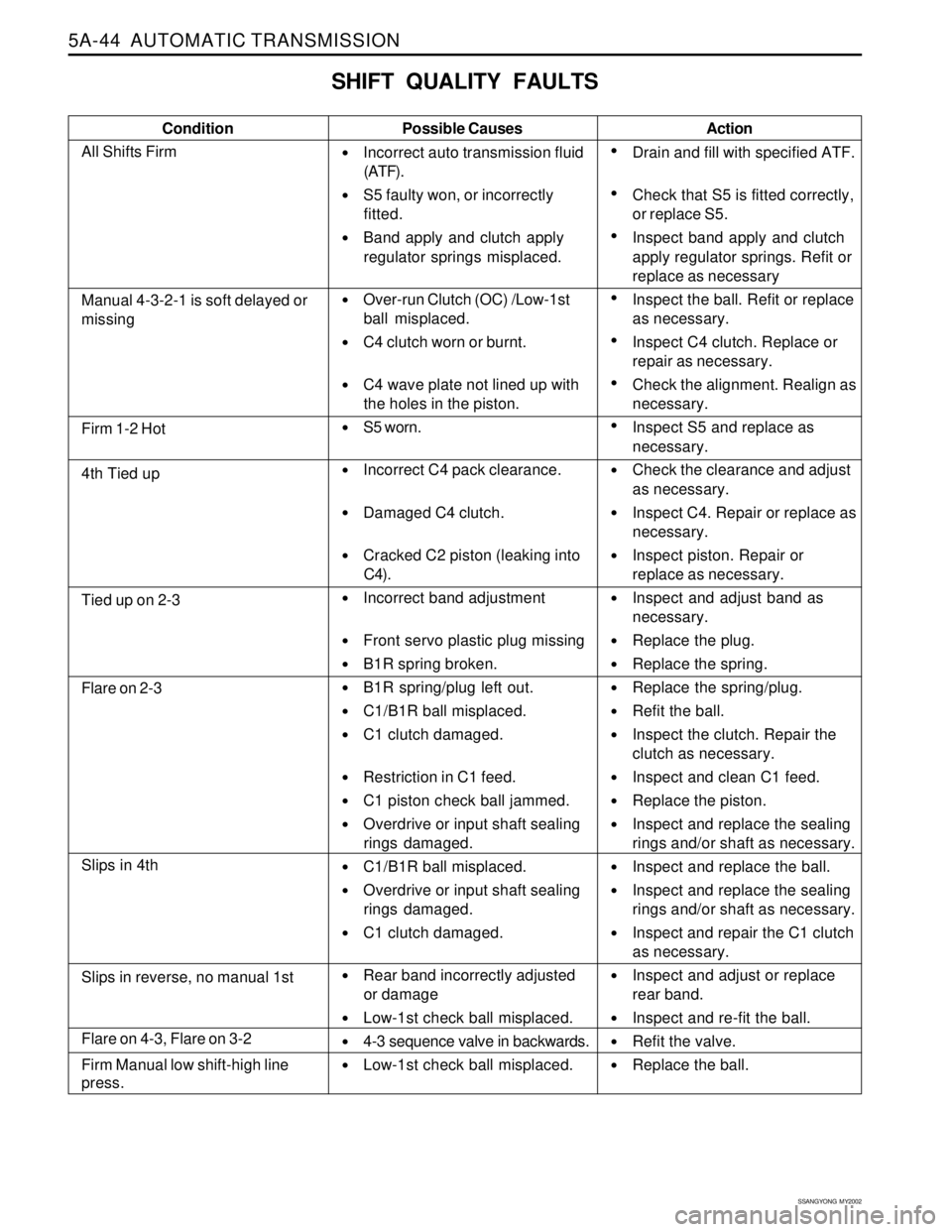
SHIFT QUALITY FAULTS
Condition Possible Causes
Incorrect auto transmission fluid
(ATF).
S5 faulty won, or incorrectly
fitted.
Band apply and clutch apply
regulator springs misplaced.
Over-run Clutch (OC) /Low-1st
ball misplaced.
C4 clutch worn or burnt.
C4 wave plate not lined up with
the holes in the piston.
S5 worn.
Incorrect C4 pack clearance.
Damaged C4 clutch.
Cracked C2 piston (leaking into
C4).
Incorrect band adjustment
Front servo plastic plug missing
B1R spring broken.
B1R spring/plug left out.
C1/B1R ball misplaced.
C1 clutch damaged.
Restriction in C1 feed.
C1 piston check ball jammed.
Overdrive or input shaft sealing
rings damaged.
C1/B1R ball misplaced.
Overdrive or input shaft sealing
rings damaged.
C1 clutch damaged.
Rear band incorrectly adjusted
or damage
Low-1st check ball misplaced.
4-3 sequence valve in backwards.
Low-1st check ball misplaced.Action
Drain and fill with specified ATF.
Check that S5 is fitted correctly,
or replace S5.
Inspect band apply and clutch
apply regulator springs. Refit or
replace as necessary
Inspect the ball. Refit or replace
as necessary.
Inspect C4 clutch. Replace or
repair as necessary.
Check the alignment. Realign as
necessary.
Inspect S5 and replace as
necessary.
Check the clearance and adjust
as necessary.
Inspect C4. Repair or replace as
necessary.
Inspect piston. Repair or
replace as necessary.
Inspect and adjust band as
necessary.
Replace the plug.
Replace the spring.
Replace the spring/plug.
Refit the ball.
Inspect the clutch. Repair the
clutch as necessary.
Inspect and clean C1 feed.
Replace the piston.
Inspect and replace the sealing
rings and/or shaft as necessary.
Inspect and replace the ball.
Inspect and replace the sealing
rings and/or shaft as necessary.
Inspect and repair the C1 clutch
as necessary.
Inspect and adjust or replace
rear band.
Inspect and re-fit the ball.
Refit the valve.
Replace the ball.
Manual 4-3-2-1 is soft delayed or
missing
Firm 1-2 Hot
4th Tied up
Tied up on 2-3
Flare on 2-3
Slips in 4th
Flare on 4-3, Flare on 3-2
Firm Manual low shift-high line
press.
Slips in reverse, no manual 1st
All Shifts Firm
Page 1141 of 2053

5A-46 AUTOMATIC TRANSMISSION
SSANGYONG MY2002
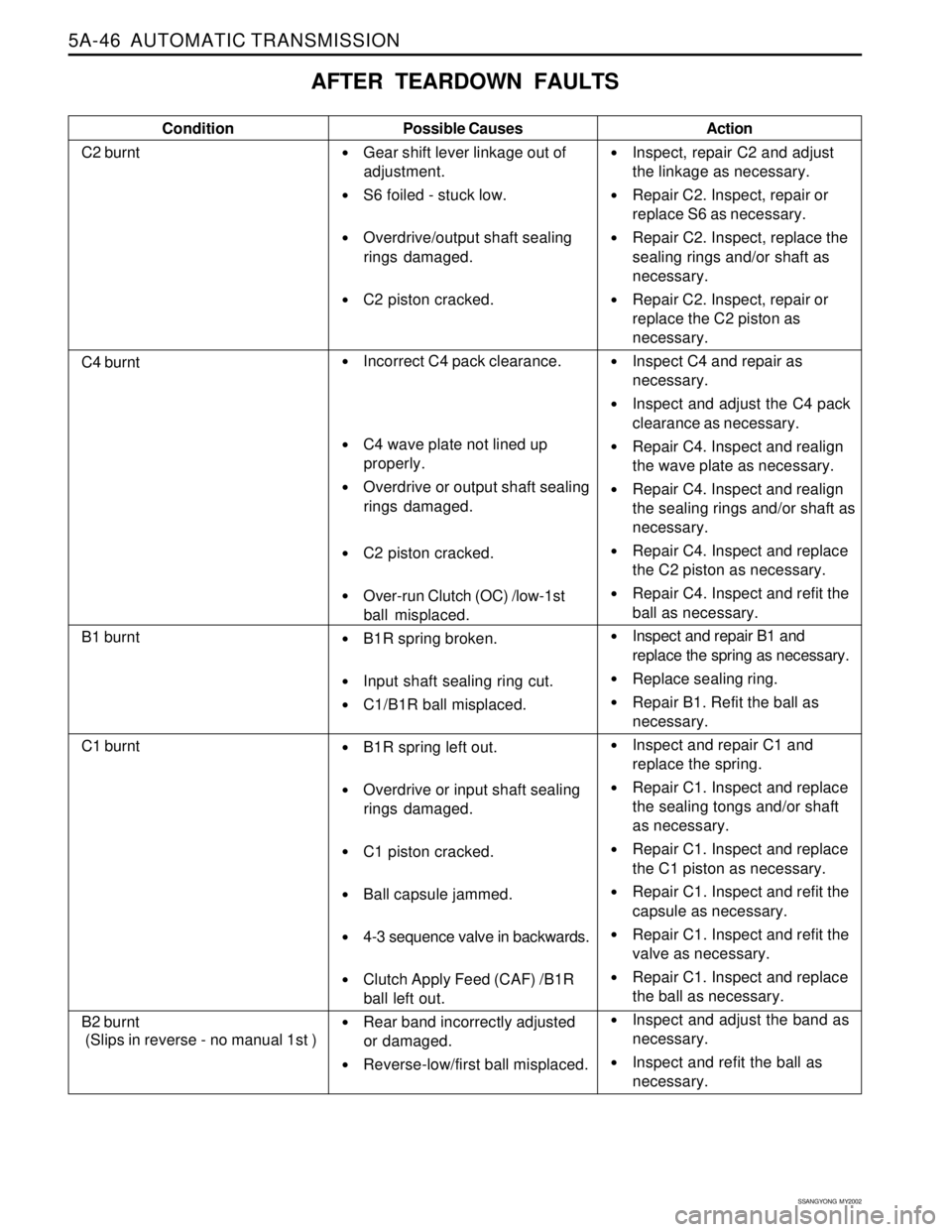
AFTER TEARDOWN FAULTS
Condition
C2 burntPossible Causes
Gear shift lever linkage out of
adjustment.
S6 foiled - stuck low.
Overdrive/output shaft sealing
rings damaged.
C2 piston cracked.
Incorrect C4 pack clearance.
C4 wave plate not lined up
properly.
Overdrive or output shaft sealing
rings damaged.
C2 piston cracked.
Over-run Clutch (OC) /low-1st
ball misplaced.
B1R spring broken.
Input shaft sealing ring cut.
C1/B1R ball misplaced.
B1R spring left out.
Overdrive or input shaft sealing
rings damaged.
C1 piston cracked.
Ball capsule jammed.
4-3 sequence valve in backwards.
Clutch Apply Feed (CAF) /B1R
ball left out.
Rear band incorrectly adjusted
or damaged.
Reverse-low/first ball misplaced.Action
Inspect, repair C2 and adjust
the linkage as necessary.
Repair C2. Inspect, repair or
replace S6 as necessary.
Repair C2. Inspect, replace the
sealing rings and/or shaft as
necessary.
Repair C2. Inspect, repair or
replace the C2 piston as
necessary.
Inspect C4 and repair as
necessary.
Inspect and adjust the C4 pack
clearance as necessary.
Repair C4. Inspect and realign
the wave plate as necessary.
Repair C4. Inspect and realign
the sealing rings and/or shaft as
necessary.
Repair C4. Inspect and replace
the C2 piston as necessary.
Repair C4. Inspect and refit the
ball as necessary.
Inspect and repair B1 and
replace the spring as necessary.
Replace sealing ring.
Repair B1. Refit the ball as
necessary.
Inspect and repair C1 and
replace the spring.
Repair C1. Inspect and replace
the sealing tongs and/or shaft
as necessary.
Repair C1. Inspect and replace
the C1 piston as necessary.
Repair C1. Inspect and refit the
capsule as necessary.
Repair C1. Inspect and refit the
valve as necessary.
Repair C1. Inspect and replace
the ball as necessary.
Inspect and adjust the band as
necessary.
Inspect and refit the ball as
necessary.
C4 burnt
B1 burnt
C1 burnt
B2 burnt
(Slips in reverse - no manual 1st )