1997 SSANGYONG KORANDO seat memory
[x] Cancel search: seat memoryPage 1097 of 2053

AUTOMATIC TRANSMISSION 5A-3
SSANGYONG MY2002
N - Neutral allows the engine to be started and oper-
ated while driving the vehicle. The inhibitor switch
allows the engine to be started. There is no power
transferred through the transmission in Neutral. But
the final drive is not locked by the parking pawl, so
thewheels are free to rotate.
D - Overdrive range is used for all normal driving
conditions. 4th gear (overdrive gear) reduces the
fuel consumption and the engine noise. Engine
braking is applied with reduced throttle.
First to second (1 → 2), first to third (1 → 3), second
to third (2 → 3), second to fourth (2 → 4), third to
fourth (3 → 4), fourth to third (4 → 3), fourth to
second (4 → 2), third to second (3 → 2), third to
first (3 → 1) and second to first (2 → 1) shifts are
all available as a function of vehicle speed, throttle
position and the time change rate of the throttle
position.
Downshifts are available for safe passing by
depress-ing the accelerator. Lockup clutch may be
enabled in 3rd and 4th gears depending on vehicle
type.
3 - Manual 3 provides three gear ratios (first through
third) and prevents the transmission from operating
in 4th gear. 3rd gear is used when driving on long
hill roads or in heavy city traffic. Downshifts are
available by depressing the accelerator.
2 - Manual 2 provides two gear ratios (first and
second). It is used to provide more power when
climbing hills or engine braking when driving down
a steep hill or starting off on slippery roads.
1 - Manual 1 is used to provide the maximum engine
braking when driving down the severe gradients.When NORMAL mode is selected upshifts will occur
to maximize fuel economy. When POWER mode is se-
lected, upshifts will occur to give maximum
performance and the POWER mode indicator light is
switched ON.
When WINTER mode is selected, starting in second
gear is facilitated, the WINTER mode indicator light is
switched ON and the POWER mode indicator light is
switched OFF.
Indicator Light
The indicator light is located on the instrument panel.
Auto shift indicator light comes ON when the ignition
switch ON and shows the gear shift control lever
position.
POWER mode indicator light comes ON when the
POWER mode is selected and when the kickdown
switch is depressed.
WINTER mode indicator light comes ON when the
WINTER mode is selected.
CONTROL SYSTEMS
BTRA M74 4WD automatic transmission consists of
two control systems. One is the electronic control
system that monitors vehicle parameters and adjusts
the transmission performance. Another is the hydraulic
control system that implements the commands of the
electronic control system commands.
ELECTRONIC CONTROL SYSTEM
The electronic control system comprises of sensors, a
TCM and seven solenoids. The TCM reads the inputs
and activates the outputs according to values stored
in Read Only Memory (ROM).
The TCM controls the hydraulic control system. This
control is via the hydraulic valve body, which contains
seven electromagnetic solenoids. Six of the seven
solenoids are used to control the line pressure, operate
the shift valves and the torque converter lock-up clutch,
and to turn ON and OFF the two regulator valves that
control the shift feel.
The seventh solenoid is the proportional or Variable
Pressure Solenoid (VPS) which works with the two regu-
lator valves to control shift feel.
Transmission Control Module (TCM)
The TCM is an in-vehicle micro-processor based trans-
mission management system. It is mounted under the
driver’s side front seat in the vehicle cabin.
The TCM contains:
Processing logic circuits which include a central mi-
croprocessor controller and a back-up memory
system.
Input circuits.
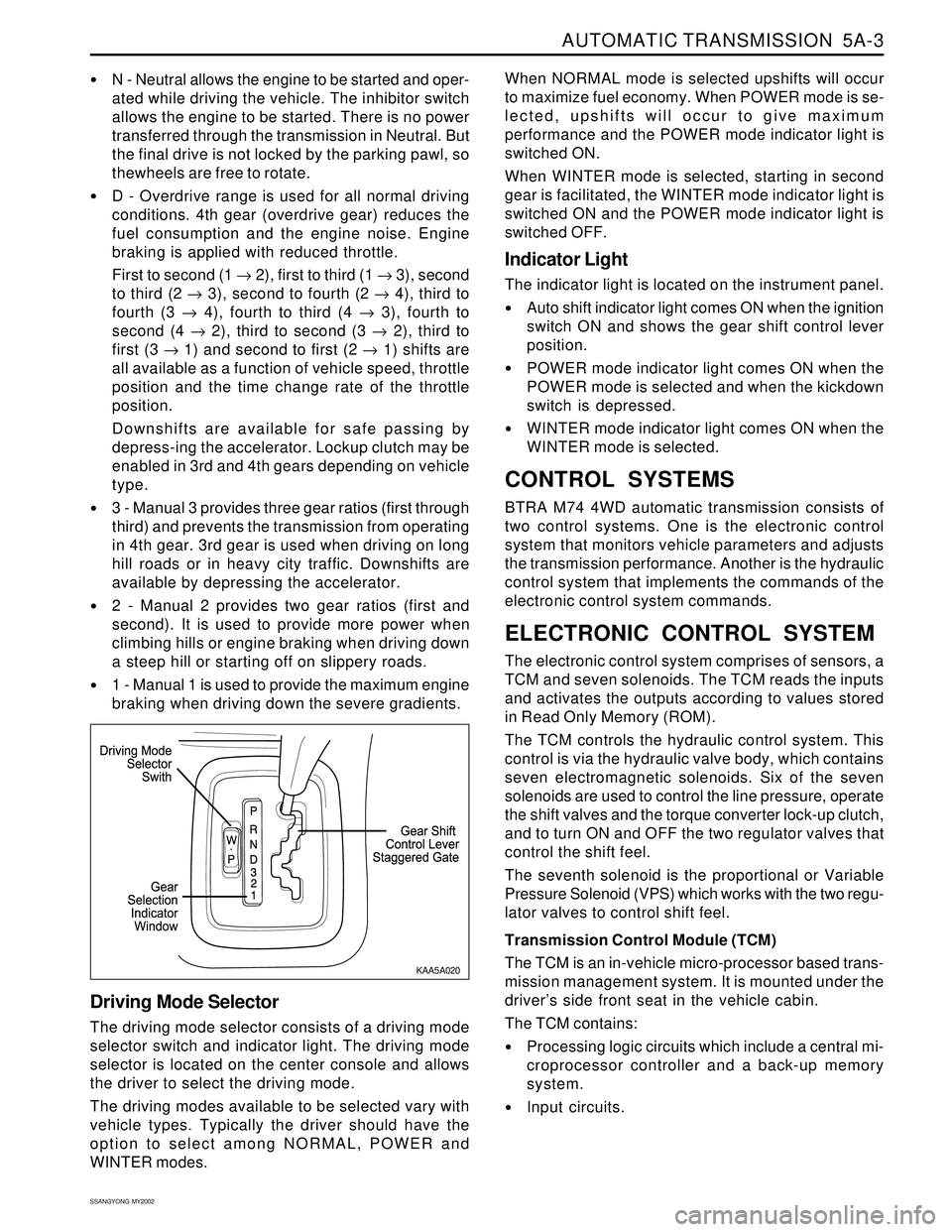
Driving Mode Selector
The driving mode selector consists of a driving mode
selector switch and indicator light. The driving mode
selector is located on the center console and allows
the driver to select the driving mode.
The driving modes available to be selected vary with
vehicle types. Typically the driver should have the
option to select among NORMAL, POWER and
WINTER modes.
KAA5A020
Page 1592 of 2053

SUPPLEMENTAL RESTRAINTS SYSTEM 8B-7
SSANGYONG MY2002
Driver Deployment Loop Shorted to Voltage
Passenger Deployment Loop Shorted to Voltage
Driver Seat Belt Pretensioner Shorted to Voltage
Passenger Seat Belt Pretensioner Shorted to Voltage
Driver Deployment Loop Shorted to Ground
Passenger Deployment Loop Shorted to Ground
Driver Seat Belt Pretensioner Shorted to Ground
Passenger Seat Belt Pretensioner Shorted to Ground
Driver Energy Shutdown Switch Error
Passenger Energy Shutdown Switch Error
Driver Seat Belt Pretensioner Energy Shutdown Switch Error
Passenger Seat Belt Pretensioner Energy Shutdown
Switch Error
Driver Ignition Switch Fault Internal
Passenger Ignition Switch Fault Internal
Driver Seat Belt Pretensioner Ignition Switch Fault
Passenger Seat Belt Pretensioner Ignition Switch Fault 01
02
03
04
05
06
07
08
09
10
11
12
13
14
15
16
DIAGNOSTIC INFORMATION AND PROCEDURES
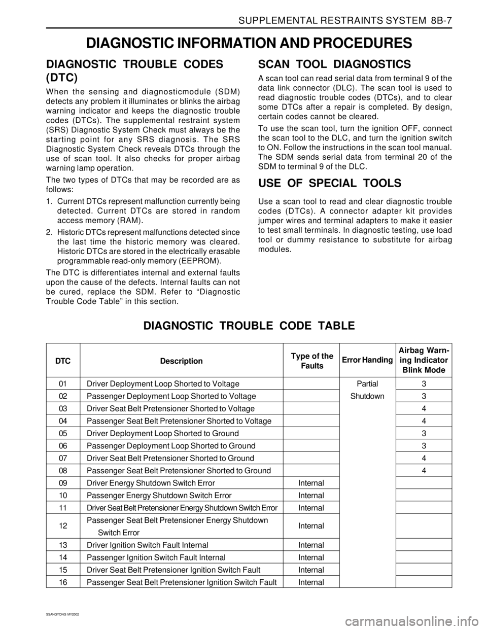
DIAGNOSTIC TROUBLE CODES
(DTC)
When the sensing and diagnosticmodule (SDM)
detects any problem it illuminates or blinks the airbag
warning indicator and keeps the diagnostic trouble
codes (DTCs). The supplemental restraint system
(SRS) Diagnostic System Check must always be the
starting point for any SRS diagnosis. The SRS
Diagnostic System Check reveals DTCs through the
use of scan tool. It also checks for proper airbag
warning lamp operation.
The two types of DTCs that may be recorded are as
follows:
1. Current DTCs represent malfunction currently being
detected. Current DTCs are stored in random
access memory (RAM).
2. Historic DTCs represent malfunctions detected since
the last time the historic memory was cleared.
Historic DTCs are stored in the electrically erasable
programmable read-only memory (EEPROM).
The DTC is differentiates internal and external faults
upon the cause of the defects. Internal faults can not
be cured, replace the SDM. Refer to “Diagnostic
Trouble Code Table” in this section.
SCAN TOOL DIAGNOSTICS
A scan tool can read serial data from terminal 9 of the
data link connector (DLC). The scan tool is used to
read diagnostic trouble codes (DTCs), and to clear
some DTCs after a repair is completed. By design,
certain codes cannot be cleared.
To use the scan tool, turn the ignition OFF, connect
the scan tool to the DLC, and turn the ignition switch
to ON. Follow the instructions in the scan tool manual.
The SDM sends serial data from terminal 20 of the
SDM to terminal 9 of the DLC.
USE OF SPECIAL TOOLS
Use a scan tool to read and clear diagnostic trouble
codes (DTCs). A connector adapter kit provides
jumper wires and terminal adapters to make it easier
to test small terminals. In diagnostic testing, use load
tool or dummy resistance to substitute for airbag
modules.
DIAGNOSTIC TROUBLE CODE TABLE
DTC DescriptionAirbag Warn-
ing Indicator
Blink Mode Error HandingType of the
Faults
Internal
Internal
Internal
Internal
Internal
Internal
Internal
Internal3
3
4
4
3
3
4
4
Partial
Shutdown