1997 SSANGYONG KORANDO stics
[x] Cancel search: sticsPage 925 of 2053

HYDRAULIC BRAKES 4A-5
SSANGYONG MY2002
Value(s)
-
-
-
-
-
-
-
-
-
-
-
-
-
-
BRAKE WARNING LAMP DIAGNOSIS
Step
1
2
3
4
5
6
7
8
9
10
11
12
13
14Action
Start the engine and leave it running.
Does the BRAKE warning lamp stay on?
With the engine running, release the parking brake.
Is the BRAKE warning lamp off?
Check the brake fluid level.
Is the fluid level OK?
1. Fill the brake fluid reservoir with clean DOT-3
hydraulic fluid.
2. Check the cap on the fluid reservoir.
3. Start the engine and leave it running.
Is the BRAKE warning lamp on?
Disconnect the wiring harness connector from the
brake fluid level switch.
Is the BRAKE warning lamp on?
Replace the brake fluid lever switch.
Is the repair complete?
1. Connect the brake fluid level switch.
2. Disconnect the parking brake lever switch.
3. Start the engine and leave it running.
Is the BRAKE warning lamp on?
Replace the parking brake lever switch.
Is the repair complete?
1. Connect the parking brake lever switch.
2. Disconnect the STICS (Super Time and Alarm
Integrated System).
3. Start the engine and leave it running.
Is the BRAKE warning lamp on?
Replace the STICS.
Is the repair complete?
Repair the short circuit in the instrument wiring
harness between terminal D10 of the instrument
cluster and ground.
Is the repair complete?
1. Disconnect the electrical connector from the fluid
level switch.
2. Connect a jumper wire between ground and
terminal 1 of the fluid level switch harness
connector.
Does the BRAKE warning lamp turn on?
1. Disconnect the electrical connector from the fluid
level switch.
2. Connect a jump wire between terminals 1 and 2
of the fluid level switch harness connector.
Does the BRAKE warning lamp turn on?
1. Replace the brake fluid level switch.
2 The switch can be removed and replaced without
draining the brake fluid from the reservoir.
Is the repair complete?Yes
Go To Step 2
System OK
Go To Step 5
Go To Step 5
Go To Step 7
System OK
Go To Step 9
System OK
Go To Step 11
System OK
System OK
Go To Step 13
Go To Step 14
System OKNO
Go To Step 12
Go To Step 3
Go To Step 4
System OK
Go To Step 6
-
Go To Step 8
-
Go To Step 10
-
-
Go To Step 15
Go To Step 15
-
Page 926 of 2053

SSAMGYONG MY2002
4A-6 HYDRAULIC BRAKES
Action
1. Turn the ignition ON.
2. Apply the parking brake.
Does the BRAKE warning lamp turn on?
Check fuse F30.
Is fuse F30 blown?
Check for a short circuit and repair it, if necessary.
Replace fuse F30.
1. Turn the ignition ON.
2. Check the voltage at F30.
Is the voltage equal to the specified value?
Repair the power supply to fuse F30.
Is the repair complete?
1. Disconnect terminal A1 of the instrument cluster.
2. Turn the ignition ON.
3. Use a voltmeter to check the voltage at terminal A1.
Is the voltage equal to the specified value?
Repair the open circuit between terminal A1 of the
instrument cluster and fuse F30.
Is the repair complete?
1. Reconnect terminal A1 of the instrument cluster.
Turn the ignition ON.
2. Use a voltmeter to backprobe terminal D10 of the
instrument cluster.
Is the voltage equal to the specified value?
1. Remove the BRAKE warning lamp from its socket.
2. Test the Brake warning lamp.
Is the BRAKEwarning lamp OK?
Replace the instrument cluster.
Is the repair complete?
Replace the BRAKE warning lamp.
Is the repair complete?
1. Disconnect terminal C10 of the STICS.
2. Connect a jumper wire between terminal C10 and
ground.
3. Turn the ignition ON.
Is the BRAKE warning lamp on?
Replace the STICS.
Is the repair complete?
1. Disconnect the STICS connector.
2. Connect a jump wire between terminal C19 and
ground.
3. Turn the ignition ON.
Is the BRAKE warning lamp on?
Replace the brake warning lamp switch.
Is the repair complete?
Repair the open circuit between the brake warning
lamp switch and terminal C19 of the STICS
BRAKE LAMP WARNING CIRCUIT (Cont’d)
Yes
Go To Step 31
Go To Step 17
System OK
Go To Step 20
System OK
Go To Step 22
System OK
Go To Step 26
Go To Step 24
System OK
System OK
Go To Step 27
System OK
Go To Step 29
System OK
System OKNO
Go To Step 16
Go To Step 18
-
Go To Step 19
-
Go To Step 21
-
Go To Step 23
Go To Step 25
-
-
Go To Step 28
-
Go To Step 30
-
-Step
15
16
17
18
19
20
21
22
23
24
25
26
27
28
29
30Value
-
-
-
11 - 14 v
-
11 - 14 v
-
11 - 14 v
-
-
-
-
-
-
-
-
Page 985 of 2053

SECTION 4F
ANTILOCK BRAKE SYSTEM AND
TRACTION CONTROL SYSTEM
TABLE OF CONTENTS
General Description and System Opertion..........4F-3
Basic Knowledge Required...................................4F-3
ABS System Components...................................4F-3
Traction Control System (TCS) Description...........4F-3
EBD System........................................................4F-5
EBD Failure Matrix...............................................4F-6
Tires and ABS/TCS..............................................4F-7
Hydraulic Circuit...................................................4F-8
ABS 5.3...............................................................4F-8
ABS/TCS 5.3.....................................................4F-11
Component Locator...........................................4F-14
ABS, ABS/TCS 5.3............................................4F-14
Diagnosis............................................................4F-15
Diagnostic Circuit Check....................................4F-15
ABS Indicator Lamp Inoperative.........................4F-18
Traction Control System (TCS) Indicator Lamp
Inoperative.....................................................4F-22
EBD Indicator Lamp Inoperative.........................4F-26
Power Supply to Control Module,
No DTCs Stored..............................................4F-30
ABS Indicator Lamp Illuminated Continuously,
No DTCs Stored..............................................4F-34
Self-Diagnostics................................................4F-36
Displaying DTCs................................................4F-36
Clearing DTCs...................................................4F-36
Intermittents and Poor Connections....................4F-36
DTC 03 - Left Front Wheel Speed Sensor Fault ...4F-38
DTC 07 - Left Front Wheel Speed Sensor
Continuity Fault...............................................4F-40
DTC 04 - Right Front Wheel Speed Sensor
Fault...............................................................4F-42DTC 08 - Right Front Wheel Speed Sensor
Continuity Fault...............................................4F-44
DTC 05 - Left Rear Wheel Speed Sensor Fault....4F-46
DTC 09 - Left Rear Wheel Speed Sensor
Continuity Fault...............................................4F-48
DTC 06 - Right Rear Wheel Speed Sensor Fault .4F-50
DTC 10 - Right Rear Wheel Speed Sensor
Continuity Fault...............................................4F-52
DTC 11 - Wheel Speed Sensor Frequency Error ..4F-54
DTC 42 - Acceleration Sensor Fault....................4F-58
DTC 43 - Acceleration Sensor Continuity Fault.....4F-60
DTC 13/14 - Left Front Inlet and Outlet Valve
Solenoid Fault.................................................4F-62
DTC 15/16 - Right Front Inlet and Outlet Valve
Solenoid Fault.................................................4F-64
DTC 17/18 - Left Rear Inlet and Outlet Valve
Solenoid Fault.................................................4F-66
DTC 19/20 - Right Rear Inlet and Outlet Valve
Solenoid Fault.................................................4F-68
DTC 21/22 - Left Rear Prime Line and Traction
Control System (TCS) Pilot Valve Fault............4F-70
DTC 23/24 - Right Rear Prime Line and Traction
Control System (TCS) Pilot Valve Fault............4F-72
DTC 12 - Valve Relay Circuit Fault......................4F-74
DTC 24 - Pump Motor or Pump Motor
Relay Fault.....................................................4E-76
DTC 27 - Stoplamp Switch Fault.........................4E-80
DTC 28 - Low Voltage Fault................................4E-84
DTC 02 - ABS Control Module Internal Fault........4E-88
Scheatic and Routing Diagrams........................4E-90
ABS Circuit (Without TCS): Gasoline...................4E-90
ABS/TCS Circuit: Gasoline.................................4E-91
ABS/ABD (Automatic Brake
Differential Lock): Diesel.................................4E-93
Page 1019 of 2053

SSANGYONG MY2002
4F-36 ABS AND TCS
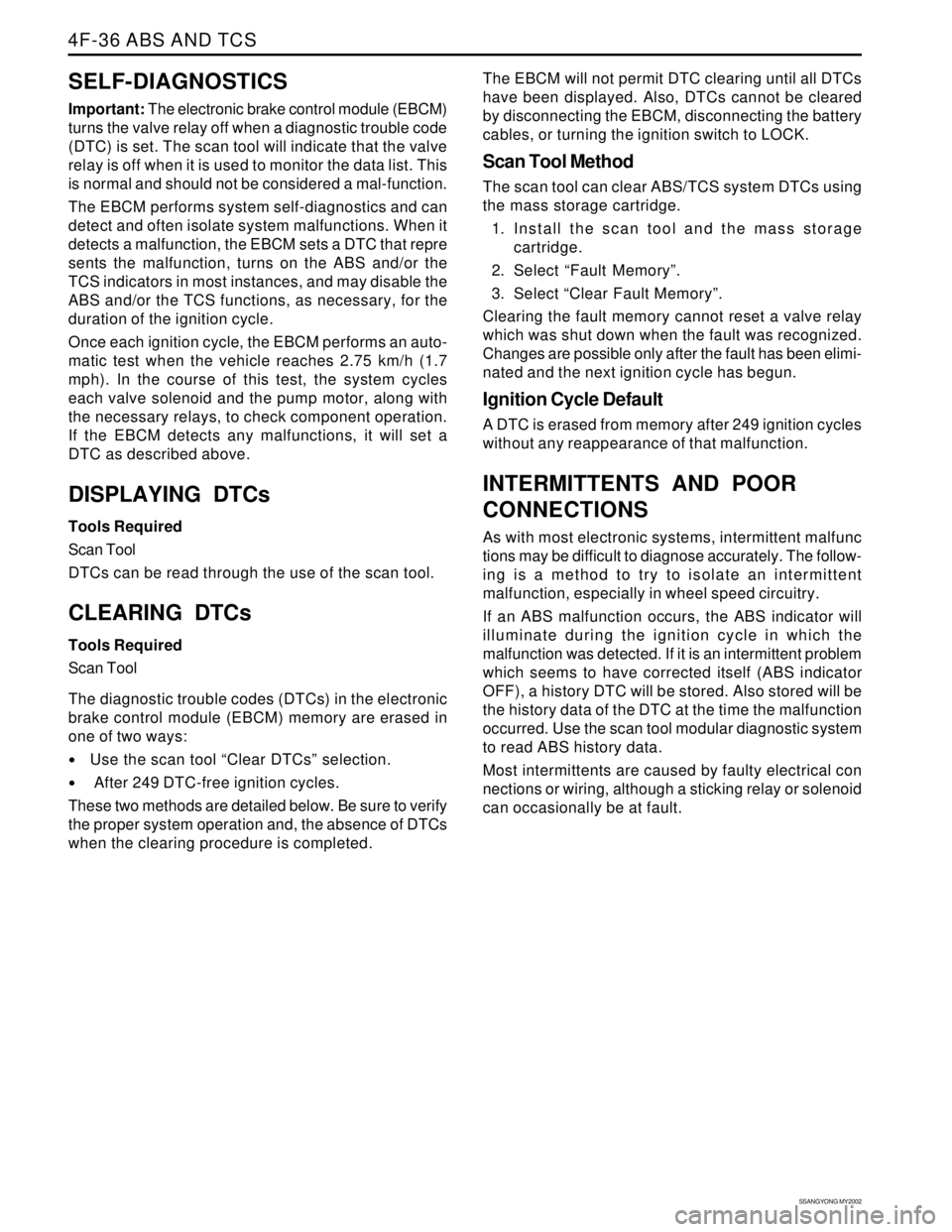
SELF-DIAGNOSTICS
Important: The electronic brake control module (EBCM)
turns the valve relay off when a diagnostic trouble code
(DTC) is set. The scan tool will indicate that the valve
relay is off when it is used to monitor the data list. This
is normal and should not be considered a mal-function.
The EBCM performs system self-diagnostics and can
detect and often isolate system malfunctions. When it
detects a malfunction, the EBCM sets a DTC that repre
sents the malfunction, turns on the ABS and/or the
TCS indicators in most instances, and may disable the
ABS and/or the TCS functions, as necessary, for the
duration of the ignition cycle.
Once each ignition cycle, the EBCM performs an auto-
matic test when the vehicle reaches 2.75 km/h (1.7
mph). In the course of this test, the system cycles
each valve solenoid and the pump motor, along with
the necessary relays, to check component operation.
If the EBCM detects any malfunctions, it will set a
DTC as described above.
DISPLAYING DTCs
Tools Required
Scan Tool
DTCs can be read through the use of the scan tool.
CLEARING DTCs
Tools Required
Scan Tool
The diagnostic trouble codes (DTCs) in the electronic
brake control module (EBCM) memory are erased in
one of two ways:
Use the scan tool “Clear DTCs” selection.
After 249 DTC-free ignition cycles.
These two methods are detailed below. Be sure to verify
the proper system operation and, the absence of DTCs
when the clearing procedure is completed.The EBCM will not permit DTC clearing until all DTCs
have been displayed. Also, DTCs cannot be cleared
by disconnecting the EBCM, disconnecting the battery
cables, or turning the ignition switch to LOCK.
Scan Tool Method
The scan tool can clear ABS/TCS system DTCs using
the mass storage cartridge.
1. Install the scan tool and the mass storage
cartridge.
2. Select “Fault Memory”.
3. Select “Clear Fault Memory”.
Clearing the fault memory cannot reset a valve relay
which was shut down when the fault was recognized.
Changes are possible only after the fault has been elimi-
nated and the next ignition cycle has begun.
Ignition Cycle Default
A DTC is erased from memory after 249 ignition cycles
without any reappearance of that malfunction.
INTERMITTENTS AND POOR
CONNECTIONS
As with most electronic systems, intermittent malfunc
tions may be difficult to diagnose accurately. The follow-
ing is a method to try to isolate an intermittent
malfunction, especially in wheel speed circuitry.
If an ABS malfunction occurs, the ABS indicator will
illuminate during the ignition cycle in which the
malfunction was detected. If it is an intermittent problem
which seems to have corrected itself (ABS indicator
OFF), a history DTC will be stored. Also stored will be
the history data of the DTC at the time the malfunction
occurred. Use the scan tool modular diagnostic system
to read ABS history data.
Most intermittents are caused by faulty electrical con
nections or wiring, although a sticking relay or solenoid
can occasionally be at fault.
Page 1098 of 2053

5A-4 AUTOMATIC TRANSMISSION
SSANGYONG MY2002
Output circuits which control external devices such
as the Variable Pressure Solenoid (VPS) driver, On/
Off solenoid drivers, a diagnostics output and the
driving mode indicator light.
Processing Logic
Shift schedule and calibration information is stored in
an Erasable Programmable Read Only Memory (EPROM).
Throttle input calibration constants and the diagnostics
information are stored in Electrically Erasable Program-
mable Read Only Memory (EEPROM) that retains the
memory even when power to the TCM is disconnected.
TCM continuously monitors the input values and uses
these, via the shift schedule, to determine the required
gear state. At the same time it monitors, via the solenoid
outputs, the current gear state, whenever the input
conditions change such that the required gear state is
different to the current gear state, the TCM initiates a
gear shift to bring the two states back into line.
Once the TCM has determined the type of gearshift
required the TCM accesses the shift logic, estimates
the engine torque output, adjusts the variable pressure
solenoid ramp pressure then executes the shift.The TCM continuously monitors every input and output
circuit for short or open circuits and operating range.
When a failure or abnormal operation is detected the
TCM records the condition code in the diagnostics
memory and implements a Limp Home Mode (LHM).
The actual limp home mode used depends upon the
failure detected with the object to maintain maximum
drive-ability without damaging the transmission. In
general input failures are handled by providing a default
value. Output failures, which are capable of damaging
the transmission, result in full limp mode giving only
third or fourth gear and reverse. For further details of
limp modes and memory retention refer to the
Diagnostic Trouble Code Diagnosis Section.
The TCM is designed to operate at ambient
temperatures between - 40 and 85 °C (- 40 and 185 °F).
It is also protected against electrical noise and voltage
spikes, however all the usual precautions should be
observed, for example when arc welding or jump
starting.
TCM Inputs
To function correctly, the TCM requires engine speed,
vehicle speed, transmission fluid temperature, throttle
position, gear position and Kickdown Switch inputs to
determine the variable pressure solenoid current ramp
and on/off solenoid states.
KAA5A030
This ensures the correct gear selection and shift feel
for all driving conditions.
The inputs required by the TCM are as follows;
Page 1144 of 2053

AUTOMATIC TRANSMISSION 5A-49
SSANGYONG MY2002
DIAGNOSTIC TROUBLE CODES (Cont'd)
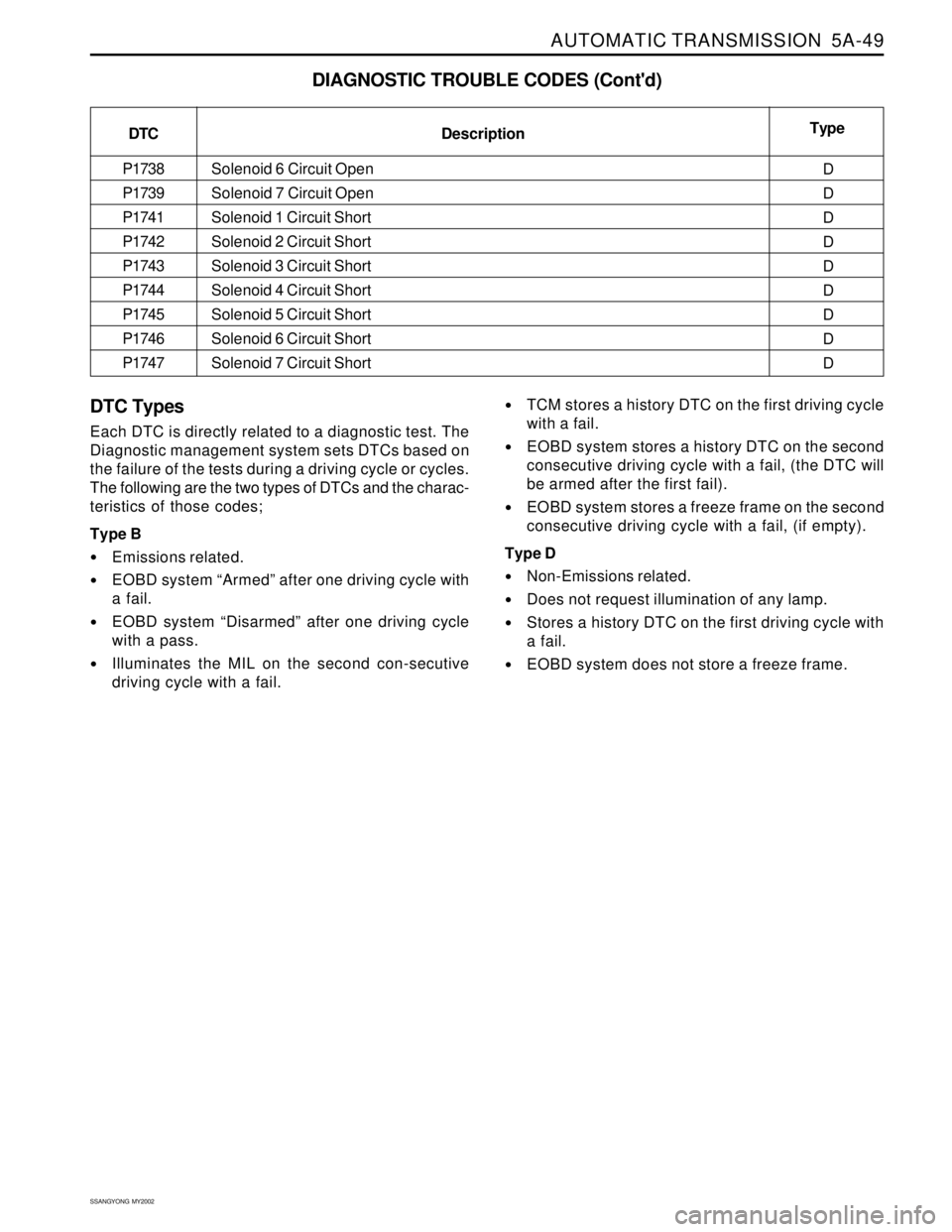
DTC Types
Each DTC is directly related to a diagnostic test. The
Diagnostic management system sets DTCs based on
the failure of the tests during a driving cycle or cycles.
The following are the two types of DTCs and the charac-
teristics of those codes;
Type B
Emissions related.
EOBD system “Armed” after one driving cycle with
a fail.
EOBD system “Disarmed” after one driving cycle
with a pass.
Illuminates the MIL on the second con-secutive
driving cycle with a fail.
TCM stores a history DTC on the first driving cycle
with a fail.
EOBD system stores a history DTC on the second
consecutive driving cycle with a fail, (the DTC will
be armed after the first fail).
EOBD system stores a freeze frame on the second
consecutive driving cycle with a fail, (if empty).
Type D
Non-Emissions related.
Does not request illumination of any lamp.
Stores a history DTC on the first driving cycle with
a fail.
EOBD system does not store a freeze frame. DTC
P1738
P1739
P1741
P1742
P1743
P1744
P1745
P1746
P1747
Type
D
D
D
D
D
D
D
D
D Description
Solenoid 6 Circuit Open
Solenoid 7 Circuit Open
Solenoid 1 Circuit Short
Solenoid 2 Circuit Short
Solenoid 3 Circuit Short
Solenoid 4 Circuit Short
Solenoid 5 Circuit Short
Solenoid 6 Circuit Short
Solenoid 7 Circuit Short
Page 1183 of 2053

5A-88 AUTOMATIC TRANSMISSION
SSANGYONG MY2002
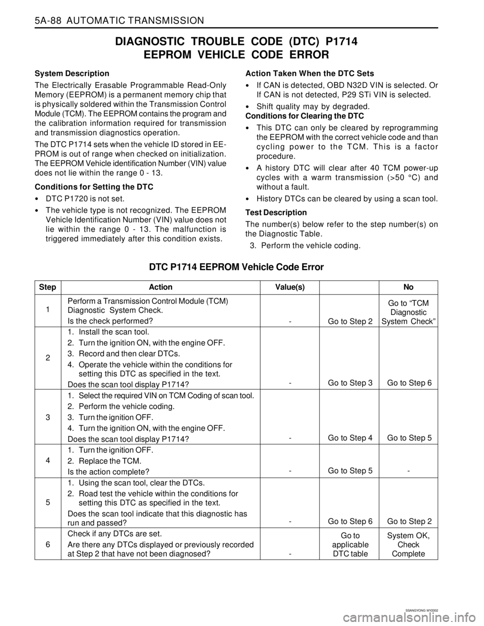
System Description
The Electrically Erasable Programmable Read-Only
Memory (EEPROM) is a permanent memory chip that
is physically soldered within the Transmission Control
Module (TCM). The EEPROM contains the program and
the calibration information required for transmission
and transmission diagnostics operation.
The DTC P1714 sets when the vehicle ID stored in EE-
PROM is out of range when checked on initialization.
The EEPROM Vehicle identification Number (VIN) value
does not lie within the range 0 - 13.
Conditions for Setting the DTC
DTC P1720 is not set.
The vehicle type is not recognized. The EEPROM
Vehicle Identification Number (VIN) value does not
lie within the range 0 - 13. The malfunction is
triggered immediately after this condition exists.
DIAGNOSTIC TROUBLE CODE (DTC) P1714
EEPROM VEHICLE CODE ERROR
Action Taken When the DTC Sets
If CAN is detected, OBD N32D VIN is selected. Or
If CAN is not detected, P29 STi VIN is selected.
Shift quality may by degraded.
Conditions for Clearing the DTC
This DTC can only be cleared by reprogramming
the EEPROM with the correct vehicle code and than
cycling power to the TCM. This is a factor
procedure.
A history DTC will clear after 40 TCM power-up
cycles with a warm transmission (>50 °C) and
without a fault.
History DTCs can be cleared by using a scan tool.
Test Description
The number(s) below refer to the step number(s) on
the Diagnostic Table.
3. Perform the vehicle coding.
DTC P1714 EEPROM Vehicle Code Error
1Perform a Transmission Control Module (TCM)
Diagnostic System Check.
Is the check performed?
1. Install the scan tool.
2. Turn the ignition ON, with the engine OFF.
3. Record and then clear DTCs.
4. Operate the vehicle within the conditions for
setting this DTC as specified in the text.
Does the scan tool display P1714?
1. Select the required VIN on TCM Coding of scan tool.
2. Perform the vehicle coding.
3. Turn the ignition OFF.
4. Turn the ignition ON, with the engine OFF.
Does the scan tool display P1714?
1. Turn the ignition OFF.
2. Replace the TCM.
Is the action complete?
1. Using the scan tool, clear the DTCs.
2. Road test the vehicle within the conditions for
setting this DTC as specified in the text.
Does the scan tool indicate that this diagnostic has
run and passed?
Check if any DTCs are set.
Are there any DTCs displayed or previously recorded
at Step 2 that have not been diagnosed?
StepAction Value(s) No
2
3
- Go to Step 5 - 4
- Go to Step 6 Go to Step 2 5
6
- Go to Step 2Go to “TCM
Diagnostic
System Check”
-Go to
applicable
DTC tableSystem OK,
Check
Complete
- Go to Step 3 Go to Step 6
- Go to Step 4 Go to Step 5
Page 1191 of 2053

5A-96 AUTOMATIC TRANSMISSION
SSANGYONG MY2002
DTC P1720 EEPROM Error
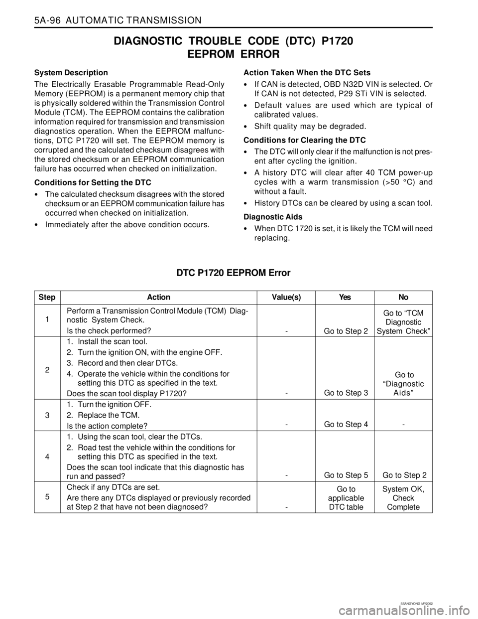
System Description
The Electrically Erasable Programmable Read-Only
Memory (EEPROM) is a permanent memory chip that
is physically soldered within the Transmission Control
Module (TCM). The EEPROM contains the calibration
information required for transmission and transmission
diagnostics operation. When the EEPROM malfunc-
tions, DTC P1720 will set. The EEPROM memory is
corrupted and the calculated checksum disagrees with
the stored checksum or an EEPROM communication
failure has occurred when checked on initialization.
Conditions for Setting the DTC
The calculated checksum disagrees with the stored
checksum or an EEPROM communication failure has
occurred when checked on initialization.
Immediately after the above condition occurs.
DIAGNOSTIC TROUBLE CODE (DTC) P1720
EEPROM ERROR
Action Taken When the DTC Sets
If CAN is detected, OBD N32D VIN is selected. Or
If CAN is not detected, P29 STi VIN is selected.
Default values are used which are typical of
calibrated values.
Shift quality may be degraded.
Conditions for Clearing the DTC
The DTC will only clear if the malfunction is not pres-
ent after cycling the ignition.
A history DTC will clear after 40 TCM power-up
cycles with a warm transmission (>50 °C) and
without a fault.
History DTCs can be cleared by using a scan tool.
Diagnostic Aids
When DTC 1720 is set, it is likely the TCM will need
replacing.
1Perform a Transmission Control Module (TCM) Diag-
nostic System Check.
Is the check performed?
1. Install the scan tool.
2. Turn the ignition ON, with the engine OFF.
3. Record and then clear DTCs.
4. Operate the vehicle within the conditions for
setting this DTC as specified in the text.
Does the scan tool display P1720?
1. Turn the ignition OFF.
2. Replace the TCM.
Is the action complete?
1. Using the scan tool, clear the DTCs.
2. Road test the vehicle within the conditions for
setting this DTC as specified in the text.
Does the scan tool indicate that this diagnostic has
run and passed?
Check if any DTCs are set.
Are there any DTCs displayed or previously recorded
at Step 2 that have not been diagnosed?
StepAction Value(s) Yes No
2
3
- Go to Step 4 -
4
- Go to Step 5 Go to Step 2
5
- Go to Step 2Go to “TCM
Diagnostic
System Check”
- Go to Step 3 Go to
“Diagnostic
Aids”
-Go to
applicable
DTC tableSystem OK,
Check
Complete