1997 SSANGYONG KORANDO stics
[x] Cancel search: sticsPage 1195 of 2053
5A-100 AUTOMATIC TRANSMISSION
SSANGYONG MY2002
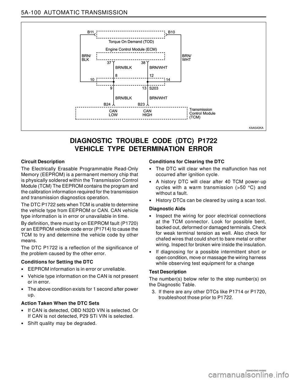
Circuit Description
The Electrically Erasable Programmable Read-Only
Memory (EEPROM) is a permanent memory chip that
is physically soldered within the Transmission Control
Module (TCM) The EEPROM contains the program and
the calibration information required for the transmission
and transmission diagnostics operation.
The DTC P1722 sets when TCM is unable to determine
the vehicle type from EEPROM or CAN. CAN vehicle
type information is in error or unavailable in time.
By definition, there must by on EEPROM fault (P1720)
or an EEPROM vehicle code error (P1714) to cause the
TCM to try and determine the vehicle code by other
means.
The DTC P1722 is a reflection of the significance of
the problem caused by the other error.
Conditions for Setting the DTC
EEPROM information is in error or unreliable.
Vehicle type information on the CAN is not present
or in error.
The above condition exists for 1 second after power
up.
Action Taken When the DTC Sets
If CAN is detected, OBD N32D VIN is selected. Or
If CAN is not detected, P29 STi VIN is selected.
Shift quality may be degraded.
DIAGNOSTIC TROUBLE CODE (DTC) P1722
VEHICLE TYPE DETERMINATION ERROR
Conditions for Clearing the DTC
The DTC will clear when the malfunction has not
occurred after ignition cycle.
A history DTC will clear after 40 TCM power-up
cycles with a warm transmission (>50 °C) and
without a fault.
History DTCs can be cleared by using a scan tool.
Diagnostic Aids
Inspect the wiring for poor electrical connections
at the TCM connector. Look for possible bent,
backed out, deformed or damaged terminals. Check
for weak terminal tension as well. Also check for
chafed wires that could short to bare metal or other
wiring. Inspect for broken wire inside the insulation.
If diagnosing for a possible intermittent short or
open condition, move or massage the wiring harness
while observing test equipment for a change
Test Description
The number(s) below refer to the step number(s) on
the Diagnostic Table.
3. If there are any other DTCs like P1714 or P1720,
troubleshoot those prior to P1722.
KAA5A3KA
Page 1372 of 2053
SECTION 5D1
TRANSFER CASE (TOD)
CAUTION: Disconnect the negative battery cable before removing or installing any electrical unit or when a
tool or equipment could easily come in contact with exposed electrical terminals. Disconnecting this cable
will help prevent personal injury and damage to the vehicle. The ignition must also be in LOCK unless
other-wise noted.
TABLE OF CONTENTS
Description and Operation.................................5D1-2
Torque on Demand (TOD) System
Transfer Case.................................................5D1-2
Transfer Case Control Unit (TCCU).....................5D1-2
TCCU Coding....................................................5D1-2
Pin Description..................................................5D1-3
Components of the TOD Transfer Case System ..5D1-4
Definition of Terminology....................................5D1-4
Operation of the TOD Transfer Case System......5D1-4
Component Locator...........................................5D1-7
Torque on Demand (TOD) Type Transfer Case....5D1-7
Transfer Case Disassembled View.....................5D1-8
TOD Control Unit..............................................5D1-10
Diagnosis..........................................................5D1-11
Self-Diagnostic Tests.......................................5D1-11
Diagnostic Trouble Codes (DTCs)....................5D1-12
Clearing Diagnostic Trouble Codes..................5D1-12
4WD Check Indicator Stays on with Ignition
Switch ON....................................................5D1-14
4WD Low Indicator Stays on with Ignition
Switch ON....................................................5D1-16
No 4WD Check or 4WD Low Indicator with
Ignition Switch ON........................................5D1-18
4WD Low Indicator Blink Steadily.....................5D1-20
TCCU Diagnostic System Check......................5D1-21
DTC 1714 Eeprom Checksum Fault..................5D1-22
DTC 1715 Tp Sensor Loss of Signal.................5D1-24
DTC 1716 Tp Sensor Out of Range...................5D1-26
DTC 1721 Electromagnetic Clutch Open / Short
to Battery.....................................................5D1-28
DTC 1722 Electromagnetic Clutch Short to
Ground.........................................................5D1-32
DTC 1731 Front Speed Sensor Voltage Low......5D1-36
DTC 1732 Front Speed Sensor Voltage High.....5D1-38DTC 1733 Rear Speed Sensor Voltage Low......5D1-40
DTC 1734 Rear Speed Sensor Voltage High.....5D1-42
DTC 1735 Speed Sensor Reference Voltage
Low ..............................................................5D1-44
DTC 1736 Speed Sensor Reference Voltage
High.............................................................5D1-46
DTC 1741 Motor Output Open / Shorted
to Battery.....................................................5D1-48
DTC 1742 Motor Output Shorted to Ground......5D1-52
DTC 1743 Shift System Timeout.......................5D1-55
DTC 1750 General Position Encoder Fault
(Invalid Code)...............................................5D1-56
DTC 1751 Position 1 Shorted to Ground............5D1-58
DTC 1752 Position 2 Shorted to Ground............5D1-60
DTC 1753 Position 3 Shorted to Ground............5D1-62
DTC 1754 Position 4 Shorted to Ground............5D1-64
Repair Instructions............................................5D1-66
On-Vehicle Service.............................................5D1-66
Oil Replacement..............................................5D1-66
Transfer Case Control Unit (TCCU)...................5D1-67
Transfer Case..................................................5D1-67
Shift Motor.......................................................5D1-69
Front and Rear Propeller Shaft Speed Sensor ...5D1-70
Unit Repair........................................................5D1-71
Transfer Case Overhaul...................................5D1-71
Specifications...................................................5D1-79
General Specification.......................................5D1-79
TCCU Electric Characteristics..........................5D1-79
Fastener Tightening Specifications...................5D1-79
Schematic and Routing Diagram....................5D1-80
TOD Transfer Case Control Unit (TCCU)............5D1-80
Special Tools and Equipment..........................5D1-82
Special Tool Table ...........................................5D1-82
Page 1586 of 2053
SECTION 8B
SUPPLEMENTAL RESTRAINTS SYSTEM
CAUTION: Disconnect the negative battery cable before removing or installing any electrical unit or when a
tool or equipment could easily come in contact with exposed electrical terminals. Disconnecting this cable
will help prevent personal injury and damage to the vehicle. The ignition must also be in LOCK unless
other-wise noted.
TABLE OF CONTENTS
Description and Operation...................................8B-3
Supplemental Restraint System (SRS)..................8B-3
Airbag Modules...................................................8B-3
Front Seat Belt Pretensioners...............................8B-4
Sensing and Diagnostic Module (SDM)................8B-4
Airbag Warning Lamp ..........................................8B-5
Clock Spring........................................................8B-5
Wiring Harness Connectors..................................8B-5
Components Locator............................................8B-6
SRS Component and Wiring Location View...........8B-6
Diagnostic Information and Procedures..............8B-7
Diagnostic Trouble Codes (DTC)..........................8B-7
Scan Tool Diagnostics.........................................8B-7
Use of Special Tools............................................8B-7
Diagnostic Trouble Code Table............................8B-7
SRS Diagnostic System Check..........................8B-10
Sensing and Diagnostic Module (SDM)
Integrity Check...............................................8B-12
Airbag Warning Lamp Stays on with Ignition
Switch ON......................................................8B-14
DTCs - Internal Fault..........................................8B-16
DTCs 01 Driver Deployment Loop Shorted to
Voltage...........................................................8B-18
DTC 02 Passenger Deployment Loop Shorted to
Voltage...........................................................8B-20
DTC 03 Driver Seat Belt Pretensioner Shorted to
Voltage...........................................................8B-22
DTC 04 Passenger Seat Belt Pretensioner
Shorted to Voltage..........................................8B-24
DTC 05 Driver Deployment Loop Shorted to
Ground...........................................................8B-26
DTC 06 Passenger Deployment Loop Shorted to
Ground...........................................................8B-28
DTC 07 Driver Seat Belt Pretensioner Shorted to
Ground...........................................................8B-30DTC 08 Passenger Seat Belt Pretensioner
Shorted to Ground ..........................................8B-32
DTC 17 Driver Deployment Loop
Resistance High.............................................8B-34
DTC 18 Passenger Deployment Loop
Resistance High.............................................8B-38
DTC 19 Driver Seat Belt Pretensioner
Deployment Loop resistance High...................8B-40
DTC 20 Passenger Seat Belt Pretensioner
Deployment Loop Resistance High.................8B-42
DTC 21 Driver Airbag Deployment Loop
Resistance Low..............................................8B-44
DTC 22 Passenger Airbag Deployment Loop
Resistance Low..............................................8B-48
DTC 23 Driver Seat Belt Pretensioner
Deployment Loop resistance Low....................8B-50
DTC 24 Passenger Seat Belt Pretensioner
Deployment Loop Resistance Low..................8B-52
DTC 46 Airbag Warning Lamp Circuit Open or
Short to Ground/Battery..................................8B-54
DTC 47 Battery Voltage is Out of
Specification...................................................8B-56
Repair Instruction...............................................8B-58
On-Vehicle Service...............................................8B-58
Service Precaution.............................................8B-58
Disabling the Supplemental Restraint
System (SRS).................................................8B-58
Enabling the Supplemental Restraint
System (SRS).................................................8B-58
Handling, Installation and Diagnosis..................8B-58
Repairs and Inspections Required After an
Accident ........................................................8B-58
Accident with Deployment - Components
Replacement..................................................8B-58
Accident without Deployment - Component
Inspection......................................................8B-59
Page 1592 of 2053
SUPPLEMENTAL RESTRAINTS SYSTEM 8B-7
SSANGYONG MY2002
Driver Deployment Loop Shorted to Voltage
Passenger Deployment Loop Shorted to Voltage
Driver Seat Belt Pretensioner Shorted to Voltage
Passenger Seat Belt Pretensioner Shorted to Voltage
Driver Deployment Loop Shorted to Ground
Passenger Deployment Loop Shorted to Ground
Driver Seat Belt Pretensioner Shorted to Ground
Passenger Seat Belt Pretensioner Shorted to Ground
Driver Energy Shutdown Switch Error
Passenger Energy Shutdown Switch Error
Driver Seat Belt Pretensioner Energy Shutdown Switch Error
Passenger Seat Belt Pretensioner Energy Shutdown
Switch Error
Driver Ignition Switch Fault Internal
Passenger Ignition Switch Fault Internal
Driver Seat Belt Pretensioner Ignition Switch Fault
Passenger Seat Belt Pretensioner Ignition Switch Fault 01
02
03
04
05
06
07
08
09
10
11
12
13
14
15
16
DIAGNOSTIC INFORMATION AND PROCEDURES
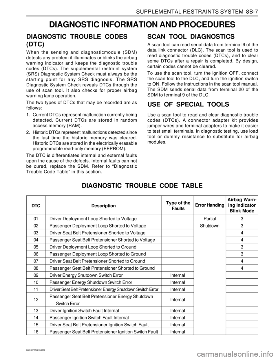
DIAGNOSTIC TROUBLE CODES
(DTC)
When the sensing and diagnosticmodule (SDM)
detects any problem it illuminates or blinks the airbag
warning indicator and keeps the diagnostic trouble
codes (DTCs). The supplemental restraint system
(SRS) Diagnostic System Check must always be the
starting point for any SRS diagnosis. The SRS
Diagnostic System Check reveals DTCs through the
use of scan tool. It also checks for proper airbag
warning lamp operation.
The two types of DTCs that may be recorded are as
follows:
1. Current DTCs represent malfunction currently being
detected. Current DTCs are stored in random
access memory (RAM).
2. Historic DTCs represent malfunctions detected since
the last time the historic memory was cleared.
Historic DTCs are stored in the electrically erasable
programmable read-only memory (EEPROM).
The DTC is differentiates internal and external faults
upon the cause of the defects. Internal faults can not
be cured, replace the SDM. Refer to “Diagnostic
Trouble Code Table” in this section.
SCAN TOOL DIAGNOSTICS
A scan tool can read serial data from terminal 9 of the
data link connector (DLC). The scan tool is used to
read diagnostic trouble codes (DTCs), and to clear
some DTCs after a repair is completed. By design,
certain codes cannot be cleared.
To use the scan tool, turn the ignition OFF, connect
the scan tool to the DLC, and turn the ignition switch
to ON. Follow the instructions in the scan tool manual.
The SDM sends serial data from terminal 20 of the
SDM to terminal 9 of the DLC.
USE OF SPECIAL TOOLS
Use a scan tool to read and clear diagnostic trouble
codes (DTCs). A connector adapter kit provides
jumper wires and terminal adapters to make it easier
to test small terminals. In diagnostic testing, use load
tool or dummy resistance to substitute for airbag
modules.
DIAGNOSTIC TROUBLE CODE TABLE
DTC DescriptionAirbag Warn-
ing Indicator
Blink Mode Error HandingType of the
Faults
Internal
Internal
Internal
Internal
Internal
Internal
Internal
Internal3
3
4
4
3
3
4
4
Partial
Shutdown
Page 1640 of 2053
SSANGYONG MY2002
8B-58 SUPPLEMENTAL RESTRAINTS SYSTEM
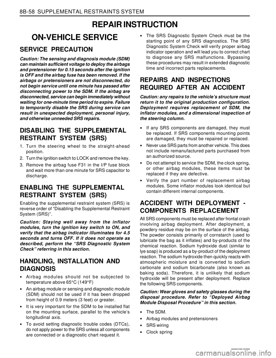
REPAIR INSTRUCTION
ON-VEHICLE SERVICE
SERVICE PRECAUTION
Caution: The sensing and diagnosis module (SDM)
can maintain sufficient voltage to deploy the airbags
and pretensioner for 0.15 seconds after the ignition
is OFF and the airbag fuse has been removed. If the
airbags or pretensioners are not disconnected, do
not begin service until one minute has passed after
disconnecting power to the SDM. If the airbag are
disconnected, service can begin immediately without
waiting for one-minute time period to expire. Failure
to temporarily disable the SRS during service can
result in unexpected deployment, personal injury,
and otherwise unneeded SRS repairs.
DISABLING THE SUPPLEMENTAL
RESTRAINT SYSTEM (SRS)
1. Turn the steering wheel to the straight-ahead
position.
2. Turn the ignition switch to LOCK and remove the key.
3. Remove the airbag fuse F31 in the I/P fuse block
and wait more than one minute for SRS capacitor to
discharge.
ENABLING THE SUPPLEMENTAL
RESTRAINT SYSTEM (SRS)
Enabling the supplemental restraint system (SRS) is
reverse order of “Disabling the Supplemental Restraint
System (SRS)”.
Caution: Staying well away from the inflator
modules, turn the ignition key switch to ON, and
verify that the airbag indicator illuminates for 4.5
seconds and turns OFF. If it does not operate as
described, perform the “SRS Diagnostic System
Check” referring in this section.
HANDLING, INSTALLATION AND
DIAGNOSIS
Airbag modules should not be subjected to
temperature above 65°C (149°F)
An airbag module or sensing and diagnostic module
(SDM) should not be used if it has been dropped
from height of 0.9 meters (3 feet) or greater.
It is very important for the SDM to be installed flat
on the mounting surface, parallel to the vehicle’s
longitudinal axis.
To avoid setting diagnostic trouble codes (DTCs),
do not apply power to the SRS unless all components
are connected or a diagnostic chart request it.
The SRS Diagnostic System Check must be the
starting point of any SRS diagnostics. The SRS
Diagnostic System Check will verify proper airbag
indicator operation and will lead you to correct chart
to diagnose any SRS malfunctions. Bypassing
these procedures may result in extended diagnostic
time and incorrect parts replacements.
REPAIRS AND INSPECTIONS
REQUIRED AFTER AN ACCIDENT
Caution: any repairs to the vehicle’s structure must
return it to the original production configuration.
Deployment requires replacement of SDM, the
inflator modules, and a dimensional inspection of
the steering column.
If any SRS components are damaged, they must
be replaced. If SRS components mounting points
are damaged, they must be repaired or replaced.
Never use SRS parts from another vehicle. This does
not include remanufactured parts purchased from
an authorized source.
Do not attempt to service the SDM, the clock spring,
or other airbag modules, these items must be
replaced if they are defective.
Verify the part number of replacement airbag
modules. Some inflator modules look identical but
contain different internal components.
ACCIDENT WITH DEPLOYMENT -
COMPONENTS REPLACEMENT
All SRS components must be replaced after frontal crash
involving airbag deployment. After deployment, a
powdery residue may be on the surface of the airbag.
The powder consists primarily of cornstarch (used to
lubricate the bag as it inflates) and by-products of the
chemical reaction. Sodium hydroxide dust (similar to
lye soap) is produced as a by-product of the deployment
reaction. The sodium hydroxide then quickly reacts with
atmospheric moisture and is converted to sodium
carbonate and sodium bicarbonate (also known as
baking soda). Therefore, it is unlikely that sodium
hydroxide will be present after deployment. Replace
the following SRS components.
Caution: Wear gloves and safety glasses during the
disposal procedure. Refer to “Deployed Airbag
Module Disposal Procedure” in this section.
The SDM.
Airbag modules and pretensioners
SRS wiring
Clock spring
Page 1658 of 2053
BODY WIRING SYSTEM 9A-7
SSANGYONG MY2002
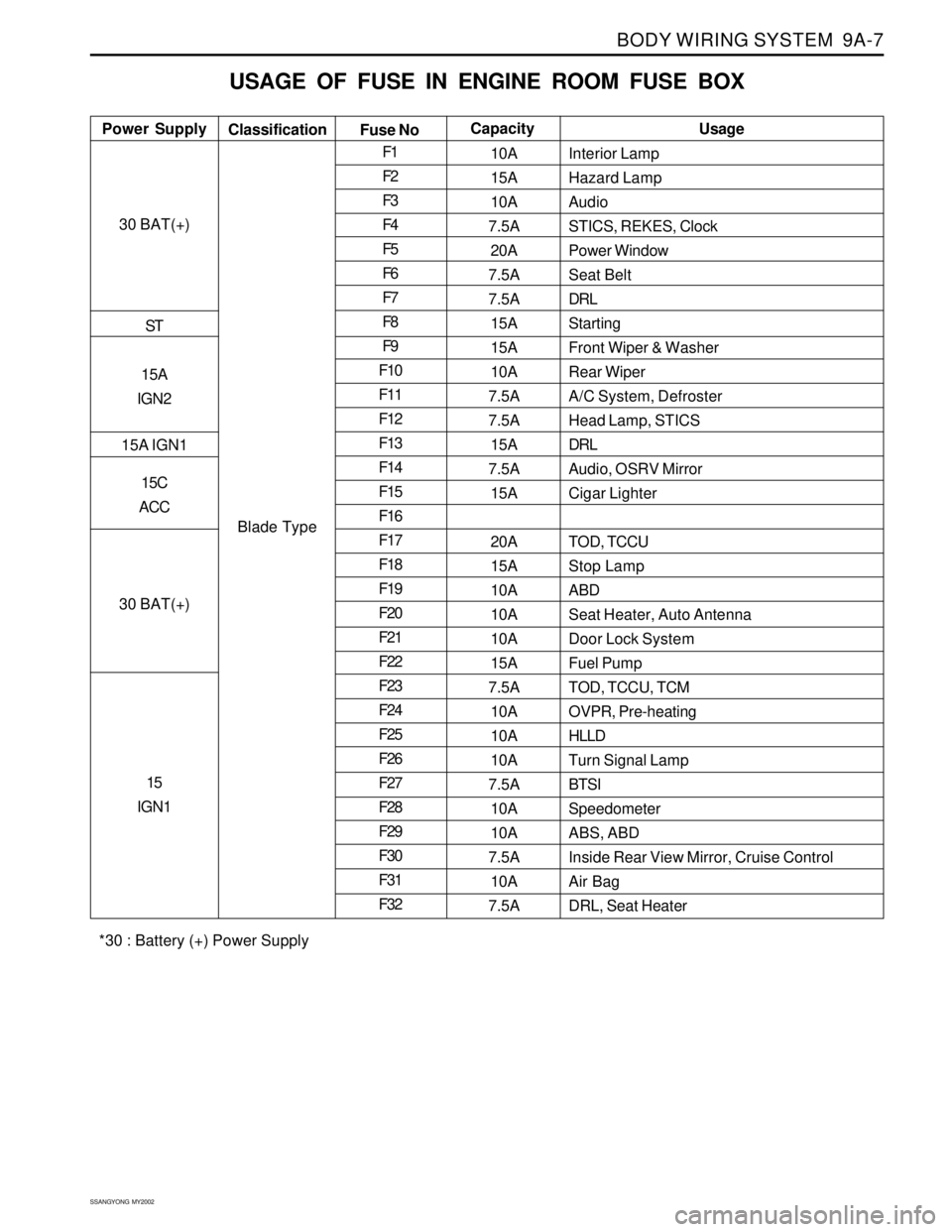
USAGE OF FUSE IN ENGINE ROOM FUSE BOX
Interior Lamp
Hazard Lamp
Audio
STICS, REKES, Clock
Power Window
Seat Belt
DRL
Starting
Front Wiper & Washer
Rear Wiper
A/C System, Defroster
Head Lamp, STICS
DRL
Audio, OSRV Mirror
Cigar Lighter
TOD, TCCU
Stop Lamp
ABD
Seat Heater, Auto Antenna
Door Lock System
Fuel Pump
TOD, TCCU, TCM
OVPR, Pre-heating
HLLD
Turn Signal Lamp
BTSI
Speedometer
ABS, ABD
Inside Rear View Mirror, Cruise Control
Air Bag
DRL, Seat Heater Power SupplyUsage
Classification
Fuse NoCapacity
30 BAT(+)
ST
15A
IGN2
15A IGN1
15C
ACC
30 BAT(+)
15
IGN1
Blade TypeF1
F2
F3
F4
F5
F6
F7
F8
F9
F10
F11
F12
F13
F14
F15
F16
F17
F18
F19
F20
F21
F22
F23
F24
F25
F26
F27
F28
F29
F30
F31
F3210A
15A
10A
7.5A
20A
7.5A
7.5A
15A
15A
10A
7.5A
7.5A
15A
7.5A
15A
20A
15A
10A
10A
10A
15A
7.5A
10A
10A
10A
7.5A
10A
10A
7.5A
10A
7.5A
*30 : Battery (+) Power Supply
Page 1664 of 2053
BODY WIRING SYSTEM 9A-13
SSANGYONG MY2002
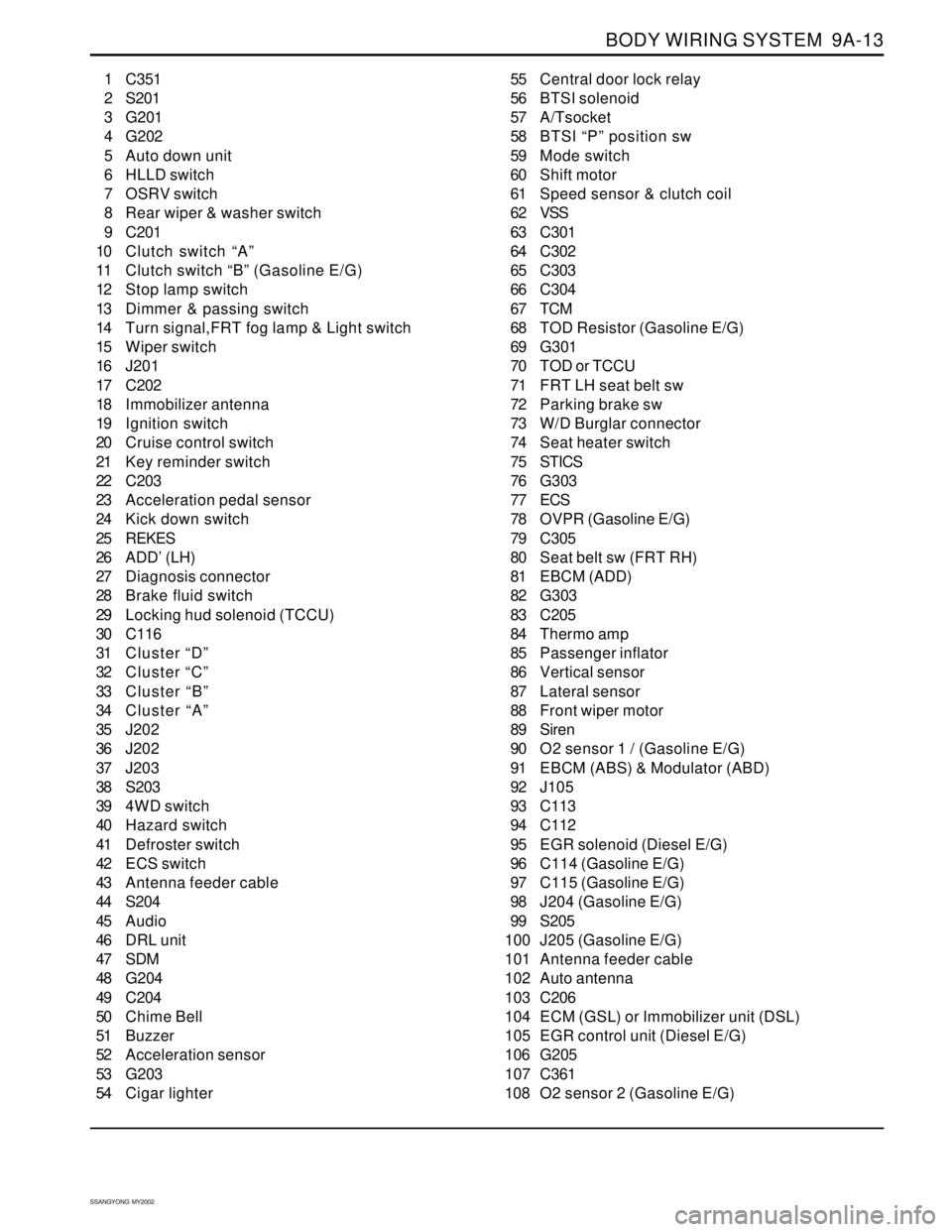
1 C351
2 S201
3 G201
4 G202
5 Auto down unit
6 HLLD switch
7 OSRV switch
8 Rear wiper & washer switch
9 C201
10 Clutch switch “A”
11 Clutch switch “B” (Gasoline E/G)
12 Stop lamp switch
13 Dimmer & passing switch
14 Turn signal,FRT fog lamp & Light switch
15 Wiper switch
16 J201
17 C202
18 Immobilizer antenna
19 Ignition switch
20 Cruise control switch
21 Key reminder switch
22 C203
23 Acceleration pedal sensor
24 Kick down switch
25 REKES
26 ADD’ (LH)
27 Diagnosis connector
28 Brake fluid switch
29 Locking hud solenoid (TCCU)
30 C116
31 Cluster “D”
32 Cluster “C”
33 Cluster “B”
34 Cluster “A”
35 J202
36 J202
37 J203
38 S203
39 4WD switch
40 Hazard switch
41 Defroster switch
42 ECS switch
43 Antenna feeder cable
44 S204
45 Audio
46 DRL unit
47 SDM
48 G204
49 C204
50 Chime Bell
51 Buzzer
52 Acceleration sensor
53 G203
54 Cigar lighter55 Central door lock relay
56 BTSI solenoid
57 A/Tsocket
58 BTSI “P” position sw
59 Mode switch
60 Shift motor
61 Speed sensor & clutch coil
62 VSS
63 C301
64 C302
65 C303
66 C304
67 TCM
68 TOD Resistor (Gasoline E/G)
69 G301
70 TOD or TCCU
71 FRT LH seat belt sw
72 Parking brake sw
73 W/D Burglar connector
74 Seat heater switch
75 STICS
76 G303
77 ECS
78 OVPR (Gasoline E/G)
79 C305
80 Seat belt sw (FRT RH)
81 EBCM (ADD)
82 G303
83 C205
84 Thermo amp
85 Passenger inflator
86 Vertical sensor
87 Lateral sensor
88 Front wiper motor
89 Siren
90 O2 sensor 1 / (Gasoline E/G)
91 EBCM (ABS) & Modulator (ABD)
92 J105
93 C113
94 C112
95 EGR solenoid (Diesel E/G)
96 C114 (Gasoline E/G)
97 C115 (Gasoline E/G)
98 J204 (Gasoline E/G)
99 S205
100 J205 (Gasoline E/G)
101 Antenna feeder cable
102 Auto antenna
103 C206
104 ECM (GSL) or Immobilizer unit (DSL)
105 EGR control unit (Diesel E/G)
106 G205
107 C361
108 O2 sensor 2 (Gasoline E/G)
Page 1848 of 2053
SECTION 9T1
REMOTE KEYLESS ENTRY AND ANTI-THEFT
SYSTEM
CAUTION: Disconnect the negative battery cable before removing or installing any electrical unit or when a
tool or equipment could easily come in contact with exposed electrical terminals. Disconnecting this cable
will help prevent personal injury and damage to the vehicle. The ignition must also be in LOCK unless
otherwise noted.
TABLE OF CONTENTS
Description and Operation.................................9T1-2
Remote Keyless Entry and Anti-Theft System.....9T1-2
Components Locator..........................................9T1-3
REKES & STICS................................................9T1-3
Diagnostic Information and Procedure.............9T1-4
Input Memory....................................................9T1-5
Repair Instructions..............................................9T1-6
On-Vehicle Service Unit Repair..............................9T1-6Receiver............................................................9T1-6
Antenna.............................................................9T1-6
Stics..................................................................9T1-6
Schematic and Routing Diagrams.....................9T1-7
STICS - Stics Unit..............................................9T1-7
STICS - Door Contact Switch..............................9T1-8
STICS - Keyless, Key Reminder Switch, Siren,
Chime Bell Buzzer ..........................................9T1-9