1997 SSANGYONG KORANDO low beam
[x] Cancel search: low beamPage 13 of 2053

GENERAL INFORMATION 0B -- 13
D AEW OO M Y_2000
OWNER INSPECTIONS AND SERVICES
WHILE OPERATING THE VEHICLE
Horn Operation
Blow the horn occasionally to make sure it works. Check
all the button locations.
Brake System Operation
Be alert for abnormal sounds, increased brake pedal
travel or repeated puling to one side when braking. Also,
if the brake warning light goes on, or flashes, something
may be wrong with part of the brake system.
Exhaust System Operation
Be alert to any changes inthe sound of the system or
the smell of the fumes. These are signs that the system
may be leaking or overheating. Have the system in-
spected and repaired immediately.
Tires, Wheels and Alignment Operation
Be alert to any vibration of the steering wheel or the
seats at normal highway speeds. This may mean a
wheel needs to be balanced. Also, a pull right or left on a
straight, level road may show the need for a tire pres-
sure adjustment or a wheel alignment.
Steering System Operation
Be alert to changes in the steering action. An inspection
is needed when the steering wheel is hard to turn or has
too much free play, or is unusual sounds are noticed
when turning or parking.
Headlight Aim
Take note of the light pattern occasionally. Adjust the
headlights if the beams seem improperly aimed.
AT EACH FUEL FILL
A fluid loss in any (except windshield washer) system
may indicate a problem. Have the system inspected and
repaired immediately.
Engine Oil Level
Check the oil level and add oil if necessary. The best
time to check the engine oil level is when the oil is warm.
1. After stopping the engine, wait a few minutes for the
oil to drain back to the oil pan.
2. Pull out the oil level indicator (dip stick).
3. Wipe it clean, and push the oil level indicator back
down all the way.
4. Pull out the oil level indicator and look at the oil level
on it.
5. Add oil, if needed, to keep the oil level above the low-
er mark. Avoid overfilling theengine, since this may
cause engine damage.
6. Push the indicator all the way back down into the en-
gine after taking the reading.If you check the oil level when the oil is cold, do not run
the engine first. The cold oil will not drain back to the pan
fast enough to give a true oil level reading.
Engine Coolant Level and Condition
Check the coolant level in the coolant reservoir tank and
add coolant if necessary. Inspect the coolant. Replace
dirty or rusty coolant.
Windshield Washer Fluid Level
Check the washer fluid level in the reservoir. Add fluid if
necessary.
AT LEAST TWICE A MONTH
Tire And Wheel Inspection and Pressure
Check
Check the tire for abnormal wear or damage. Also check
for damaged wheels. Check the tire pressure when the
tires are cold ( check the spare also, unless it is a stow-
away). Maintain the recommended pressures. Refer to
“Tire and Wheel” is in section 0B.
AT LEAST MONTHLY
Light Operation
Check the operation of the license plate light, the head-
lights (including the high beams), the parking lights, the
fog lights, the taillight, the brake lights, the turn signals,
the backup lights and the hazard warning flasher.
Fluid Leak Check
Periodically inspect the surface beneath the vehicle for
water, oil, fuel or other fluids, after the vehicle has been
parked for a while. Water dripping from the air condition-
ing system after use is normal. If you notice fuel leaks or
fumes, find the cause and correct it at once.
AT LEAST TWICE A YEAR
Power Steering System Reservoir Level
Check the power steering fluid level. Keep the power
steering fluid at the proper level. Refer to Section 6A,
Power Steering System.
Brake Master Cylinder Reservoir Level
Check the fluid and keep it at the proper level. A low fluid
level can indicate worn disc brake pads which may need
to be serviced. Check the breather hole in the reservoir
cover to be free from dirt and check for an open pas-
sage.
Weather- Strip Lubrication
Apply a thin film silicone grease using a clean cloth.
Page 1488 of 2053
SSANGYONG MY2002
6E-2 POWER STEERING AND COLUMN
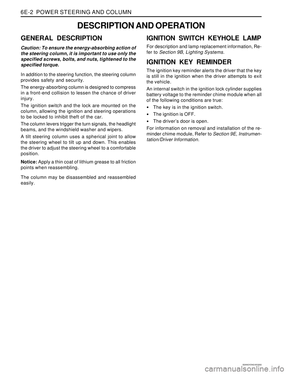
GENERAL DESCRIPTION
Caution: To ensure the energy-absorbing action of
the steering column, it is important to use only the
specified screws, bolts, and nuts, tightened to the
specified torque.
In addition to the steering function, the steering column
provides safety and security.
The energy-absorbing column is designed to compress
in a front-end collision to lessen the chance of driver
injury.
The ignition switch and the lock are mounted on the
column, allowing the ignition and steering operations
to be locked to inhibit theft of the car.
The column levers trigger the turn signals, the headlight
beams, and the windshield washer and wipers.
A tilt steering column uses a spherical joint to allow
the steering wheel to tilt up and down. This enables
the driver to adjust the steering wheel to a comfortable
position.
Notice: Apply a thin coat of lithium grease to all friction
points when reassembling.
The column may be disassembled and reassembled
easily.
DESCRIPTION AND OPERATION
IGNITION SWITCH KEYHOLE LAMP
For description and lamp replacement information, Re-
fer to Section 9B, Lighting Systems.
IGNITION KEY REMINDER
The ignition key reminder alerts the driver that the key
is still in the ignition when the driver attempts to exit
the vehicle.
An internal switch in the ignition lock cylinder supplies
battery voltage to the reminder chime module when all
of the following conditions are true:
•The key is in the ignition switch.
The ignition is OFF.
The driver’s door is open.
For information on removal and installation of the re-
minder chime module, Refer to Section 9E, Instrumen-
tation/Driver Information.
Page 1676 of 2053
SSANGYONG MY2002
9B-2 LIGHTING SYSTEM
DESCRIPTION AND OPERATION
HEAD LAMPS - ON REMINDER
When the headlamp switch is in the headlamps-on or
parkinglamps-on positions, voltage is applied to the
chime module. With the headlamp switch on and the
driver’s side door open, the module loses voltage. The
module senses this change. If voltage is still available,
it is applied to sound the chime. The chime can be
turned off by turning the headlamp switch off or closing
the driver’s side door. To replace the chime module,
refer to Section 9E, Instrumentation / Driver Information.
HEAD LAMPS
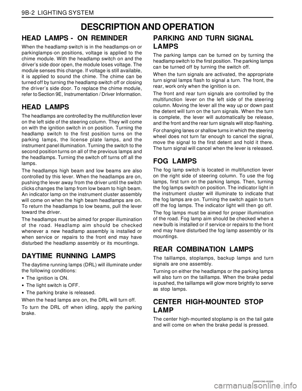
The headlamps are controlled by the multifunction lever
on the left side of the steering column. They will come
on with the ignition switch in on position. Turning the
headlamp switch to the first position turns on the
parking lamps, the license plate lamps, and the
instrument panel illumination. Turning the switch to the
second position turns on all of the previous lamps and
the headlamps. Turning the switch off turns off all the
lamps.
The headlamps high beam and low beams are also
controlled by this lever. When the headlamps are on,
pushing the lever away from the driver until the switch
clicks changes the lamp from low beam to high beam.
An indicator lamp on the instrument cluster assembly
will come on when the high beam headlamps are on.
To return the headlamps to low beams, pull the lever
toward the driver.
The headlamps must be aimed for proper illumination
of the road. Headlamp aim should be checked
whenever a new headlamp assembly is installed or
when service or repairs to the front end may have
disturbed the headlamp assembly or its mountings.
DAYTIME RUNNING LAMPS
The daytime running lamps (DRL) will illuminate under
the following conditions:
The ignition is ON.
The light switch is OFF.
The parking brake is released.
When the head lamps are on, the DRL will turn off.
To turn the DRL off when idling, apply the parking
brake.
PARKING AND TURN SIGNAL
LAMPS
The parking lamps can be turned on by turning the
headlamp switch to the first position. The parking lamps
can be turned off by turning the switch off.
When the turn signals are activated, the appropriate
turn signal lamps flash to signal a turn. The front, the
rear, work only when the ignition is on.
The front and rear turn signals are controlled by the
multifunction lever on the left side of the steering
column. Moving the lever all the way up or down past
the detent will turn on the turn signals. When the turn
is complete, the lever will automatically be release,
and the front and the rear turn signals will stop flashing.
For changing lanes or shallow turns in which the steering
wheel does not turn far enough to cancel the signal,
move the signal to the first detent and hold it there.
The turn signal will cancel when the lever is released.
FOG LAMPS
The fog lamp switch is located in multifunction lever
on the right side of steering column. To use the fog
lamps, first turn on the parking lamps. Then, turning
the fog lamps switch on position. The indicator light in
the instrument cluster will illuminate to indicate that
the fog lamps are on. Turning the switch again to turn
off the fog lamps. The indicator light will then go off.
The fog lamps must be aimed for proper illumination
of the road. Fog lamp aim should be checked when a
new bulb is installed or if service or repairs to the front
end may have disturbed the fog lamp assembly or its
mountings.
REAR COMBINATION LAMPS
The taillamps, stoplamps, backup lamps and turn
signals are one assembly.
Turning on either the headlamps or the parking lamps
will also turn on the taillamps. When the brake pedal
is pushed, the taillamps will glow more brightly to serve
as stop lamps.
CENTER HIGH-MOUNTED STOP
LAMP
The center high-mounted stoplamp is on the tail gate
and will come on when the brake pedal is pressed.
Page 1679 of 2053
LIGHTING SYSTEM 9B-5
SSANGYONG MY2002
DIAGNOSTIC INFORMATION AND PROCEDURE
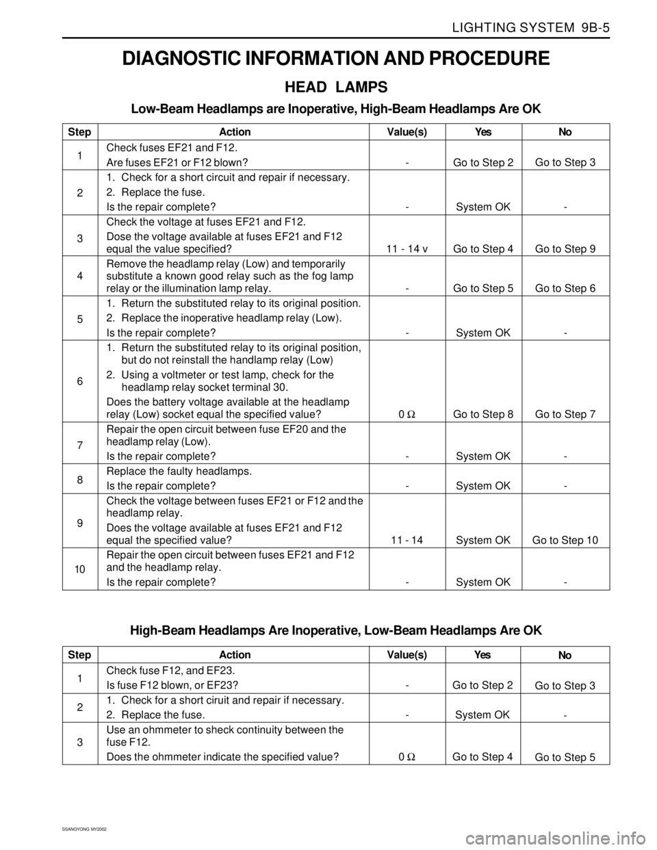
HEAD LAMPS
Low-Beam Headlamps are Inoperative, High-Beam Headlamps Are OK
Step
1
2
3
4
5
6
7
8
9
10Action
Check fuses EF21 and F12.
Are fuses EF21 or F12 blown?
1. Check for a short circuit and repair if necessary.
2. Replace the fuse.
Is the repair complete?
Check the voltage at fuses EF21 and F12.
Dose the voltage available at fuses EF21 and F12
equal the value specified?
Remove the headlamp relay (Low) and temporarily
substitute a known good relay such as the fog lamp
relay or the illumination lamp relay.
1. Return the substituted relay to its original position.
2. Replace the inoperative headlamp relay (Low).
Is the repair complete?
1. Return the substituted relay to its original position,
but do not reinstall the handlamp relay (Low)
2. Using a voltmeter or test lamp, check for the
headlamp relay socket terminal 30.
Does the battery voltage available at the headlamp
relay (Low) socket equal the specified value?
Repair the open circuit between fuse EF20 and the
headlamp relay (Low).
Is the repair complete?
Replace the faulty headlamps.
Is the repair complete?
Check the voltage between fuses EF21 or F12 and the
headlamp relay.
Does the voltage available at fuses EF21 and F12
equal the specified value?
Repair the open circuit between fuses EF21 and F12
and the headlamp relay.
Is the repair complete?Yes
Go to Step 2
System OK
Go to Step 4
Go to Step 5
System OK
Go to Step 8
System OK
System OK
System OK
System OKNo
Go to Step 3
-
Go to Step 9
Go to Step 6
-
Go to Step 7
-
-
Go to Step 10
- Value(s)
-
-
11 - 14 v
-
-
0 Ω
-
-
11 - 14
-
High-Beam Headlamps Are Inoperative, Low-Beam Headlamps Are OK
Step
1
2
3Action
Check fuse F12, and EF23.
Is fuse F12 blown, or EF23?
1. Check for a short ciruit and repair if necessary.
2. Replace the fuse.
Use an ohmmeter to sheck continuity between the
fuse F12.
Does the ohmmeter indicate the specified value?Yes
Go to Step 2
System OK
Go to Step 4No
Go to Step 3
-
Go to Step 5 Value(s)
-
-
0 Ω
Page 1680 of 2053
SSANGYONG MY2002
9B-6 LIGHTING SYSTEM
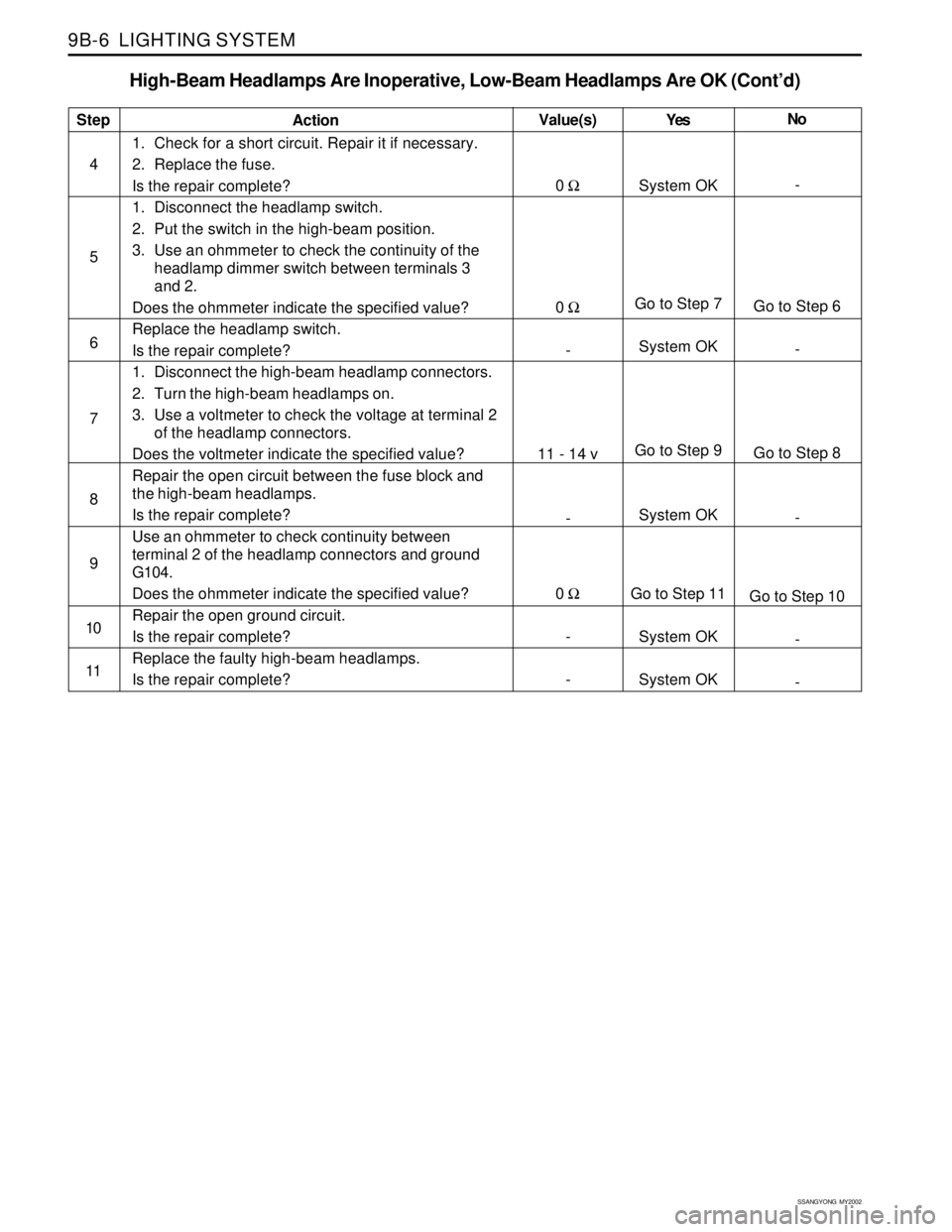
High-Beam Headlamps Are Inoperative, Low-Beam Headlamps Are OK (Cont’d)
Step
4
5
6
7
8
9
10
11Action
1. Check for a short circuit. Repair it if necessary.
2. Replace the fuse.
Is the repair complete?
1. Disconnect the headlamp switch.
2. Put the switch in the high-beam position.
3. Use an ohmmeter to check the continuity of the
headlamp dimmer switch between terminals 3
and 2.
Does the ohmmeter indicate the specified value?
Replace the headlamp switch.
Is the repair complete?
1. Disconnect the high-beam headlamp connectors.
2. Turn the high-beam headlamps on.
3. Use a voltmeter to check the voltage at terminal 2
of the headlamp connectors.
Does the voltmeter indicate the specified value?
Repair the open circuit between the fuse block and
the high-beam headlamps.
Is the repair complete?
Use an ohmmeter to check continuity between
terminal 2 of the headlamp connectors and ground
G104.
Does the ohmmeter indicate the specified value?
Repair the open ground circuit.
Is the repair complete?
Replace the faulty high-beam headlamps.
Is the repair complete?Yes
System OK
Go to Step 7
System OK
Go to Step 9
System OK
Go to Step 11
System OK
System OKNo
-
Go to Step 6
-
Go to Step 8
-
Go to Step 10
-
- Value(s)
0 Ω
0 Ω
-
11 - 14 v
-
0 Ω
-
-
Page 1898 of 2053
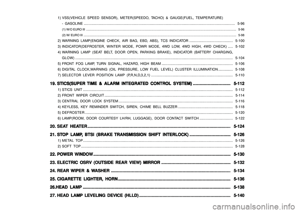
1) VSS(VEHICLE SPEED SENSOR), METER(SPEEDO, TACHO) & GAUGE(FUEL, TEMPERATURE)
- GASOLINE ........................................................................................................................................................... 5-96
(1) W/O EURO III .................................................................................................................................................................................... 5-96
(2) W/ EURO III ....................................................................................................................................................................................... 5-98
2) WARNING LAMP(ENGINE CHECK, AIR BAG, EBD, ABS), TCS INDICATOR............................................. 5-100
3) INDICATOR(DEFROSTER, WINTER MODE, POWR MODE, 4WD LOW, 4WD HIGH, 4WD CHECK)..... 5-102
4) WARNING LAMP (SEAT BELT, DOOR OPEN, PARKING BRAKE), INDICATOR (BATTERY CHARGING,
GLOW).................................................................................................................................................................. 5-104
5) FRONT FOG LAMP, TURN SIGNAL, HAZARD, HIGH BEAM ......................................................................... 5-106
6) DIGITAL CLOCK,WARNING (OIL PRESSURE, LOW FUEL LEVEL) CLUSTER ILLUMINATION............... 5-108
7) SELECTOR LEVER POSITION LAMP (P,R,N,D,3,2,1).................................................................................... 5-110
19. 19.19. 19.
19.
STICS(SUPER STICS(SUPER STICS(SUPER STICS(SUPER
STICS(SUPER
TIME & ALARM INTEGRA TIME & ALARM INTEGRATIME & ALARM INTEGRA TIME & ALARM INTEGRA
TIME & ALARM INTEGRA
TED CONTR TED CONTRTED CONTR TED CONTR
TED CONTR
OL SYSTEM) OL SYSTEM)OL SYSTEM) OL SYSTEM)
OL SYSTEM)
................................ ................................................................ ................................
................................
5-112 5-112 5-112 5-112
5-112
1) STICS UNIT .......................................................................................................................................................... 5-112
2) FRONT WIPER CIRCUIT.................................................................................................................................... 5-114
3) CENTRAL DOOR LOCK SYSTEM ..................................................................................................................... 5-116
4) KEYLESS, KEY REMINDER SWITCH, SIREN, CHIME BELL BUZZER ........................................................ 5-118
5) DEFROSTER........................................................................................................................................................ 5-120
6) LAMP(ROOM, DOOR COURTESY LH/RH, LUGGAGE), DOOR CONTACT SWITCH .................................. 5-122
20. 20.20. 20.
20.
SEA SEASEA SEA
SEA
T HEA T HEAT HEA T HEA
T HEA
TER TERTER TER
TER
.......................................................................................................................... .................................................................................................................................................................................................................................................... ..........................................................................................................................
..........................................................................................................................
5-124 5-124 5-124 5-124
5-124
21. 21.21. 21.
21.
ST STST ST
ST
OP LAMP OP LAMPOP LAMP OP LAMP
OP LAMP
, ,, ,
,
BTSI (BRAKE BTSI (BRAKE BTSI (BRAKE BTSI (BRAKE
BTSI (BRAKE
TRANSMISSION SHIFT INTERLOCK) TRANSMISSION SHIFT INTERLOCK)TRANSMISSION SHIFT INTERLOCK) TRANSMISSION SHIFT INTERLOCK)
TRANSMISSION SHIFT INTERLOCK)
................................... ...................................................................... ...................................
...................................
5-126 5-126 5-126 5-126
5-126
1) METAL TOP .......................................................................................................................................................... 5-126
2) SOFT TOP............................................................................................................................................................ 5-128
22. 22.22. 22.
22.
POWER WINDOW POWER WINDOWPOWER WINDOW POWER WINDOW
POWER WINDOW
..................................................................................................................... .......................................................................................................................................................................................................................................... .....................................................................................................................
.....................................................................................................................
5-130 5-130 5-130 5-130
5-130
23. 23.23. 23.
23.
ELECTRIC OSRV (OUTSIDE REAR VIEW) MIRROR ELECTRIC OSRV (OUTSIDE REAR VIEW) MIRRORELECTRIC OSRV (OUTSIDE REAR VIEW) MIRROR ELECTRIC OSRV (OUTSIDE REAR VIEW) MIRROR
ELECTRIC OSRV (OUTSIDE REAR VIEW) MIRROR
........................................................... ...................................................................................................................... ...........................................................
...........................................................
5-132 5-132 5-132 5-132
5-132
24. 24.24. 24.
24.
REAR REAR REAR REAR
REAR
WIPER & WIPER & WIPER & WIPER &
WIPER &
W WW W
W
ASHER ASHERASHER ASHER
ASHER
...................................................................................................... ............................................................................................................................................................................................................ ......................................................................................................
......................................................................................................
5-134 5-134 5-134 5-134
5-134
25. 25.25. 25.
25.
CIGARETTE LIGHTER, HORN CIGARETTE LIGHTER, HORNCIGARETTE LIGHTER, HORN CIGARETTE LIGHTER, HORN
CIGARETTE LIGHTER, HORN
................................................................................................ ................................................................................................................................................................................................ ................................................................................................
................................................................................................
5-136 5-136 5-136 5-136
5-136
26.HEAD LAMP 26.HEAD LAMP26.HEAD LAMP 26.HEAD LAMP
26.HEAD LAMP
.............................................................................................................................. ............................................................................................................................................................................................................................................................ ..............................................................................................................................
..............................................................................................................................
5-138 5-138 5-138 5-138
5-138
27. 27.27. 27.
27.
HEAD LAMP LEVELING DEVICE (HLLD) HEAD LAMP LEVELING DEVICE (HLLD)HEAD LAMP LEVELING DEVICE (HLLD) HEAD LAMP LEVELING DEVICE (HLLD)
HEAD LAMP LEVELING DEVICE (HLLD)
.............................................................................. ............................................................................................................................................................ ..............................................................................
..............................................................................
5-140 5-140 5-140 5-140
5-140