Page 154 of 2053
1E 1 -- 2 M162 ENGINE ELECTRICAL
D AEW OO M Y_2000
SPECIFICATIONS
GENERATOR SPECIFICATIONS
ApplicationDescription
Current11 5 A
Output Voltage12 -- 14 v
Resistance Between Rotor Core and Slip Ring∞Ω
STARTER SPECIFICATIONS
ApplicationDescription
Output Power1.8 kw
Voltage12 v
BATTERY SPECIFICATIONS
ApplicationDescription
Capacity90 AH
Max. Tolerance Between Cells≥0.04
Specific Gravity≥1.24
FASTER TIGHTENING SPECIFICATIONS
ApplicationNSmLb-FtLb-In
Generator Terminal B+Nut14 -- 1810 -- 13--
Generator Terminal D+Nut4--5--35 -- 44
Generator Mounting Bolt2518--
Battery Cable Nut on Starting Motor12 -- 159--11--
Electric Wire Nut on Starting Motor6--7--53 -- 62
Starting Motor Mounting Bolt35 -- 4826 -- 35--
Battery Mounting Bracket Nut12 -- 189--13--
Battery Negative Cable12 -- 189--13--
Battery Positive Cable12 -- 189--13--
Spark Plug Cover Bolt9--11--80 -- 97
Ignition Cable Bolt9--11--80 -- 97
Spark plug20 -- 3015 -- 22--
Page 163 of 2053
M162 ENGINE ELECTRICAL 1E 1 -- 11
D AEW OO M Y_2000
UNIT REPAIR
BATTERY
Inspection
Notice
DWhen charging the battery, do not leave the inflam-
mable objects around it.
DWhen checking the electrolyte of battery, put on an
eye protector and gloves.
1. Inspect the surface of the battery and replace if any
defects were found on it.
2. Check if the specific gravity of the electrolyte is within
the specified value.
Battery capacity(Ah)
90
Battery specific gravity≥1.24
Max. tolerance between cells≥0.04
Notice
DReplace the battery if the maximum tolerance of the
electrolyte between cells is out of the specified value.
DMeasure the specific gravity in the approx. 20°Cof
ambient temperature.
3. Replenish the electrolyte if necessary.
Page 413 of 2053
1E 2 -- 2 M161 ENGINE ELECTRICAL
D AEW OO M Y_2000
SPECIFICATIONS
GENERATOR SPECIFICATIONS
ApplicationDescription
Current11 5 A
Output Voltage12 -- 14 v
Resistance Between Rotor Core and Slip Ring∞Ω
STARTER SPECIFICATIONS
ApplicationDescription
Output Power1.2 kw
Voltage12 v
BATTERY SPECIFICATIONS
ApplicationDescription
Capacity90 AH
Max. Tolerance Between Cells≥0.04
Specific Gravity≥1.24
FASTER TIGHTENING SPECIFICATIONS
ApplicationNSmLb-FtLb-In
Generator Terminal B+Nut14 -- 1810 -- 13--
Generator Terminal D+Nut4--5--35 -- 44
Generator Mounting Bolt2518--
Battery Cable Nut on Starting Motor12 -- 159--11--
Electric Wire Nut on Starting Motor6--7--53 -- 62
Starting Motor Mounting Bolt35 -- 4826 -- 35--
Battery Mounting Bracket Nut12 -- 189--13--
Battery Negative Cable12 -- 189--13--
Battery Positive Cable12 -- 189--13--
Spark plug Cover Bolt9--11--80 -- 97
Ignition Cable Bolt9--11--80 -- 97
Spark plug20 -- 3015 -- 22--
Page 422 of 2053
M161 ENGINE ELECTRICAL 1E 2 -- 11
D AEW OO M Y_2000
UNIT REPAIR
BATTERY
Inspection
Notice
DWhen charging the battery, do not leave the inflam-
mable objects around it.
DWhen checking the electrolyte of battery, put on an
eye protector and gloves.
1. Inspect the surface of the battery and replace if any
defects were found on it.
2. Check if the specific gravity of the electrolyte is within
the specified value.
Battery capacity(Ah)
90
Battery specific gravity≥1.24
Max. tolerance between cells≥0.04
Notice
DReplace the battery if the maximum tolerance of the
electrolyte between cells is out of the specified value.
DMeasure the specific gravity in the approx. 20°Cof
ambient temperature
3. Replenish the electrolyte if necessary.
Page 737 of 2053

D AEW OO M Y_2000
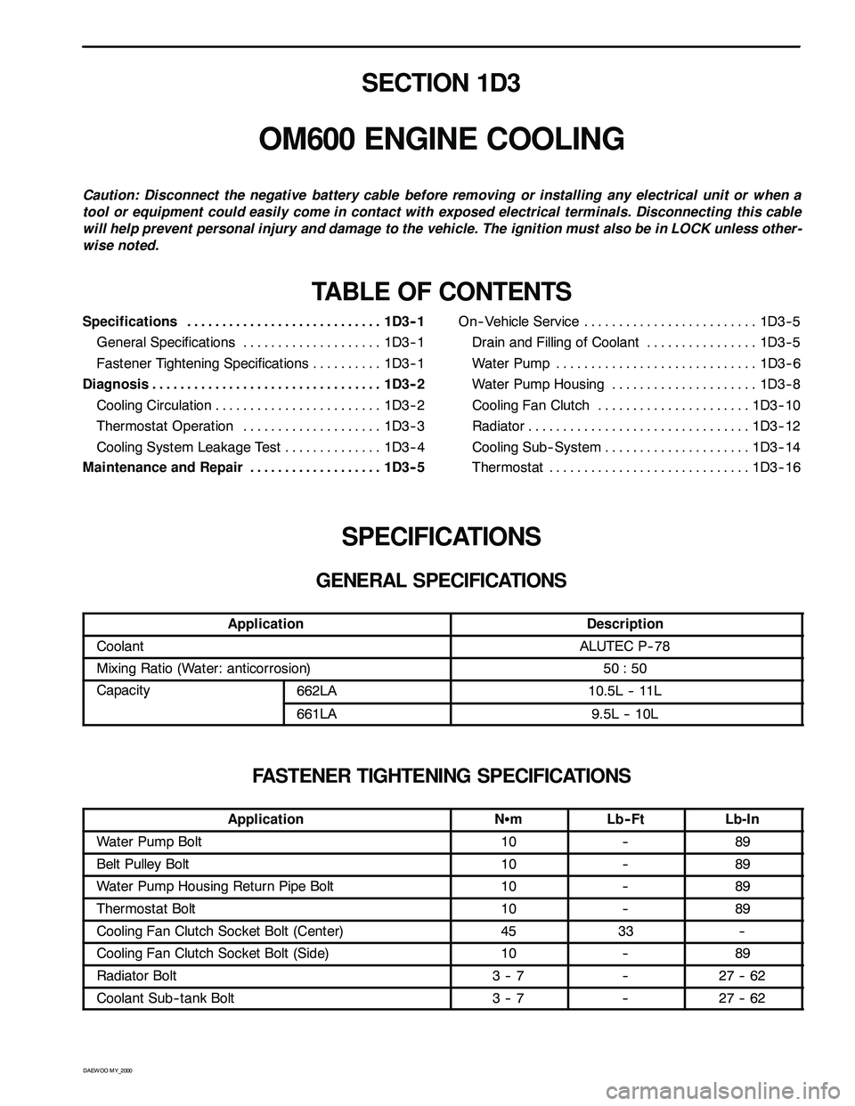
SECTION 1D3
OM600 ENGINE COOLING
Caution: Disconnect the negative battery cable before removing or installing any electrical unit or when a
tool or equipment could easily come in contact with exposed electrical terminals. Disconnecting this cable
will help prevent personal injury and damage to the vehicle. The ignition must also be in LOCK unless other -
wise noted.
TABLE OF CONTENTS
Specifications 1D3 -- 1............................
General Specifications 1D3-- 1....................
Fastener Tightening Specifications 1D3 -- 1..........
Diagnosis 1D3 -- 2.................................
Cooling Circulation 1D3 -- 2........................
Thermostat Operation 1D3 -- 3....................
Cooling System Leakage Test 1D3-- 4..............
Maintenance and Repair 1D3 -- 5...................On-- Vehicle Service 1D3-- 5.........................
Drain and Filling of Coolant 1D3 -- 5................
Wat er Pum p 1D3 -- 6.............................
Water Pump Housing 1D3-- 8.....................
Cooling Fan Clutch 1D3 -- 10......................
Radiator 1D3-- 12................................
Cooling Sub-- System 1D3-- 14.....................
Thermostat 1D3 -- 16.............................
SPECIFICATIONS
GENERAL SPECIFICATIONS
ApplicationDescription
CoolantALUTEC P-- 78
Mixing Ratio (Water: anticorrosion)50 : 50
Capacity662LA10.5L -- 11Lpy
661LA9.5L -- 10L
FASTENER TIGHTENING SPECIFICATIONS
ApplicationNSmLb-- FtLb-In
Water Pump Bolt10--89
Belt Pulley Bolt10--89
Water Pump Housing Return Pipe Bolt10--89
Thermostat Bolt10--89
Cooling Fan Clutch Socket Bolt (Center)4533--
Cooling Fan Clutch Socket Bolt (Side)10--89
Radiator Bolt3--7--27 -- 62
Coolant Sub-- tank Bolt3--7--27 -- 62
Page 1534 of 2053
MANUAL & SEMIAUTO-HVAC 7C-5
SSANGYONG MY2002
DEFECTIVES IN FAN MOTOR CIRCUIT
Fan Motor Does Not Run
Blown fuse
Battery voltage is low
Faulty wiring
Faulty groundChecksActionCheck for short and replace fuse.
Check battery voltage.
Check connectors’ connection.
Do not apply grease. This can cause voltage down.
Remove body painting and completely ground,
Tighten ground bolts and make sure body ground
connection.
Fan Motor Runs in ‘4’position Only (‘3’, ‘2’, ‘1’ : Does Not Run)
Motor Runs With Poor Blowing
Blown resister temperature fuse
Air leakage in parts connectionChecksActionReplace resistor.
Check heater, cooling unit and blower for proper
connection.
Clogged or blocked intake grilleChecksActionClogged or blocked intake grille reduces blowing
capacity.
Frosted Evaporator
Faulty thermo ampChecksActionFrosted evaporator reduces cooling capacity.
Off compressor and maximize blowing capacity
Page 1593 of 2053

SSANGYONG MY2002
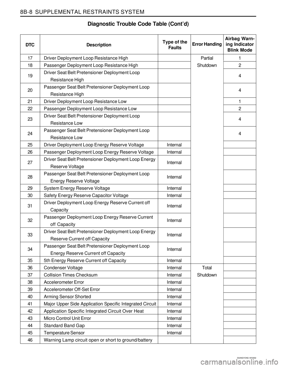
8B-8 SUPPLEMENTAL RESTRAINTS SYSTEM
Driver Deployment Loop Resistance High
Passenger Deployment Loop Resistance High
Driver Seat Belt Pretensioner Deployment Loop
Resistance High
Passenger Seat Belt Pretensioner Deployment Loop
Resistance High
Driver Deployment Loop Resistance Low
Passenger Deployment Loop Resistance Low
Driver Seat Belt Pretensioner Deployment Loop
Resistance Low
Passenger Seat Belt Pretensioner Deployment Loop
Resistance Low
Driver Deployment Loop Energy Reserve Voltage
Passenger Deployment Loop Energy Reserve Voltage
Driver Seat Belt Pretensioner Deployment Loop Energy
Reserve Voltage
Passenger Seat Belt Pretensioner Deployment Loop
Energy Reserve Voltage
System Energy Reserve Voltage
Safety Energy Reserve Capacitor Voltage
Driver Deployment Loop Energy Reserve Current off
Capacity
Passenger Deployment Loop Energy Reserve Current
off Capacity
Driver Seat Belt Pretensioner Deployment Loop Energy
Reserve Current off Capacity
Passenger Seat Belt Pretensioner Deployment Loop
Energy Reserve Current off Capacity
5th Energy Reserve Current off Capacity
Condenser Voltage
Collision Times Checksum
Accelerometer Error
Accelerometer Off-Set Error
Arming Sensor Shorted
Major Upper Side Application Specific Integrated Circuit
Application Specific Integrated Circuit Over Heat
Micro Control Unit Error
Standard Band Gap
Temperature Sensor
Warning Lamp circuit open or short to ground/battery 17
18
19
20
21
22
23
24
25
26
27
28
29
30
31
32
33
34
35
36
37
38
39
40
41
42
43
44
45
46
Diagnostic Trouble Code Table (Cont’d)
DTC DescriptionAirbag Warn-
ing Indicator
Blink Mode Error HandingType of the
Faults
Internal
Internal
Internal
Internal
Internal
Internal
Internal
Internal
Internal
Internal
Internal
Internal
Internal
Internal
Internal
Internal
Internal
Internal
Internal
Internal
Internal1
2
4
4
1
2
4
4
Partial
Shutdown
Total
Shutdown
Page 1656 of 2053

BODY WIRING SYSTEM 9A-5
SSANGYONG MY2002
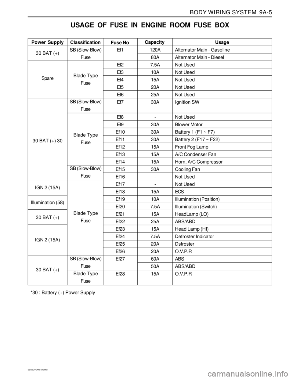
USAGE OF FUSE IN ENGINE ROOM FUSE BOX
Alternator Main - Gasoline
Alternator Main - Diesel
Not Used
Not Used
Not Used
Not Used
Not Used
Ignition SW
Not Used
Blower Motor
Battery 1 (F1 ~ F7)
Battery 2 (F17 ~ F22)
Front Fog Lamp
A/C Condenser Fan
Horn, A/C Compressor
Cooling Fan
Not Used
Not Used
ECS
Illumination (Position)
Illumination (Switch)
HeadLamp (LO)
ABS/ABD
Head Lamp (HI)
Defroster Indicator
Dsfroster
O.V.P.R
ABS
ABS/ABD
O.V.P.R Power SupplyUsage
Classification
Fuse NoCapacity
30 BAT (+)
Spare
30 BAT (+) 30
IGN 2 (15A)
Illumination (58)
30 BAT (+)
IGN 2 (15A)
30 BAT (+)SB (Slow-Blow)
Fuse
Blade Type
Fuse
SB (Slow-Blow)
Fuse
Blade Type
Fuse
SB (Slow-Blow)
Fuse
Blade Type
Fuse
SB (Slow-Blow)
Fuse
Blade Type
FuseEf1
Ef2
Ef3
Ef4
Ef5
Ef6
Ef7
Ef8
Ef9
Ef10
Ef11
Ef12
Ef13
Ef14
Ef15
Ef16
Ef17
Ef18
Ef19
Ef20
Ef21
Ef22
Ef23
Ef24
Ef25
Ef26
Ef27
Ef28120A
80A
7.5A
10A
15A
20A
25A
30A
-
30A
30A
30A
15A
15A
15A
30A
-
-
15A
10A
7.5A
15A
25A
15A
7.5A
20A
20A
60A
50A
15A
*30 : Battery (+) Power Supply