1997 SSANGYONG KORANDO fog light
[x] Cancel search: fog lightPage 13 of 2053

GENERAL INFORMATION 0B -- 13
D AEW OO M Y_2000
OWNER INSPECTIONS AND SERVICES
WHILE OPERATING THE VEHICLE
Horn Operation
Blow the horn occasionally to make sure it works. Check
all the button locations.
Brake System Operation
Be alert for abnormal sounds, increased brake pedal
travel or repeated puling to one side when braking. Also,
if the brake warning light goes on, or flashes, something
may be wrong with part of the brake system.
Exhaust System Operation
Be alert to any changes inthe sound of the system or
the smell of the fumes. These are signs that the system
may be leaking or overheating. Have the system in-
spected and repaired immediately.
Tires, Wheels and Alignment Operation
Be alert to any vibration of the steering wheel or the
seats at normal highway speeds. This may mean a
wheel needs to be balanced. Also, a pull right or left on a
straight, level road may show the need for a tire pres-
sure adjustment or a wheel alignment.
Steering System Operation
Be alert to changes in the steering action. An inspection
is needed when the steering wheel is hard to turn or has
too much free play, or is unusual sounds are noticed
when turning or parking.
Headlight Aim
Take note of the light pattern occasionally. Adjust the
headlights if the beams seem improperly aimed.
AT EACH FUEL FILL
A fluid loss in any (except windshield washer) system
may indicate a problem. Have the system inspected and
repaired immediately.
Engine Oil Level
Check the oil level and add oil if necessary. The best
time to check the engine oil level is when the oil is warm.
1. After stopping the engine, wait a few minutes for the
oil to drain back to the oil pan.
2. Pull out the oil level indicator (dip stick).
3. Wipe it clean, and push the oil level indicator back
down all the way.
4. Pull out the oil level indicator and look at the oil level
on it.
5. Add oil, if needed, to keep the oil level above the low-
er mark. Avoid overfilling theengine, since this may
cause engine damage.
6. Push the indicator all the way back down into the en-
gine after taking the reading.If you check the oil level when the oil is cold, do not run
the engine first. The cold oil will not drain back to the pan
fast enough to give a true oil level reading.
Engine Coolant Level and Condition
Check the coolant level in the coolant reservoir tank and
add coolant if necessary. Inspect the coolant. Replace
dirty or rusty coolant.
Windshield Washer Fluid Level
Check the washer fluid level in the reservoir. Add fluid if
necessary.
AT LEAST TWICE A MONTH
Tire And Wheel Inspection and Pressure
Check
Check the tire for abnormal wear or damage. Also check
for damaged wheels. Check the tire pressure when the
tires are cold ( check the spare also, unless it is a stow-
away). Maintain the recommended pressures. Refer to
“Tire and Wheel” is in section 0B.
AT LEAST MONTHLY
Light Operation
Check the operation of the license plate light, the head-
lights (including the high beams), the parking lights, the
fog lights, the taillight, the brake lights, the turn signals,
the backup lights and the hazard warning flasher.
Fluid Leak Check
Periodically inspect the surface beneath the vehicle for
water, oil, fuel or other fluids, after the vehicle has been
parked for a while. Water dripping from the air condition-
ing system after use is normal. If you notice fuel leaks or
fumes, find the cause and correct it at once.
AT LEAST TWICE A YEAR
Power Steering System Reservoir Level
Check the power steering fluid level. Keep the power
steering fluid at the proper level. Refer to Section 6A,
Power Steering System.
Brake Master Cylinder Reservoir Level
Check the fluid and keep it at the proper level. A low fluid
level can indicate worn disc brake pads which may need
to be serviced. Check the breather hole in the reservoir
cover to be free from dirt and check for an open pas-
sage.
Weather- Strip Lubrication
Apply a thin film silicone grease using a clean cloth.
Page 1664 of 2053
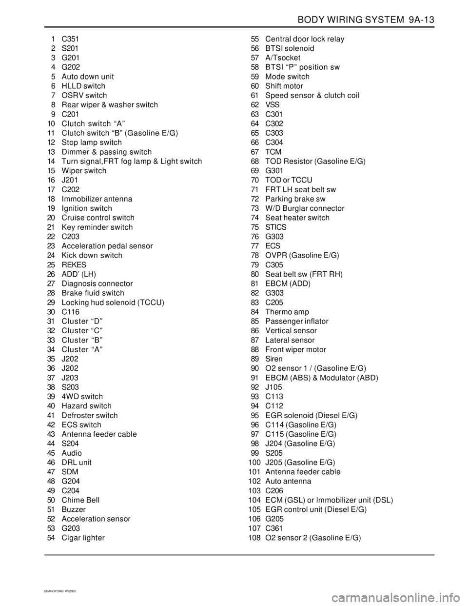
BODY WIRING SYSTEM 9A-13
SSANGYONG MY2002
1 C351
2 S201
3 G201
4 G202
5 Auto down unit
6 HLLD switch
7 OSRV switch
8 Rear wiper & washer switch
9 C201
10 Clutch switch “A”
11 Clutch switch “B” (Gasoline E/G)
12 Stop lamp switch
13 Dimmer & passing switch
14 Turn signal,FRT fog lamp & Light switch
15 Wiper switch
16 J201
17 C202
18 Immobilizer antenna
19 Ignition switch
20 Cruise control switch
21 Key reminder switch
22 C203
23 Acceleration pedal sensor
24 Kick down switch
25 REKES
26 ADD’ (LH)
27 Diagnosis connector
28 Brake fluid switch
29 Locking hud solenoid (TCCU)
30 C116
31 Cluster “D”
32 Cluster “C”
33 Cluster “B”
34 Cluster “A”
35 J202
36 J202
37 J203
38 S203
39 4WD switch
40 Hazard switch
41 Defroster switch
42 ECS switch
43 Antenna feeder cable
44 S204
45 Audio
46 DRL unit
47 SDM
48 G204
49 C204
50 Chime Bell
51 Buzzer
52 Acceleration sensor
53 G203
54 Cigar lighter55 Central door lock relay
56 BTSI solenoid
57 A/Tsocket
58 BTSI “P” position sw
59 Mode switch
60 Shift motor
61 Speed sensor & clutch coil
62 VSS
63 C301
64 C302
65 C303
66 C304
67 TCM
68 TOD Resistor (Gasoline E/G)
69 G301
70 TOD or TCCU
71 FRT LH seat belt sw
72 Parking brake sw
73 W/D Burglar connector
74 Seat heater switch
75 STICS
76 G303
77 ECS
78 OVPR (Gasoline E/G)
79 C305
80 Seat belt sw (FRT RH)
81 EBCM (ADD)
82 G303
83 C205
84 Thermo amp
85 Passenger inflator
86 Vertical sensor
87 Lateral sensor
88 Front wiper motor
89 Siren
90 O2 sensor 1 / (Gasoline E/G)
91 EBCM (ABS) & Modulator (ABD)
92 J105
93 C113
94 C112
95 EGR solenoid (Diesel E/G)
96 C114 (Gasoline E/G)
97 C115 (Gasoline E/G)
98 J204 (Gasoline E/G)
99 S205
100 J205 (Gasoline E/G)
101 Antenna feeder cable
102 Auto antenna
103 C206
104 ECM (GSL) or Immobilizer unit (DSL)
105 EGR control unit (Diesel E/G)
106 G205
107 C361
108 O2 sensor 2 (Gasoline E/G)
Page 1675 of 2053
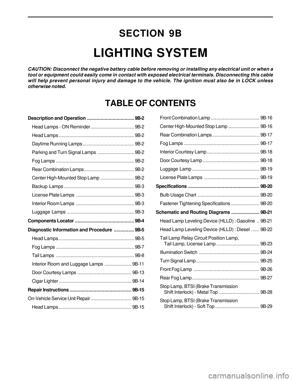
SECTION 9B
LIGHTING SYSTEM
CAUTION: Disconnect the negative battery cable before removing or installing any electrical unit or when a
tool or equipment could easily come in contact with exposed electrical terminals. Disconnecting this cable
will help prevent personal injury and damage to the vehicle. The ignition must also be in LOCK unless
otherwise noted.
TABLE OF CONTENTS
Description and Operation...................................9B-2
Head Lamps - ON Reminder................................9B-2
Head Lamps........................................................9B-2
Daytime Running Lamps......................................9B-2
Parking and Turn Signal Lamps...........................9B-2
Fog Lamps..........................................................9B-2
Rear Combination Lamps.....................................9B-2
Center High-Mounted Stop Lamp.........................9B-2
Backup Lamps....................................................9B-3
License Plate Lamps ...........................................9B-3
Interior Room Lamps ...........................................9B-3
Luggage Lamps..................................................9B-3
Components Locator............................................9B-4
Diagnostic Information and Procedure...............9B-5
Head Lamps........................................................9B-5
Fog Lamps..........................................................9B-7
Tail Lamps..........................................................9B-8
Interior Room and Luggage Lamps....................9B-11
Door Courtesy Lamps ........................................9B-13
Cigar Lighter......................................................9B-14
Repair Instructions..............................................9B-15
On-Vehicle Service Unit Repair..............................9B-15
Head Lamps......................................................9B-15Front Combination Lamp....................................9B-16
Center High-Mounted Stop Lamp.......................9B-16
Rear Combination Lamps...................................9B-17
Fog Lamps........................................................9B-17
Interior Courtesy Lamp .......................................9B-18
Door Courtesy Lamp ..........................................9B-18
Luggage Lamp..................................................9B-19
License Plate Lamps .........................................9B-19
Specifications.....................................................9B-20
Bulb Usage Chart..............................................9B-20
Fastener Tightening Specifications.....................9B-20
Schematic and Routing Diagrams.....................9B-21
Head Lamp Leveling Device (HLLD) : Gasoline ..9B-21
Head Lamp Leveling Device (HLLD) : Diesel......9B-22
Tail Lamp Relay Circuit Position Lamp,
Tail Lamp, License Lamp................................9B-23
Illumination Switch.............................................9B-24
Turn Signal Lamp...............................................9B-25
Front Fog Lamp.................................................9B-26
Rear Fog Lamp..................................................9B-27
Stop Lamp, BTSI (Brake Transmission
Shift Interlock) - Metal Top..............................9B-28
Stop Lamp, BTSI (Brake Transmission
Shift Interlock) - Soft Top.................................9B-29
Page 1676 of 2053
SSANGYONG MY2002
9B-2 LIGHTING SYSTEM
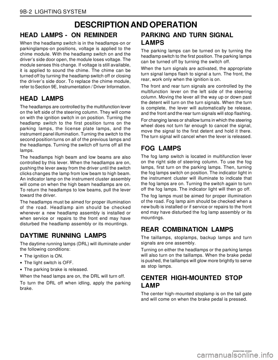
DESCRIPTION AND OPERATION
HEAD LAMPS - ON REMINDER
When the headlamp switch is in the headlamps-on or
parkinglamps-on positions, voltage is applied to the
chime module. With the headlamp switch on and the
driver’s side door open, the module loses voltage. The
module senses this change. If voltage is still available,
it is applied to sound the chime. The chime can be
turned off by turning the headlamp switch off or closing
the driver’s side door. To replace the chime module,
refer to Section 9E, Instrumentation / Driver Information.
HEAD LAMPS
The headlamps are controlled by the multifunction lever
on the left side of the steering column. They will come
on with the ignition switch in on position. Turning the
headlamp switch to the first position turns on the
parking lamps, the license plate lamps, and the
instrument panel illumination. Turning the switch to the
second position turns on all of the previous lamps and
the headlamps. Turning the switch off turns off all the
lamps.
The headlamps high beam and low beams are also
controlled by this lever. When the headlamps are on,
pushing the lever away from the driver until the switch
clicks changes the lamp from low beam to high beam.
An indicator lamp on the instrument cluster assembly
will come on when the high beam headlamps are on.
To return the headlamps to low beams, pull the lever
toward the driver.
The headlamps must be aimed for proper illumination
of the road. Headlamp aim should be checked
whenever a new headlamp assembly is installed or
when service or repairs to the front end may have
disturbed the headlamp assembly or its mountings.
DAYTIME RUNNING LAMPS
The daytime running lamps (DRL) will illuminate under
the following conditions:
The ignition is ON.
The light switch is OFF.
The parking brake is released.
When the head lamps are on, the DRL will turn off.
To turn the DRL off when idling, apply the parking
brake.
PARKING AND TURN SIGNAL
LAMPS
The parking lamps can be turned on by turning the
headlamp switch to the first position. The parking lamps
can be turned off by turning the switch off.
When the turn signals are activated, the appropriate
turn signal lamps flash to signal a turn. The front, the
rear, work only when the ignition is on.
The front and rear turn signals are controlled by the
multifunction lever on the left side of the steering
column. Moving the lever all the way up or down past
the detent will turn on the turn signals. When the turn
is complete, the lever will automatically be release,
and the front and the rear turn signals will stop flashing.
For changing lanes or shallow turns in which the steering
wheel does not turn far enough to cancel the signal,
move the signal to the first detent and hold it there.
The turn signal will cancel when the lever is released.
FOG LAMPS
The fog lamp switch is located in multifunction lever
on the right side of steering column. To use the fog
lamps, first turn on the parking lamps. Then, turning
the fog lamps switch on position. The indicator light in
the instrument cluster will illuminate to indicate that
the fog lamps are on. Turning the switch again to turn
off the fog lamps. The indicator light will then go off.
The fog lamps must be aimed for proper illumination
of the road. Fog lamp aim should be checked when a
new bulb is installed or if service or repairs to the front
end may have disturbed the fog lamp assembly or its
mountings.
REAR COMBINATION LAMPS
The taillamps, stoplamps, backup lamps and turn
signals are one assembly.
Turning on either the headlamps or the parking lamps
will also turn on the taillamps. When the brake pedal
is pushed, the taillamps will glow more brightly to serve
as stop lamps.
CENTER HIGH-MOUNTED STOP
LAMP
The center high-mounted stoplamp is on the tail gate
and will come on when the brake pedal is pressed.
Page 1679 of 2053
LIGHTING SYSTEM 9B-5
SSANGYONG MY2002
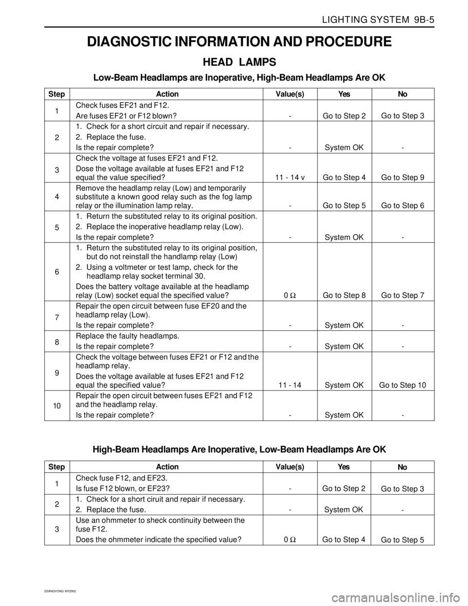
DIAGNOSTIC INFORMATION AND PROCEDURE
HEAD LAMPS
Low-Beam Headlamps are Inoperative, High-Beam Headlamps Are OK
Step
1
2
3
4
5
6
7
8
9
10Action
Check fuses EF21 and F12.
Are fuses EF21 or F12 blown?
1. Check for a short circuit and repair if necessary.
2. Replace the fuse.
Is the repair complete?
Check the voltage at fuses EF21 and F12.
Dose the voltage available at fuses EF21 and F12
equal the value specified?
Remove the headlamp relay (Low) and temporarily
substitute a known good relay such as the fog lamp
relay or the illumination lamp relay.
1. Return the substituted relay to its original position.
2. Replace the inoperative headlamp relay (Low).
Is the repair complete?
1. Return the substituted relay to its original position,
but do not reinstall the handlamp relay (Low)
2. Using a voltmeter or test lamp, check for the
headlamp relay socket terminal 30.
Does the battery voltage available at the headlamp
relay (Low) socket equal the specified value?
Repair the open circuit between fuse EF20 and the
headlamp relay (Low).
Is the repair complete?
Replace the faulty headlamps.
Is the repair complete?
Check the voltage between fuses EF21 or F12 and the
headlamp relay.
Does the voltage available at fuses EF21 and F12
equal the specified value?
Repair the open circuit between fuses EF21 and F12
and the headlamp relay.
Is the repair complete?Yes
Go to Step 2
System OK
Go to Step 4
Go to Step 5
System OK
Go to Step 8
System OK
System OK
System OK
System OKNo
Go to Step 3
-
Go to Step 9
Go to Step 6
-
Go to Step 7
-
-
Go to Step 10
- Value(s)
-
-
11 - 14 v
-
-
0 Ω
-
-
11 - 14
-
High-Beam Headlamps Are Inoperative, Low-Beam Headlamps Are OK
Step
1
2
3Action
Check fuse F12, and EF23.
Is fuse F12 blown, or EF23?
1. Check for a short ciruit and repair if necessary.
2. Replace the fuse.
Use an ohmmeter to sheck continuity between the
fuse F12.
Does the ohmmeter indicate the specified value?Yes
Go to Step 2
System OK
Go to Step 4No
Go to Step 3
-
Go to Step 5 Value(s)
-
-
0 Ω
Page 1681 of 2053
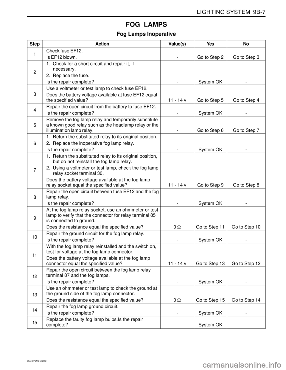
LIGHTING SYSTEM 9B-7
SSANGYONG MY2002
Step
1
2
3
4
5
6
7
8
9
10
11
12
13
14
15Action
Check fuse EF12.
Is EF12 blown.
1. Check for a short circuit and repair it, if
necessary.
2. Replace the fuse.
Is the repair complete?
Use a voltmeter or test lamp to check fuse EF12.
Does the battery voltage available at fuse EF12 equal
the specified value?
Repair the open circuit from the battery to fuse EF12.
Is the repair complete?
Remove the fog lamp relay and temporarily substitute
a known good relay such as the headlamp relay or the
illumination lamp relay.
1. Return the substituted relay to its original position.
2. Replace the inoperative fog lamp relay.
Is the repair complete?
1. Return the substituted relay to its original position,
but do not reinstall the fog lamp relay.
2. Using a voltmeter or test lamp, check the fog lamp
relay socket terminal 30.
Does the battery voltage available at the fog lamp
relay socket equal the specified value?
Repair the open circuit between fuse EF12 and the fog
lamp relay.
Is the repair complete?
At the fog lamp relay socket, use an ohmmeter or test
lamp to verify that the connector for relay terminal 85
is connected to ground.
Does the resistance equal the specified value?
Repair the ground circuit for the fog lamp relay.
Is the repair complete?
With the fog lamp relay reinstalled and the switch on,
test for voltage at the fog lamp connector.
Does the battery voltage available at the fog lamp
connector equal the specified value?
Repair the open circuit between the fog lamp relay
terminal 87 and the fog lamps.
Is the repair complete?
Use an ohmmeter or test lamp to check the ground at
the ground side of the fog lamp connector.
Does the resistance equal the specified value?
Repair the fog lamp ground circuit.
Is the repair complete?
Replace the faulty fog lamp bulbs.Is the repair
complete?Yes
Go to Step 2
System OK
Go to Step 5
System OK
Go to Step 6
System OK
Go to Step 9
System OK
Go to Step 11
System OK
Go to Step 13
System OK
Go to Step 15
System OK
System OKNo
Go to Step 3
-
Go to Step 4
-
Go to Step 7
-
Go to Step 8
-
Go to Step 10
-
Go to Step 12
-
Go to Step 14
-
- Value(s)
-
-
11 - 14 v
-
-
-
11 - 14 v
-
0 Ω
-
11 - 14 v
-
0 Ω
-
-
FOG LAMPS
Fog Lamps Inoperative
Page 1691 of 2053
LIGHTING SYSTEM 9B-17
SSANGYONG MY2002
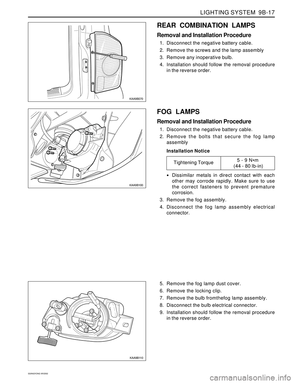
KAA9B070
REAR COMBINATION LAMPS
Removal and Installation Procedure
1. Disconnect the negative battery cable.
2. Remove the screws and the lamp assembly
3. Remove any inoperative bulb.
4. Installation should follow the removal procedure
in the reverse order.
KAA9B100
FOG LAMPS
Removal and Installation Procedure
1. Disconnect the negative battery cable.
2. Remove the bolts that secure the fog lamp
assembly
Installation Notice
Dissimilar metals in direct contact with each
other may corrode rapidly. Make sure to use
the correct fasteners to prevent premature
corrosion.
3. Remove the fog assembly.
4. Disconnect the fog lamp assembly electrical
connector.
Tightening Torque5 - 9 Nm
(44 - 80 lb-in)
KAA9B110
5. Remove the fog lamp dust cover.
6. Remove the locking clip.
7. Remove the bulb fromthefog lamp assembly.
8. Disconnect the bulb electrical connector.
9. Installation should follow the removal procedure
in the reverse order.
Page 1694 of 2053
SSANGYONG MY2002
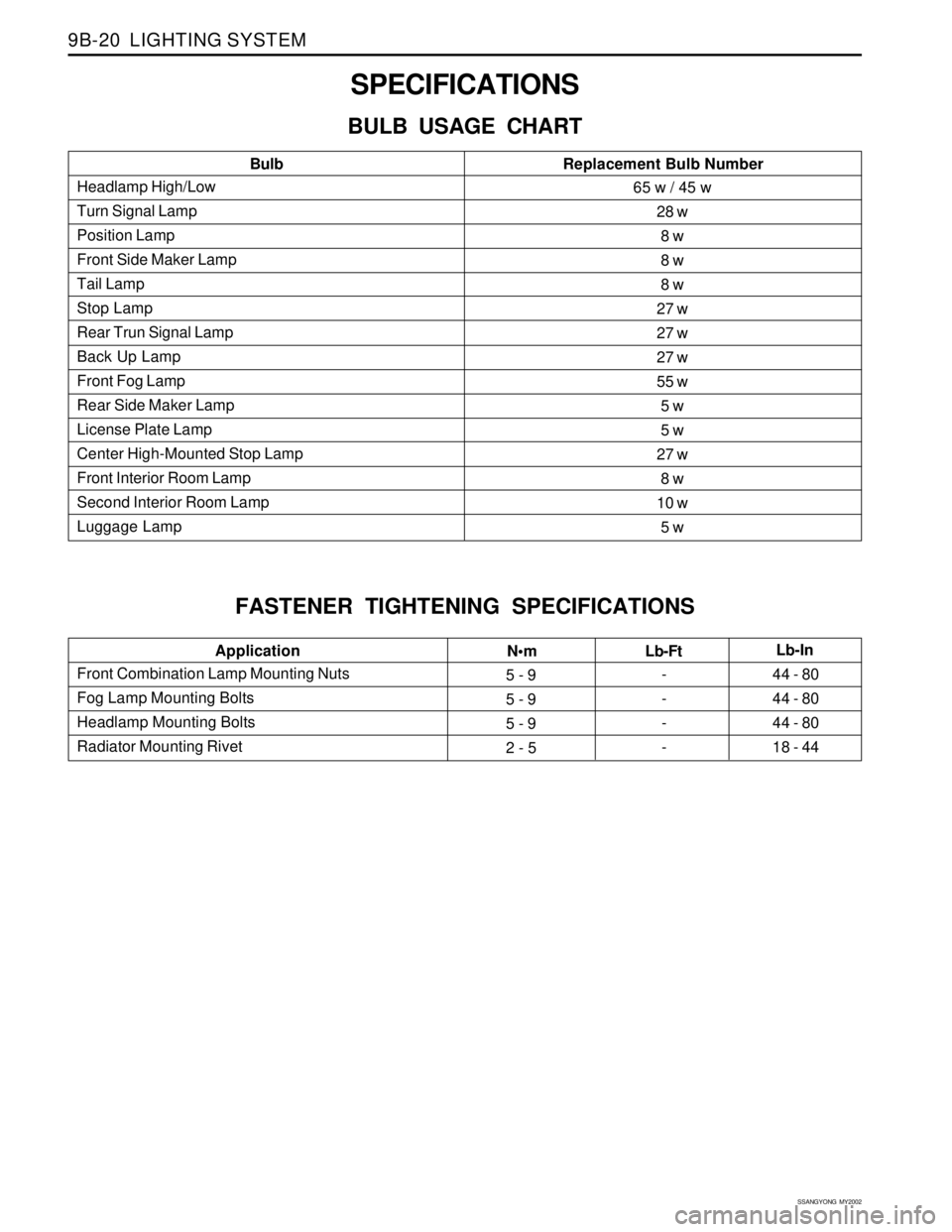
9B-20 LIGHTING SYSTEM
SPECIFICATIONS
BULB USAGE CHART
FASTENER TIGHTENING SPECIFICATIONS
Headlamp High/Low
Turn Signal Lamp
Position Lamp
Front Side Maker Lamp
Tail Lamp
Stop Lamp
Rear Trun Signal Lamp
Back Up Lamp
Front Fog Lamp
Rear Side Maker Lamp
License Plate Lamp
Center High-Mounted Stop Lamp
Front Interior Room Lamp
Second Interior Room Lamp
Luggage LampBulbReplacement Bulb Number65 w / 45 w
28 w
8 w
8 w
8 w
27 w
27 w
27 w
55 w
5 w
5 w
27 w
8 w
10 w
5 w
Front Combination Lamp Mounting Nuts
Fog Lamp Mounting Bolts
Headlamp Mounting Bolts
Radiator Mounting RivetApplication
Nm
5 - 9
5 - 9
5 - 9
2 - 5-
-
-
-44 - 80
44 - 80
44 - 80
18 - 44 Lb-FtLb-In