1997 SSANGYONG KORANDO back door repair
[x] Cancel search: back door repairPage 858 of 2053
SSANGYONG MY2002
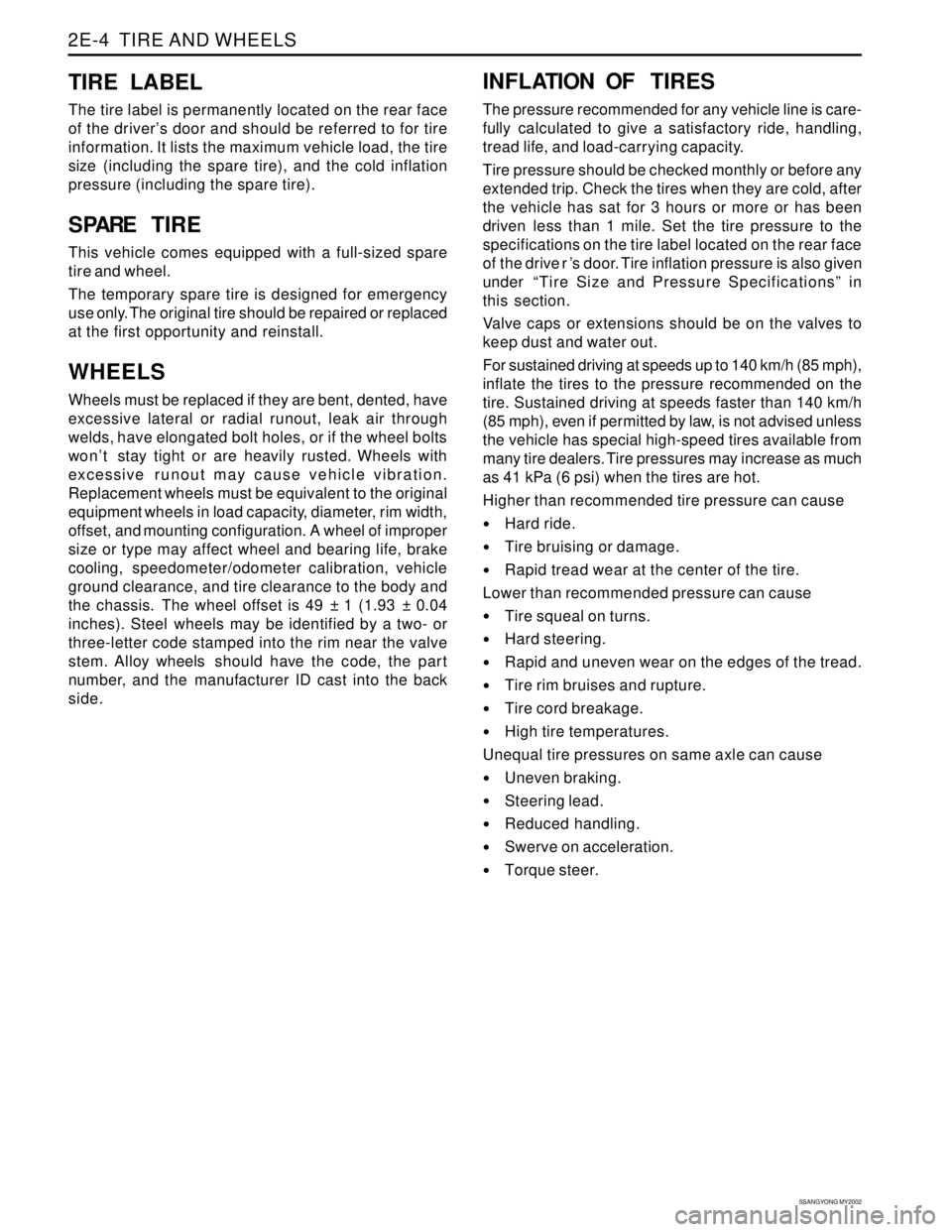
2E-4 TIRE AND WHEELS
TIRE LABEL
The tire label is permanently located on the rear face
of the driver’s door and should be referred to for tire
information. It lists the maximum vehicle load, the tire
size (including the spare tire), and the cold inflation
pressure (including the spare tire).
S PARE TIRE
This vehicle comes equipped with a full-sized spare
tire and wheel.
The temporary spare tire is designed for emergency
use only. The original tire should be repaired or replaced
at the first opportunity and reinstall.
WHEELS
Wheels must be replaced if they are bent, dented, have
excessive lateral or radial runout, leak air through
welds, have elongated bolt holes, or if the wheel bolts
won’t stay tight or are heavily rusted. Wheels with
excessive runout may cause vehicle vibration.
Replacement wheels must be equivalent to the original
equipment wheels in load capacity, diameter, rim width,
offset, and mounting configuration. A wheel of improper
size or type may affect wheel and bearing life, brake
cooling, speedometer/odometer calibration, vehicle
ground clearance, and tire clearance to the body and
the chassis. The wheel offset is 49 ± 1 (1.93 ± 0.04
inches). Steel wheels may be identified by a two- or
three-letter code stamped into the rim near the valve
stem. Alloy wheels should have the code, the part
number, and the manufacturer ID cast into the back
side.
INFLATION OF TIRES
The pressure recommended for any vehicle line is care-
fully calculated to give a satisfactory ride, handling,
tread life, and load-carrying capacity.
Tire pressure should be checked monthly or before any
extended trip. Check the tires when they are cold, after
the vehicle has sat for 3 hours or more or has been
driven less than 1 mile. Set the tire pressure to the
specifications on the tire label located on the rear face
of the drive r ’s door. Tire inflation pressure is also given
under “Tire Size and Pressure Specifications” in
this section.
Valve caps or extensions should be on the valves to
keep dust and water out.
For sustained driving at speeds up to 140 km/h (85 mph),
inflate the tires to the pressure recommended on the
tire. Sustained driving at speeds faster than 140 km/h
(85 mph), even if permitted by law, is not advised unless
the vehicle has special high-speed tires available from
many tire dealers. Tire pressures may increase as much
as 41 kPa (6 psi) when the tires are hot.
Higher than recommended tire pressure can cause
Hard ride.
Tire bruising or damage.
Rapid tread wear at the center of the tire.
Lower than recommended pressure can cause
Tire squeal on turns.
Hard steering.
Rapid and uneven wear on the edges of the tread.
Tire rim bruises and rupture.
Tire cord breakage.
High tire temperatures.
Unequal tire pressures on same axle can cause
Uneven braking.
Steering lead.
Reduced handling.
Swerve on acceleration.
Torque steer.
Page 1507 of 2053
SSANGYONG MY2002
7A-6 HEATING AND VENTILATION SYSTEM
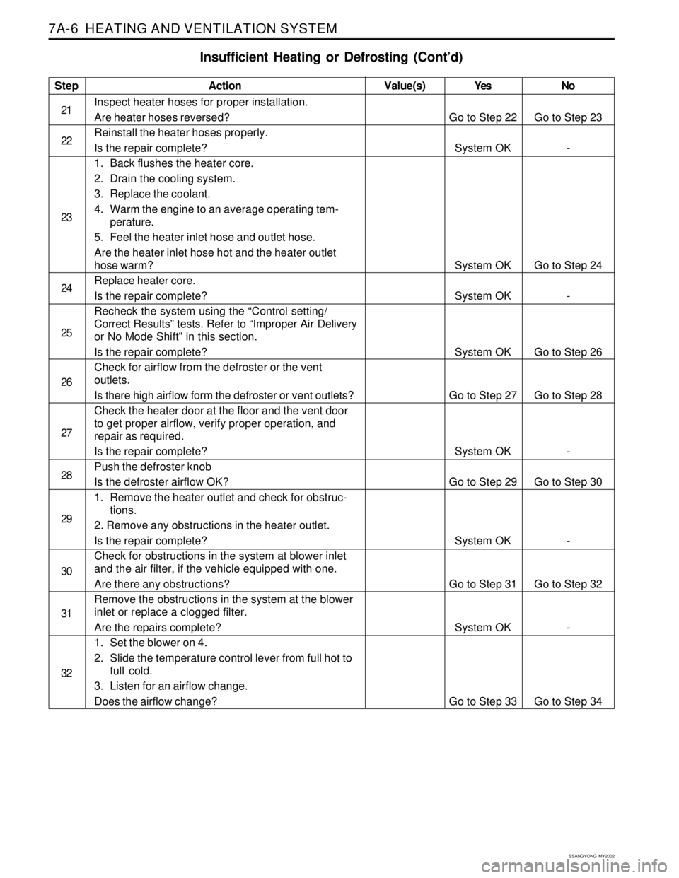
Insufficient Heating or Defrosting (Cont’d)
Step
21
22
23
24
25
26
27
28
29
30
31
32Action
Inspect heater hoses for proper installation.
Are heater hoses reversed?
Reinstall the heater hoses properly.
Is the repair complete?
1. Back flushes the heater core.
2. Drain the cooling system.
3. Replace the coolant.
4. Warm the engine to an average operating tem-
perature.
5. Feel the heater inlet hose and outlet hose.
Are the heater inlet hose hot and the heater outlet
hose warm?
Replace heater core.
Is the repair complete?
Recheck the system using the “Control setting/
Correct Results” tests. Refer to “Improper Air Delivery
or No Mode Shift” in this section.
Is the repair complete?
Check for airflow from the defroster or the vent
outlets.
Is there high airflow form the defroster or vent outlets?
Check the heater door at the floor and the vent door
to get proper airflow, verify proper operation, and
repair as required.
Is the repair complete?
Push the defroster knob
Is the defroster airflow OK?
1. Remove the heater outlet and check for obstruc-
tions.
2. Remove any obstructions in the heater outlet.
Is the repair complete?
Check for obstructions in the system at blower inlet
and the air filter, if the vehicle equipped with one.
Are there any obstructions?
Remove the obstructions in the system at the blower
inlet or replace a clogged filter.
Are the repairs complete?
1. Set the blower on 4.
2. Slide the temperature control lever from full hot to
full cold.
3. Listen for an airflow change.
Does the airflow change?Yes
Go to Step 22
System OK
System OK
System OK
System OK
Go to Step 27
System OK
Go to Step 29
System OK
Go to Step 31
System OK
Go to Step 33No
Go to Step 23
-
Go to Step 24
-
Go to Step 26
Go to Step 28
-
Go to Step 30
-
Go to Step 32
-
Go to Step 34 Value(s)
Page 1675 of 2053
SECTION 9B
LIGHTING SYSTEM
CAUTION: Disconnect the negative battery cable before removing or installing any electrical unit or when a
tool or equipment could easily come in contact with exposed electrical terminals. Disconnecting this cable
will help prevent personal injury and damage to the vehicle. The ignition must also be in LOCK unless
otherwise noted.
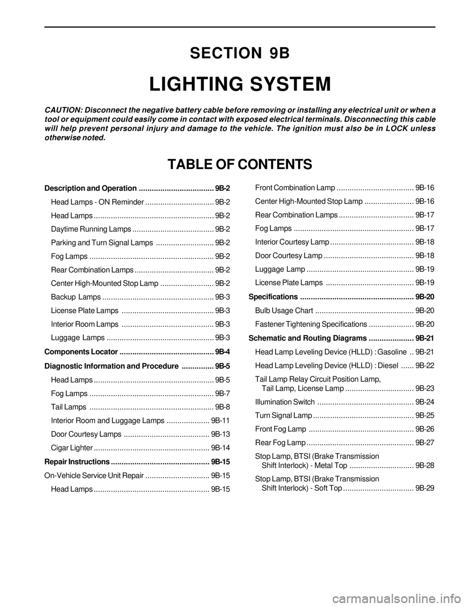
TABLE OF CONTENTS
Description and Operation...................................9B-2
Head Lamps - ON Reminder................................9B-2
Head Lamps........................................................9B-2
Daytime Running Lamps......................................9B-2
Parking and Turn Signal Lamps...........................9B-2
Fog Lamps..........................................................9B-2
Rear Combination Lamps.....................................9B-2
Center High-Mounted Stop Lamp.........................9B-2
Backup Lamps....................................................9B-3
License Plate Lamps ...........................................9B-3
Interior Room Lamps ...........................................9B-3
Luggage Lamps..................................................9B-3
Components Locator............................................9B-4
Diagnostic Information and Procedure...............9B-5
Head Lamps........................................................9B-5
Fog Lamps..........................................................9B-7
Tail Lamps..........................................................9B-8
Interior Room and Luggage Lamps....................9B-11
Door Courtesy Lamps ........................................9B-13
Cigar Lighter......................................................9B-14
Repair Instructions..............................................9B-15
On-Vehicle Service Unit Repair..............................9B-15
Head Lamps......................................................9B-15Front Combination Lamp....................................9B-16
Center High-Mounted Stop Lamp.......................9B-16
Rear Combination Lamps...................................9B-17
Fog Lamps........................................................9B-17
Interior Courtesy Lamp .......................................9B-18
Door Courtesy Lamp ..........................................9B-18
Luggage Lamp..................................................9B-19
License Plate Lamps .........................................9B-19
Specifications.....................................................9B-20
Bulb Usage Chart..............................................9B-20
Fastener Tightening Specifications.....................9B-20
Schematic and Routing Diagrams.....................9B-21
Head Lamp Leveling Device (HLLD) : Gasoline ..9B-21
Head Lamp Leveling Device (HLLD) : Diesel......9B-22
Tail Lamp Relay Circuit Position Lamp,
Tail Lamp, License Lamp................................9B-23
Illumination Switch.............................................9B-24
Turn Signal Lamp...............................................9B-25
Front Fog Lamp.................................................9B-26
Rear Fog Lamp..................................................9B-27
Stop Lamp, BTSI (Brake Transmission
Shift Interlock) - Metal Top..............................9B-28
Stop Lamp, BTSI (Brake Transmission
Shift Interlock) - Soft Top.................................9B-29
Page 1676 of 2053
SSANGYONG MY2002
9B-2 LIGHTING SYSTEM
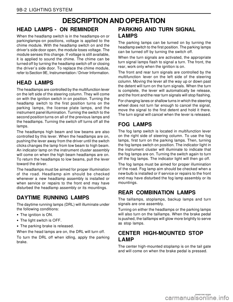
DESCRIPTION AND OPERATION
HEAD LAMPS - ON REMINDER
When the headlamp switch is in the headlamps-on or
parkinglamps-on positions, voltage is applied to the
chime module. With the headlamp switch on and the
driver’s side door open, the module loses voltage. The
module senses this change. If voltage is still available,
it is applied to sound the chime. The chime can be
turned off by turning the headlamp switch off or closing
the driver’s side door. To replace the chime module,
refer to Section 9E, Instrumentation / Driver Information.
HEAD LAMPS
The headlamps are controlled by the multifunction lever
on the left side of the steering column. They will come
on with the ignition switch in on position. Turning the
headlamp switch to the first position turns on the
parking lamps, the license plate lamps, and the
instrument panel illumination. Turning the switch to the
second position turns on all of the previous lamps and
the headlamps. Turning the switch off turns off all the
lamps.
The headlamps high beam and low beams are also
controlled by this lever. When the headlamps are on,
pushing the lever away from the driver until the switch
clicks changes the lamp from low beam to high beam.
An indicator lamp on the instrument cluster assembly
will come on when the high beam headlamps are on.
To return the headlamps to low beams, pull the lever
toward the driver.
The headlamps must be aimed for proper illumination
of the road. Headlamp aim should be checked
whenever a new headlamp assembly is installed or
when service or repairs to the front end may have
disturbed the headlamp assembly or its mountings.
DAYTIME RUNNING LAMPS
The daytime running lamps (DRL) will illuminate under
the following conditions:
The ignition is ON.
The light switch is OFF.
The parking brake is released.
When the head lamps are on, the DRL will turn off.
To turn the DRL off when idling, apply the parking
brake.
PARKING AND TURN SIGNAL
LAMPS
The parking lamps can be turned on by turning the
headlamp switch to the first position. The parking lamps
can be turned off by turning the switch off.
When the turn signals are activated, the appropriate
turn signal lamps flash to signal a turn. The front, the
rear, work only when the ignition is on.
The front and rear turn signals are controlled by the
multifunction lever on the left side of the steering
column. Moving the lever all the way up or down past
the detent will turn on the turn signals. When the turn
is complete, the lever will automatically be release,
and the front and the rear turn signals will stop flashing.
For changing lanes or shallow turns in which the steering
wheel does not turn far enough to cancel the signal,
move the signal to the first detent and hold it there.
The turn signal will cancel when the lever is released.
FOG LAMPS
The fog lamp switch is located in multifunction lever
on the right side of steering column. To use the fog
lamps, first turn on the parking lamps. Then, turning
the fog lamps switch on position. The indicator light in
the instrument cluster will illuminate to indicate that
the fog lamps are on. Turning the switch again to turn
off the fog lamps. The indicator light will then go off.
The fog lamps must be aimed for proper illumination
of the road. Fog lamp aim should be checked when a
new bulb is installed or if service or repairs to the front
end may have disturbed the fog lamp assembly or its
mountings.
REAR COMBINATION LAMPS
The taillamps, stoplamps, backup lamps and turn
signals are one assembly.
Turning on either the headlamps or the parking lamps
will also turn on the taillamps. When the brake pedal
is pushed, the taillamps will glow more brightly to serve
as stop lamps.
CENTER HIGH-MOUNTED STOP
LAMP
The center high-mounted stoplamp is on the tail gate
and will come on when the brake pedal is pressed.
Page 1770 of 2053
SSANGYONG MY2002
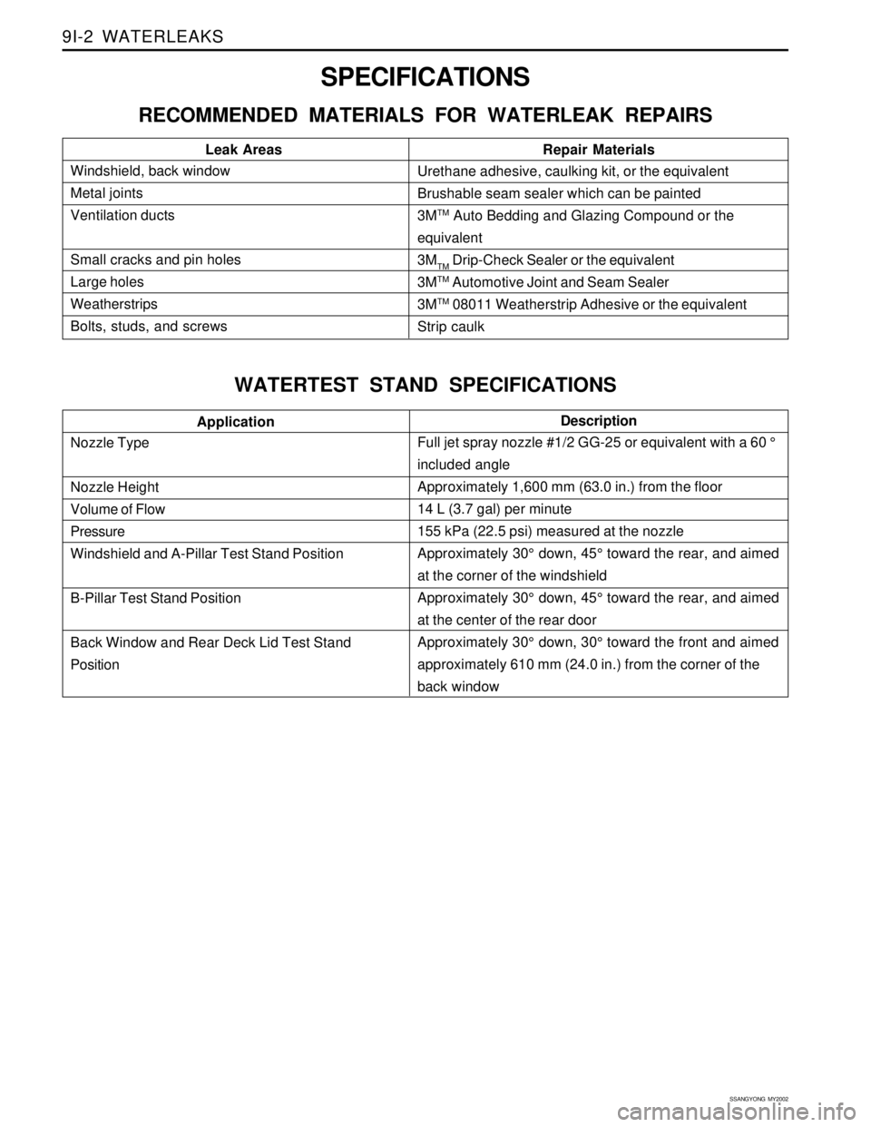
9I-2 WATERLEAKS
Description
SPECIFICATIONS
RECOMMENDED MATERIALS FOR WATERLEAK REPAIRS
WATERTEST STAND SPECIFICATIONS
Windshield, back window
Metal joints
Ventilation ducts
Small cracks and pin holes
Large holes
Weatherstrips
Bolts, studs, and screwsLeak Areas Repair MaterialsUrethane adhesive, caulking kit, or the equivalent
Brushable seam sealer which can be painted
3M
TM Auto Bedding and Glazing Compound or the
equivalent
3M
TM Drip-Check Sealer or the equivalent
3M
TM Automotive Joint and Seam Sealer
3M
TM 08011 Weatherstrip Adhesive or the equivalent
Strip caulk
Nozzle Type
Nozzle Height
Volume of Flow
Pressure
Windshield and A-Pillar Test Stand Position
B-Pillar Test Stand Position
Back Window and Rear Deck Lid Test Stand
PositionApplication
Full jet spray nozzle #1/2 GG-25 or equivalent with a 60 °
included angle
Approximately 1,600 mm (63.0 in.) from the floor
14 L (3.7 gal) per minute
155 kPa (22.5 psi) measured at the nozzle
Approximately 30° down, 45° toward the rear, and aimed
at the corner of the windshield
Approximately 30° down, 45° toward the rear, and aimed
at the center of the rear door
Approximately 30° down, 30° toward the front and aimed
approximately 610 mm (24.0 in.) from the corner of the
back window
Page 1783 of 2053
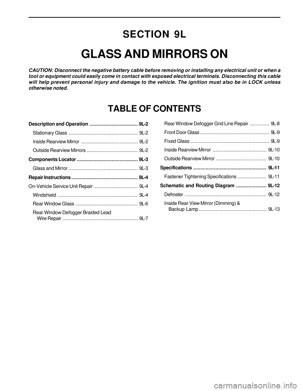
SECTION 9L
GLASS AND MIRRORS ON
CAUTION: Disconnect the negative battery cable before removing or installing any electrical unit or when a
tool or equipment could easily come in contact with exposed electrical terminals. Disconnecting this cable
will help prevent personal injury and damage to the vehicle. The ignition must also be in LOCK unless
otherwise noted.
TABLE OF CONTENTS
Description and Operation...................................9L-2
Stationary Glass..................................................9L-2
Inside Rearview Mirror.........................................9L-2
Outside Rearview Mirrors.....................................9L-2
Components Locator............................................9L-3
Glass and Mirror..................................................9L-3
Repair Instructions................................................9L-4
On-Vehicle Service Unit Repair................................9L-4
Windshield..........................................................9L-4
Rear Window Glass.............................................9L-6
Rear Window Defogger Braided Lead
Wire Repair......................................................9L-7Rear Window Defogger Grid Line Repair..............9L-8
Front Door Glass..................................................9L-9
Fixed Glass.........................................................9L-9
Inside Rearview Mirror ....................................... 9L-10
Outside Rearview Mirror..................................... 9L-10
Specifications.....................................................9L-11
Fastener Tightening Specifications..................... 9L-11
Schematic and Routing Diagram......................9L-12
Defroster........................................................... 9L-12
Inside Rear View Mirror (Dimming) &
Backup Lamp................................................. 9L-13