1997 SSANGYONG KORANDO door lock
[x] Cancel search: door lockPage 14 of 2053

0B -- 14 GENERAL INFORMATION
D AEW OO M Y_2000
EACH TIME THE OIL IS CHANGED
Brake System Inspection
This inspection should be done when the wheels are re-
moved for rotation. Inspect the lines and the hoses for
proper hookup, binding, leaks, cracks, chafing, etc. In-
spect the disc brake pads for wear. Inspect the rotors for
surface condition. Inspect other brake parts, the parking
brake, etc., at the same time. Inspect the brakes more
often if habit or conditions result in frequent braking.
Steering, Suspension and Front Drive Axle
Boot And Seal Inspection
Inspect the front and rear suspension and the steering
system for damaged, loose or missing parts, signs of
wear or lack of lubrication. Inspect the power steering
line and the hoses for proper hookup, binding, leaks,
cracks, chafing, etc. Clean and inspect the drive axle
boot and seals for damage, tears or leakage. Replace
the seals if necessary.
Exhaust System Inspection
Inspect the complete system (including the catalytic
converter if equipped). Inspect the body near the ex-
haust system. Look for broken, damaged, missing, or
out -- of -- position parts as well as open seams, holes,
loose connections, or other conditions which could
cause heat buildup in the floor pan or could let exhaust
fumes seep into the trunk or passenger compartment.
Throttle Linkage Inspection
Inspect the throttle linkage for interference or binding,
damaged, or missing parts. Lubricate all linkage joints
and throttle cable joints, the intermediate throttle shaft
bearing, the return spring at throttle valve assembly, and
the accelerator pedal sliding face with suitable grease.
Check the throttle cable for free movements.
Engine Drive Belts
Inspect all belts for cracks, fraying, wear and proper ten-
sion. Adjust or replace the belts as needed.
Hood Latch Operation
When opening the hood, note the operation of the sec-
ondary latch. It should keep the hood from opening all
the way when the primary latch is released. The hood
must close firmly.
AT LEAST ANNUALLY
Lap and Shoulder Belts Condition and Operation
Inspect the belt system including: the webbing, the
buckles, the latch plates, the retractor, the guide loops
and the anchors.
Movable Head Restraint Operation
On vehicles with movable head restraints, the restraints
must stay in the desired position.
Spare Tire and Jack Storage
Be alert to rattles in the rear of the vehicle. The spare
tire, all the jacking equipment, and the tools must be se-
curely stowed at all times. Oil the jack ratchet or the
screw mechanism after each use.
Key Lock Service
Lubricate the key lock cylinder.
Body Lubrication Service
Lubricate all the body door hinges including the hood,
the fuel door, the rear compartment hinges and the
latches, the glove box and the console doors, and any
folding seat hardware.
Underbody Flushing
Flushing the underbody will remove any corrosive mate-
rials used for ice and snow removal and dust control. At
least every spring clean the underbody. First, loosen the
sediment packed in closed areas of the vehicle. Then
flush the underbody with plain water.
Engine Cooling System
Inspect the coolant and freeze protection fluid. If the
fluid is dirty or rusty, drain, flush and refill the engine
cooling system with new coolant. Keep the coolant at
the proper mixture in order to ensure proper freeze
protection, corrosion protection and engine operating
temperature. Inspect the hoses. Replace the cracked,
swollen, or deteriorated hoses. Tighten the clamps.
Clean the outside of the radiator and the air conditioning
condenser. Wash the filler cap and the neck. Pressure
test the cooling system and the cap in order to help en-
sure proper operation.
Page 1488 of 2053
SSANGYONG MY2002
6E-2 POWER STEERING AND COLUMN
GENERAL DESCRIPTION
Caution: To ensure the energy-absorbing action of
the steering column, it is important to use only the
specified screws, bolts, and nuts, tightened to the
specified torque.
In addition to the steering function, the steering column
provides safety and security.
The energy-absorbing column is designed to compress
in a front-end collision to lessen the chance of driver
injury.
The ignition switch and the lock are mounted on the
column, allowing the ignition and steering operations
to be locked to inhibit theft of the car.
The column levers trigger the turn signals, the headlight
beams, and the windshield washer and wipers.
A tilt steering column uses a spherical joint to allow
the steering wheel to tilt up and down. This enables
the driver to adjust the steering wheel to a comfortable
position.
Notice: Apply a thin coat of lithium grease to all friction
points when reassembling.
The column may be disassembled and reassembled
easily.
DESCRIPTION AND OPERATION
IGNITION SWITCH KEYHOLE LAMP
For description and lamp replacement information, Re-
fer to Section 9B, Lighting Systems.
IGNITION KEY REMINDER
The ignition key reminder alerts the driver that the key
is still in the ignition when the driver attempts to exit
the vehicle.
An internal switch in the ignition lock cylinder supplies
battery voltage to the reminder chime module when all
of the following conditions are true:
•The key is in the ignition switch.
The ignition is OFF.
The driver’s door is open.
For information on removal and installation of the re-
minder chime module, Refer to Section 9E, Instrumen-
tation/Driver Information.
Page 1511 of 2053
SSANGYONG MY2002
7A-10 HEATING AND VENTILATION SYSTEM
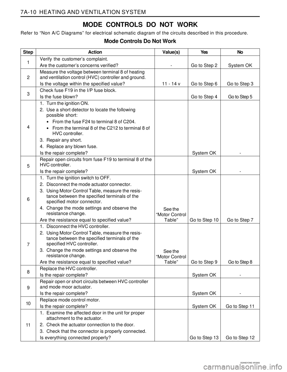
MODE CONTROLS DO NOT WORK
Refer to “Non A/C Diagrams” for electrical schematic diagram of the circuits described in this procedure.
Mode Controls Do Not Work
Step
1
2
3
4
5
6
7
8
9
10
11Action
Verify the customer’s complaint.
Are the customer’s concerns verified?
Measure the voltage between terminal 8 of heating
and ventilation control (HVC) controller and ground.
Is the voltage within the specified value?
Check fuse F19 in the I/P fuse block.
Is the fuse blown?
1. Turn the ignition ON.
2. Use a short detector to locate the following
possible short:
From the fuse F24 to terminal 8 of C204.
From the terminal 8 of the C212 to terminal 8 of
HVC controller.
3. Repair any short.
4. Replace any blown fuse.
Is the repair complete?
Repair open circuits from fuse F19 to terminal 8 of the
HVC controller.
Is the repair complete?
1. Turn the ignition switch to OFF.
2. Disconnect the mode actuator connector.
3. Using Motor Control Table, measure the resis-
tance between the specified terminals of the
specified motor connector.
4. Change the mode settings and observe the
resistance change.
Are the resistance equal to specified value?
1. Disconnect the HVC controller.
2. Using Motor Control Table, measure the resis-
tance between the specified terminals of the
specified HVC controller.
3. Change the mode settings and observe the
resistance change.
Are the resistance equal to specified value?
Replace the HVC controller.
Is the repair complete?
Repair open or short circuits between HVC controller
and mode moor actuator.
Is the repair complete?
Replace mode control motor.
Is the repair complete?
1. Examine the affected door in the unit for proper
attachment to the actuator.
2. Check the actuator connection to the door.
3. Check that the connector is properly connected.
Is everything connected properly?Yes
Go to Step 2
Go to Step 6
Go to Step 4
System OK
System OK
Go to Step 10
Go to Step 9
System OK
System OK
System OK
Go to Step 13No
System OK
Go to Step 3
Go to Step 5
-
-
Go to Step 7
Go to Step 8
-
-
Go to Step 11
Go to Step 12
Value(s)
-
11 - 14 v
See the
“Motor Control
Table”
See the
“Motor Control
Table”
Page 1513 of 2053
SSANGYONG MY2002
7A-12 HEATING AND VENTILATION SYSTEM
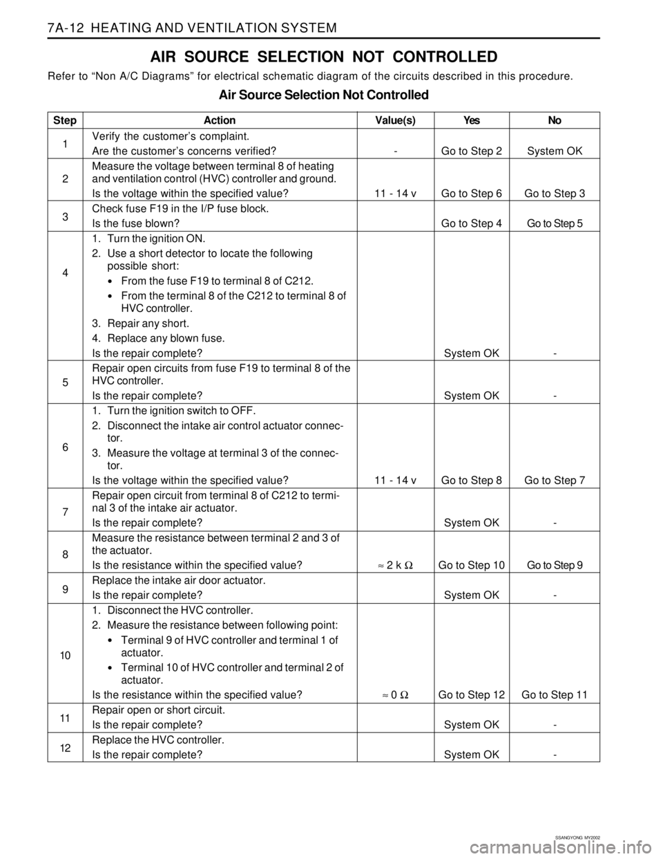
AIR SOURCE SELECTION NOT CONTROLLED
Refer to “Non A/C Diagrams” for electrical schematic diagram of the circuits described in this procedure.
Air Source Selection Not Controlled
Step
1
2
3
4
5
6
7
8
9
10
11
12Action
Verify the customer’s complaint.
Are the customer’s concerns verified?
Measure the voltage between terminal 8 of heating
and ventilation control (HVC) controller and ground.
Is the voltage within the specified value?
Check fuse F19 in the I/P fuse block.
Is the fuse blown?
1. Turn the ignition ON.
2. Use a short detector to locate the following
possible short:
From the fuse F19 to terminal 8 of C212.
From the terminal 8 of the C212 to terminal 8 of
HVC controller.
3. Repair any short.
4. Replace any blown fuse.
Is the repair complete?
Repair open circuits from fuse F19 to terminal 8 of the
HVC controller.
Is the repair complete?
1. Turn the ignition switch to OFF.
2. Disconnect the intake air control actuator connec-
tor.
3. Measure the voltage at terminal 3 of the connec-
tor.
Is the voltage within the specified value?
Repair open circuit from terminal 8 of C212 to termi-
nal 3 of the intake air actuator.
Is the repair complete?
Measure the resistance between terminal 2 and 3 of
the actuator.
Is the resistance within the specified value?
Replace the intake air door actuator.
Is the repair complete?
1. Disconnect the HVC controller.
2. Measure the resistance between following point:
Terminal 9 of HVC controller and terminal 1 of
actuator.
Terminal 10 of HVC controller and terminal 2 of
actuator.
Is the resistance within the specified value?
Repair open or short circuit.
Is the repair complete?
Replace the HVC controller.
Is the repair complete?Yes
Go to Step 2
Go to Step 6
Go to Step 4
System OK
System OK
Go to Step 8
System OK
Go to Step 10
System OK
Go to Step 12
System OK
System OKNo
System OK
Go to Step 3
Go to Step 5
-
-
Go to Step 7
-
Go to Step 9
-
Go to Step 11
-
-
Value(s)
-
11 - 14 v
11 - 14 v
≈ 2 k Ω
≈ 0 Ω
Page 1560 of 2053

SSANGYONG MY2002
7D-6 FATC-HAVC
FATC BLOCK DIAGRAM
INCAR SENSOR
AMBIENT SENSOR
WATER TEMPERATURE SENSOR
SUN LOAD SENSOR
TEMPERATURE SWITCH
BLOWER SWITCH
MODE SWITCH
DEFROSTER SWITCH
INTAKE SWITCH
AUTO SWITCH
A/CON SWITCH
OFF SWITCH
TEMP DOOR POSITION FEEDBACK
VOLTAGE
POWER TRANSISTOR COLLECTOR
VOLTAGE
VFD
MAX HI RELAY
POWER T/R
BLOWER
MOTOR
ECUCOMPRESSOR
MIX ACTUATORMIX DOOR
INTAKE ACTUATORINTAKE DOOR
MODE ACTUATORMODE DOOR
Airconditioner output
C
O
N
T
R
O
L
U
N
I
T
Page 1645 of 2053
SUPPLEMENTAL RESTRAINTS SYSTEM 8B-63
SSANGYONG MY2002
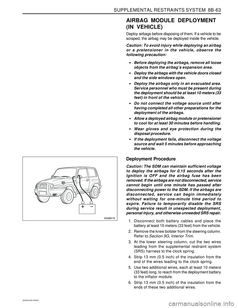
KAA8B170
AIRBAG MODULE DEPLOYMENT
(IN VEHICLE)
Deploy airbags before disposing of them. If a vehicle to be
scraped, the airbag may be deployed inside the vehicle.
Caution: To avoid injury while deploying an airbag
or a pretensioner in the vehicle, observe the
following precaution:
Before deploying the airbags, remove all loose
objects from the airbag’s expansion area.
Deploy the airbags with the vehicle doors closed
and the side windows open.
Deploy the airbags only in an evacuated area.
Service personnel who must be present during
the deployment should be at least 10 meters (33
feet) in front of the vehicle.
Do not connect the voltage source until after
having completed all other preparations for the
deployment of the airbags.
Allow a deployed airbag module or pretensioner
to cool for at least 30 minutes before handling.
Wear gloves and eye protection during the
disposal procedure.
If the deployment fails, disconnect the voltage
source and wait 5 minutes before approaching
the vehicle.
Deployment Procedure
Caution: The SDM can maintain sufficient voltage
to deploy the airbags for 0.15 seconds after the
Ignition is OFF and the airbag fuse has been
removed. If the airbags are not disconnected, service
cannot begin until one minute has passed after
disconnecting power to the SDM. If the airbags are
disconnected, service can begin immediately
without waiting for one-minute time period to
expire. Failure to temporarily disable the SRS
during service result in unexpected deployment,
personal injury, and otherwise unneeded SRS repair.
1. Disconnect both battery cables and place the
battery at least 10 meters (33 feet) from the vehicle.
2. Remove the knee bolster from the steering column.
Refer to Section 9G, Interior Trim.
3. At the lower steering column, cut the two wires
leading from the supplemental restraint system
(SRS) harness to the clock spring.
4. Strip 13 mm (0.5 inch) of the insulation from the
end of the wires leading to the clock spring.
5. Use two additional wires, each at least 10 meters
(33 feet) long, to reach from the deployment battery
to the inflator module.
6. Strip 13 mm (0.5 inch) of the insulation from the
ends of these two additional wires.
Page 1652 of 2053
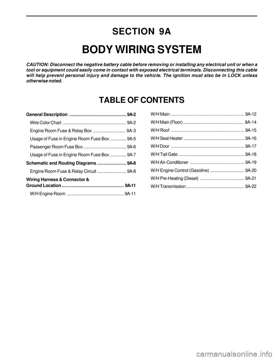
SECTION 9A
BODY WIRING SYSTEM
CAUTION: Disconnect the negative battery cable before removing or installing any electrical unit or when a
tool or equipment could easily come in contact with exposed electrical terminals. Disconnecting this cable
will help prevent personal injury and damage to the vehicle. The ignition must also be in LOCK unless
otherwise noted.
TABLE OF CONTENTS
General Description.............................................9A-2
Wire Color Chart..................................................9A-2
Engine Room Fuse & Relay Box......................... 9A-3
Usage of Fuse in Engine Room Fuse Box.............9A-5
Passenger Room Fuse Box..................................9A-6
Usage of Fuse in Engine Room Fuse Box.............9A-7
Schematic and Routing Diagrams.......................9A-8
Engine Room Fuse & Relay Circuit.......................9A-8
Wiring Harness & Connector &
Ground Location................................................. 9A-11
W/H Engine Room.............................................9A-11W/H Main..........................................................9A-12
W/H Main (Floor)............................................... 9A-14
W/H Roof..........................................................9A-15
W/H Seat Heater................................................9A-16
W/H Door..........................................................9A-17
W/H Tail Gate....................................................9A-18
W/H Air-Conditioner...........................................9A-19
W/H Engine Control (Gasoline)...........................9A-20
W/H Pre-Heating (Diesel)...................................9A-21
W/H Transmission..............................................9A-22
Page 1658 of 2053
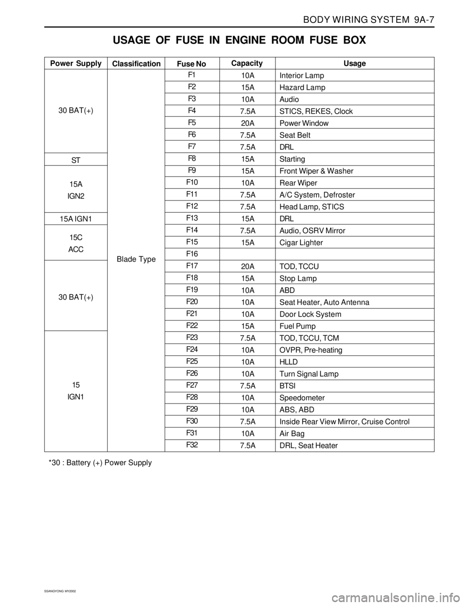
BODY WIRING SYSTEM 9A-7
SSANGYONG MY2002
USAGE OF FUSE IN ENGINE ROOM FUSE BOX
Interior Lamp
Hazard Lamp
Audio
STICS, REKES, Clock
Power Window
Seat Belt
DRL
Starting
Front Wiper & Washer
Rear Wiper
A/C System, Defroster
Head Lamp, STICS
DRL
Audio, OSRV Mirror
Cigar Lighter
TOD, TCCU
Stop Lamp
ABD
Seat Heater, Auto Antenna
Door Lock System
Fuel Pump
TOD, TCCU, TCM
OVPR, Pre-heating
HLLD
Turn Signal Lamp
BTSI
Speedometer
ABS, ABD
Inside Rear View Mirror, Cruise Control
Air Bag
DRL, Seat Heater Power SupplyUsage
Classification
Fuse NoCapacity
30 BAT(+)
ST
15A
IGN2
15A IGN1
15C
ACC
30 BAT(+)
15
IGN1
Blade TypeF1
F2
F3
F4
F5
F6
F7
F8
F9
F10
F11
F12
F13
F14
F15
F16
F17
F18
F19
F20
F21
F22
F23
F24
F25
F26
F27
F28
F29
F30
F31
F3210A
15A
10A
7.5A
20A
7.5A
7.5A
15A
15A
10A
7.5A
7.5A
15A
7.5A
15A
20A
15A
10A
10A
10A
15A
7.5A
10A
10A
10A
7.5A
10A
10A
7.5A
10A
7.5A
*30 : Battery (+) Power Supply