1997 SSANGYONG KORANDO door lock
[x] Cancel search: door lockPage 1664 of 2053
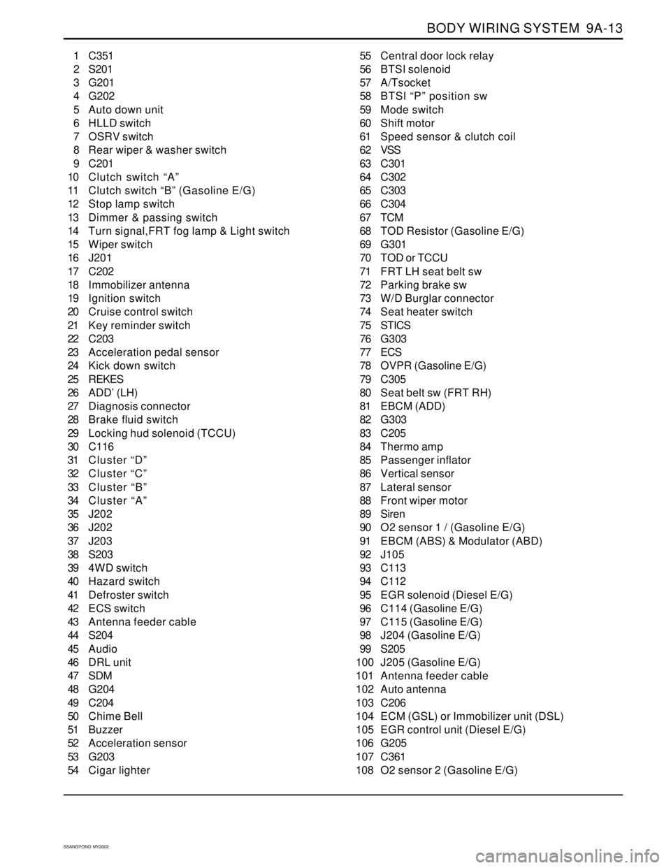
BODY WIRING SYSTEM 9A-13
SSANGYONG MY2002
1 C351
2 S201
3 G201
4 G202
5 Auto down unit
6 HLLD switch
7 OSRV switch
8 Rear wiper & washer switch
9 C201
10 Clutch switch “A”
11 Clutch switch “B” (Gasoline E/G)
12 Stop lamp switch
13 Dimmer & passing switch
14 Turn signal,FRT fog lamp & Light switch
15 Wiper switch
16 J201
17 C202
18 Immobilizer antenna
19 Ignition switch
20 Cruise control switch
21 Key reminder switch
22 C203
23 Acceleration pedal sensor
24 Kick down switch
25 REKES
26 ADD’ (LH)
27 Diagnosis connector
28 Brake fluid switch
29 Locking hud solenoid (TCCU)
30 C116
31 Cluster “D”
32 Cluster “C”
33 Cluster “B”
34 Cluster “A”
35 J202
36 J202
37 J203
38 S203
39 4WD switch
40 Hazard switch
41 Defroster switch
42 ECS switch
43 Antenna feeder cable
44 S204
45 Audio
46 DRL unit
47 SDM
48 G204
49 C204
50 Chime Bell
51 Buzzer
52 Acceleration sensor
53 G203
54 Cigar lighter55 Central door lock relay
56 BTSI solenoid
57 A/Tsocket
58 BTSI “P” position sw
59 Mode switch
60 Shift motor
61 Speed sensor & clutch coil
62 VSS
63 C301
64 C302
65 C303
66 C304
67 TCM
68 TOD Resistor (Gasoline E/G)
69 G301
70 TOD or TCCU
71 FRT LH seat belt sw
72 Parking brake sw
73 W/D Burglar connector
74 Seat heater switch
75 STICS
76 G303
77 ECS
78 OVPR (Gasoline E/G)
79 C305
80 Seat belt sw (FRT RH)
81 EBCM (ADD)
82 G303
83 C205
84 Thermo amp
85 Passenger inflator
86 Vertical sensor
87 Lateral sensor
88 Front wiper motor
89 Siren
90 O2 sensor 1 / (Gasoline E/G)
91 EBCM (ABS) & Modulator (ABD)
92 J105
93 C113
94 C112
95 EGR solenoid (Diesel E/G)
96 C114 (Gasoline E/G)
97 C115 (Gasoline E/G)
98 J204 (Gasoline E/G)
99 S205
100 J205 (Gasoline E/G)
101 Antenna feeder cable
102 Auto antenna
103 C206
104 ECM (GSL) or Immobilizer unit (DSL)
105 EGR control unit (Diesel E/G)
106 G205
107 C361
108 O2 sensor 2 (Gasoline E/G)
Page 1669 of 2053

SSANGYONG MY2002
9A-18 BODY WIRING SYSTEM
W/H TAIL GATE
1 Rear washer motor
2 Tail gate door lock actuator
3 C403 (soft top)
4 Tail gate key cylinder sw5 Rear heated glass
6 Rear wiper motor
7 Rear heated glass
KAA9A130
Page 1675 of 2053
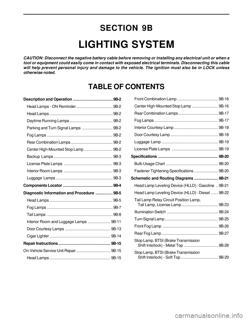
SECTION 9B
LIGHTING SYSTEM
CAUTION: Disconnect the negative battery cable before removing or installing any electrical unit or when a
tool or equipment could easily come in contact with exposed electrical terminals. Disconnecting this cable
will help prevent personal injury and damage to the vehicle. The ignition must also be in LOCK unless
otherwise noted.
TABLE OF CONTENTS
Description and Operation...................................9B-2
Head Lamps - ON Reminder................................9B-2
Head Lamps........................................................9B-2
Daytime Running Lamps......................................9B-2
Parking and Turn Signal Lamps...........................9B-2
Fog Lamps..........................................................9B-2
Rear Combination Lamps.....................................9B-2
Center High-Mounted Stop Lamp.........................9B-2
Backup Lamps....................................................9B-3
License Plate Lamps ...........................................9B-3
Interior Room Lamps ...........................................9B-3
Luggage Lamps..................................................9B-3
Components Locator............................................9B-4
Diagnostic Information and Procedure...............9B-5
Head Lamps........................................................9B-5
Fog Lamps..........................................................9B-7
Tail Lamps..........................................................9B-8
Interior Room and Luggage Lamps....................9B-11
Door Courtesy Lamps ........................................9B-13
Cigar Lighter......................................................9B-14
Repair Instructions..............................................9B-15
On-Vehicle Service Unit Repair..............................9B-15
Head Lamps......................................................9B-15Front Combination Lamp....................................9B-16
Center High-Mounted Stop Lamp.......................9B-16
Rear Combination Lamps...................................9B-17
Fog Lamps........................................................9B-17
Interior Courtesy Lamp .......................................9B-18
Door Courtesy Lamp ..........................................9B-18
Luggage Lamp..................................................9B-19
License Plate Lamps .........................................9B-19
Specifications.....................................................9B-20
Bulb Usage Chart..............................................9B-20
Fastener Tightening Specifications.....................9B-20
Schematic and Routing Diagrams.....................9B-21
Head Lamp Leveling Device (HLLD) : Gasoline ..9B-21
Head Lamp Leveling Device (HLLD) : Diesel......9B-22
Tail Lamp Relay Circuit Position Lamp,
Tail Lamp, License Lamp................................9B-23
Illumination Switch.............................................9B-24
Turn Signal Lamp...............................................9B-25
Front Fog Lamp.................................................9B-26
Rear Fog Lamp..................................................9B-27
Stop Lamp, BTSI (Brake Transmission
Shift Interlock) - Metal Top..............................9B-28
Stop Lamp, BTSI (Brake Transmission
Shift Interlock) - Soft Top.................................9B-29
Page 1719 of 2053

SSANGYONG MY2002
9E-2 INSTRUMENTATION, DRIVER INFORMATION
DESCRIPTION AND OPERATION
CIGAR LIGHTER
The cigar lighter is located in the front portion of the
floor console. To use the lighter, push it in completely.
When the lighter is hot, it will release itsef from contact
with the heating element. The lighter and the heating
element can be damaged if the lighter does not fully
release itsef from the heating element.
ASHTRAY
The ashtray is located in the console. To access the
ashtray, pullit out of the ashtray housing. The ashtray
lamp will go on when the parking lamps or headlamps
are turned on.
INSTRUMENT PANEL VENTS
The center and the side vents in the instrument panel
can be adjusted up and down and from side to side.
The side vents can also be aimed toward the side
windows to defog them.
GLOVE BOX
The glove box can be opened by pulling upon the latch
handle.
DIGITAL CLOCK
The digital clock is located in the instrument cluster.
INSTRUMENT CLUSTER
The instrument cluster is located above the steering
column and in the instrument cluster trim panel. The
instrument cluster contains the instruments that
provide the driver with vehicle performance information.
The instrument cluster contains a speedometer, a
tachometer, an odometer, a trip odometer, a
temperature gauge, a fuel gauge, and several indicator
lamps. For replacement of the indicator lamp bulbs
contained in the instrument cluster, refer to “Instrument
Cluster Indicator Lamps Specifications” in the section.
SPEEDOMETER AND
TACHOMETER
The speedometer measures the speed of the vehicle
in km/h (with mph) or mph (with km/h). It consists of
an instrument cluster gauge connected to the vehicle
speed sensor on the transaxle output shaft. The
tachometer measures the engine’s speed in terms of
thousands of revolutions per minute. It consists of an
instrument cluster gauge connected to a sending unit
in the engine con-trol module. Do not operate the
engine in the red zone. Engine damage may occur.
TRIP ODOMETER
The trip odometer measures the distance the vehicle
has traveled since it was last reset. It consists of an
instrument cluster gauge connected to the sending unit
on the tasnsaxle output shaft. The trip oddometer can
be record the distance traveled from any starting point.
FUEL GAUGE
The fuel gauge consists of an instrument cluster gauge
connected to a sending unit in the fuel tank. The fuel
gauge indicates the quantity of fuel in the tank only
when the ignition is turned to ON or ACC. When the
ignition is turned to LOCK or START, the pointer may
come to rest at any position.
TEMPERATURE GAUGE
The temperature gauge consists of an instrument
cluster gauge connected to a temperature sensor that
is in con-tact with the circulating engine coolant. The
temperature gauge indicates the temperature of the
coolant. Prolonged driving or idling in very hot weather
may cause the pointer to move beyond the center of
the gauge. The engine is overheating if the pointer
moves into the red zone at the upper limit of the gauge.
INSTRUMENT CLUSTER
INDICATOR LAMPS
The instrument cluster contains indicator lamps that
indicatethe functioning of certain systems or the
existenceof potential problems with the operation of
the vehicle. The indicator lamps are replaceable. For
replacement of the indicator lamps contained in the
instrument cluster, refer to “instrument cluster indicator
lamps specifications” in this section.
CHIME MODULE
The chime module will sound to bring attention to one
or more of the following conditions:
The lights are on and the ignition not in ACC, ON,
or START.
The ignition key is in the ignition switch when the
driver’s side door is open.
The seat belt is unbuckled when the ignition is in
ACC, ON, or START.
Voltage is supplied at all times through the fuse block
to power the chime module.
Page 1744 of 2053
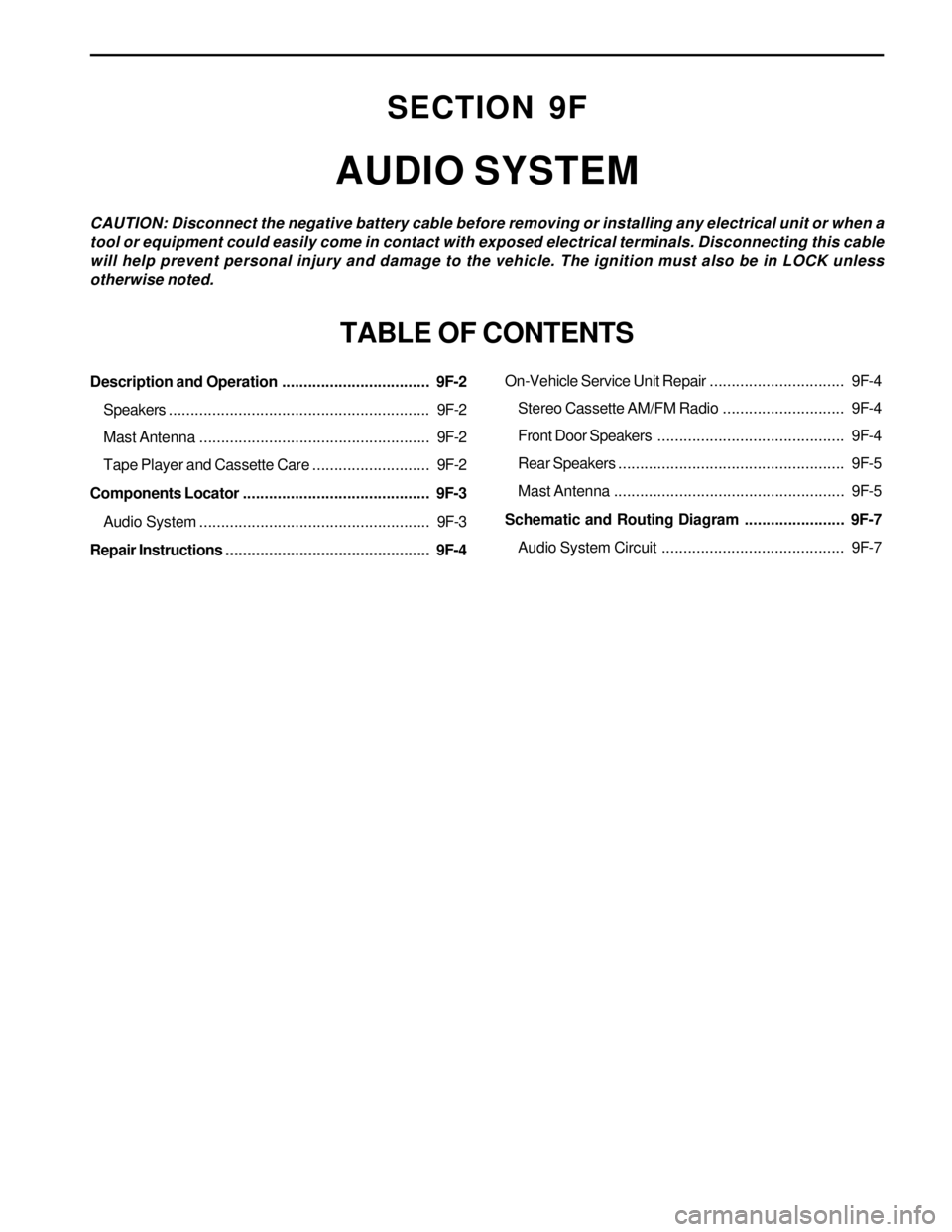
Description and Operation.................................. 9F-2
Speakers............................................................ 9F-2
Mast Antenna..................................................... 9F-2
Tape Player and Cassette Care........................... 9F-2
Components Locator ........................................... 9F-3
Audio System..................................................... 9F-3
Repair Instructions............................................... 9F-4
SECTION 9F
AUDIO SYSTEM
CAUTION: Disconnect the negative battery cable before removing or installing any electrical unit or when a
tool or equipment could easily come in contact with exposed electrical terminals. Disconnecting this cable
will help prevent personal injury and damage to the vehicle. The ignition must also be in LOCK unless
otherwise noted.
TABLE OF CONTENTS
On-Vehicle Service Unit Repair............................... 9F-4
Stereo Cassette AM/FM Radio............................ 9F-4
Front Door Speakers........................................... 9F-4
Rear Speakers.................................................... 9F-5
Mast Antenna..................................................... 9F-5
Schematic and Routing Diagram....................... 9F-7
Audio System Circuit .......................................... 9F-7
Page 1750 of 2053
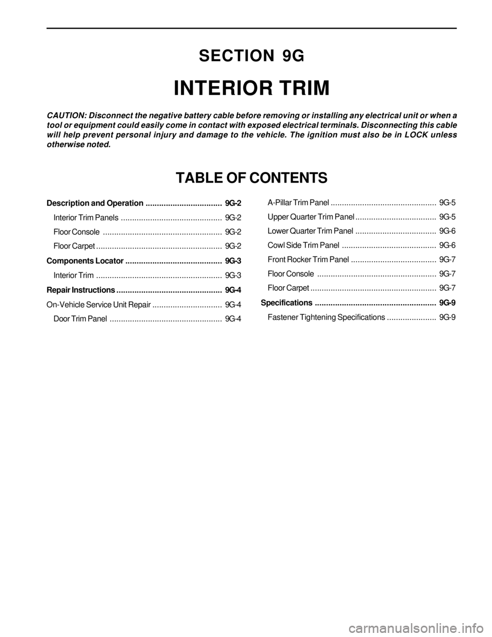
Description and Operation..................................9G-2
Interior Trim Panels.............................................9G-2
Floor Console.....................................................9G-2
Floor Carpet........................................................9G-2
Components Locator ...........................................9G-3
Interior Trim........................................................9G-3
Repair Instructions...............................................9G-4
On-Vehicle Service Unit Repair...............................9G-4
Door Trim Panel..................................................9G-4
SECTION 9G
INTERIOR TRIM
CAUTION: Disconnect the negative battery cable before removing or installing any electrical unit or when a
tool or equipment could easily come in contact with exposed electrical terminals. Disconnecting this cable
will help prevent personal injury and damage to the vehicle. The ignition must also be in LOCK unless
otherwise noted.
TABLE OF CONTENTS
A-Pillar Trim Panel...............................................9G-5
Upper Quarter Trim Panel....................................9G-5
Lower Quarter Trim Panel....................................9G-6
Cowl Side Trim Panel ..........................................9G-6
Front Rocker Trim Panel......................................9G-7
Floor Console.....................................................9G-7
Floor Carpet........................................................9G-7
Specifications......................................................9G-9
Fastener Tightening Specifications......................9G-9
Page 1777 of 2053
SSANGYONG MY2002
9J-2 WINDNOISE
DIAGNOSIS
WINDNOISE DIAGNOSIS
Caution: An assistant should drive the vehicle while
the technician checks for the location of the wind-
noise, in order to prevent personal injury or vehicle
damage.
A test drive in the vehicle is necessary to accurately
determine the location of the windnoise. Often there is
a primary leak and secondary leaks. Failure to repair
all leaks will only reduce the windnoise, not eliminate
it.
During the test drive the technician should bring the
following items to aid in determining the location of
the windnoise.
•A mechanics stethoscope or vacuum hose
Masking tape
Strip caulk
A china marking pencil
A screwdriver
Perform the following steps in order to conduct the
road test:
1. Choose a route that includes smooth straight
streets that run in all four directions (north, south,
east, and west).
2. Choose streets with little traffic or noise that would
interfere with the test.
3. Drive the vehicle at the speeds at which the noise
was noticed by the customer or until the noise is
produced. Do not exceed legal speed limits.
4. The windnoise is external if any of the following
conditions occur:
The windnoise is caused by the wind.
The windnoise can be heard with the door glass
lowered and while the vehicle is being driven.
The windnoise is eliminated when tape is placed
over various moldings and gaps.5. Internal windnoise is air leaving the vehicle and
should be repaired in the following manner.
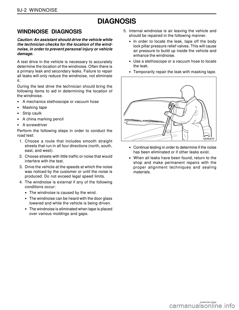
In order to locate the leak, tape off the body
lock pillar pressure relief valves. This will cause
air pressure to build up inside the vehicle and
enhance the windnoise.
Use a stethoscope or a vacuum hose to locate
the leak.
Temporarily repair the leak with masking tape.
Continue testing in order to determine if the noise
has been eliminated or if other leaks exist.
When all leaks have been found, return to the
shop and make permanent repairs with the
proper alignment techniques and sealing
materials.
KAA9J010
Page 1781 of 2053

SQUEAKS AND RATTLES 9K-3
SSANGYONG MY2002
Check for a lack of lubrication of the door hinge pins.ChecksActionOperate the doors and listen for squeaks.
Lubricate the door hinge pins with light oil and coat
with lithium grease.
Squeak Coming From Console When Shifting Manual Transaxle
(Condition Occurs In Cold Weather with a Cold Engine)
Check the manual transaxle control lever lower boot.ChecksActionMove the control lever between gears and listen for
squeaks.
Remove the floor console and replace the lower shift
boot or apply talcum powder to the lower shift boot.
Squeak When Operating Doors
Check for vibration of the fuse box cover against the
instrument panel side trim.ChecksActionTap on thecoverwith a fingerandlisten fora buzz.
Apply 6.35 mm (0.250 inch) by 25.4 mm (1.00 inch)
felt pads to the side trim where the cover makes
contact.
Squeak Coming From Instrument Cluster Trim Plate
Check for rubbing of the cluster trim plate on the
instrument panel.ChecksActionTest drive the vehicle in order to verify this condi-
tion.
Remove the instrument cluster trim plate and install
felt tape to the edges.
Buzz From the Left Side of Instrument Panel
Check the door lock solenoid.
Check for rattling electrical connectors inside the door
trim panel.ChecksActionRemove the door trim panel and check if the sole-
noid is loose.
Tighten the solenoid bolts.
Tap on the trim panel and listen for a rattle.
Remove the trim panel and wrap foam padding
around the connectors as required.
Rattle Coming From Door