1997 SSANGYONG KORANDO door lock
[x] Cancel search: door lockPage 1783 of 2053
SECTION 9L
GLASS AND MIRRORS ON
CAUTION: Disconnect the negative battery cable before removing or installing any electrical unit or when a
tool or equipment could easily come in contact with exposed electrical terminals. Disconnecting this cable
will help prevent personal injury and damage to the vehicle. The ignition must also be in LOCK unless
otherwise noted.
TABLE OF CONTENTS
Description and Operation...................................9L-2
Stationary Glass..................................................9L-2
Inside Rearview Mirror.........................................9L-2
Outside Rearview Mirrors.....................................9L-2
Components Locator............................................9L-3
Glass and Mirror..................................................9L-3
Repair Instructions................................................9L-4
On-Vehicle Service Unit Repair................................9L-4
Windshield..........................................................9L-4
Rear Window Glass.............................................9L-6
Rear Window Defogger Braided Lead
Wire Repair......................................................9L-7Rear Window Defogger Grid Line Repair..............9L-8
Front Door Glass..................................................9L-9
Fixed Glass.........................................................9L-9
Inside Rearview Mirror ....................................... 9L-10
Outside Rearview Mirror..................................... 9L-10
Specifications.....................................................9L-11
Fastener Tightening Specifications..................... 9L-11
Schematic and Routing Diagram......................9L-12
Defroster........................................................... 9L-12
Inside Rear View Mirror (Dimming) &
Backup Lamp................................................. 9L-13
Page 1796 of 2053
Description and Operation..................................9M-2
Emblems and Lettering.......................................9M-2
Mud Guards.......................................................9M-2
Components Locator ...........................................9M-3
Exterior Trim.......................................................9M-3
Repair Instructions...............................................9M-4
On-Vehicle Service Unit Repair...............................9M-4
B-Pillar Molding..................................................9M-4
B-Pillar Cover......................................................9M-4
SECTION 9M
EXTERIOR TRIM
CAUTION: Disconnect the negative battery cable before removing or installing any electrical unit or when a
tool or equipment could easily come in contact with exposed electrical terminals. Disconnecting this cable
will help prevent personal injury and damage to the vehicle. The ignition must also be in LOCK unless
otherwise noted.
TABLE OF CONTENTS
Air Extractor Grille...............................................9M-4
Door Molding......................................................9M-5
Front Wheel Molding...........................................9M-5
Rear Wheel Molding...........................................9M-5
Side Step...........................................................9M-6
C-Pillar Cover......................................................9M-6
Roof Molding......................................................9M-6
Specifications......................................................9M-7
Fastener Tightening Specifications......................9M-7
Page 1819 of 2053
SECTION 9P
DOORS
CAUTION: Disconnect the negative battery cable before removing or installing any electrical unit or when a
tool or equipment could easily come in contact with exposed electrical terminals. Disconnecting this cable
will help prevent personal injury and damage to the vehicle. The ignition must also be in LOCK unless
otherwise noted.
TABLE OF CONTENTS
Description and Operation...................................9P-2
Power Door Locks................................................9P-2
Power Windows...................................................9P-2
Door Lock Striker.................................................9P-2
Components Locator............................................9P-3
Doors ..................................................................9P-3
Repair Instructions................................................9P-4
On-Vehicle Service Unit Repair................................9P-4
Door Glass Run...................................................9P-4
Door Side Opening Weatherstrip..........................9P-4
Door Lock Striker.................................................9P-4
Door Lock Striker Adjustment...............................9P-5
Front Door Lock...................................................9P-6
Inside Door Handle..............................................9P-7
Outside Door Handle ...........................................9P-7Door Lock Cylinder..............................................9P-7
Power Window Regulator.....................................9P-8
Front Door Assembly ...........................................9P-8
Tail Gate Assembly.............................................9P-8
Door Hinge..........................................................9P-9
Door Hold Open Link ...........................................9P-9
Outside Channel Molding.....................................9P-9
Door Weatherstrip................................................9P-9
Door Seal Trim...................................................9P-10
Specifications.....................................................9P-11
Fastener Tightening Specifications.....................9P-11
Schematic and Routing Diagrams.....................9P-12
Central Door Locks System................................9P-12
Power Windows.................................................9P-13
Page 1820 of 2053
SSANGYONG MY2002
9P-2 DOORS
DESCRIPTION AND OPERATION
POWER DOOR LOCKS
The power door locks use a solenoid that is contained
in each door lock assembly. The door locks are
activated by the actuator on the inside door handle or
by the lock cylinder on the driver’s side door only.
When the driver’s side door is locked or unlocked by
the actuator or lock cylinder, all doors are locked or
unlocked accordingly.
POWER WINDOWS
The power windows are controlled by electrical
switches on the door trim center upper panel and areoperated by a motor at each window regulator. The
windows are lowered by pressing the switch and are
raised by pulling up on the switch. The window will
stop movement when the switch is released or when
the windowis completely open or closed.
DOOR LOCK STRIKER
The front door lock strikers each consist of a striker
with two screws threaded into a floating cage plate in
the B-pillars. The door lock fork snaps over and engages
the striker.
Page 1821 of 2053
SSANGYONG MY2002
9P-4 DOORS
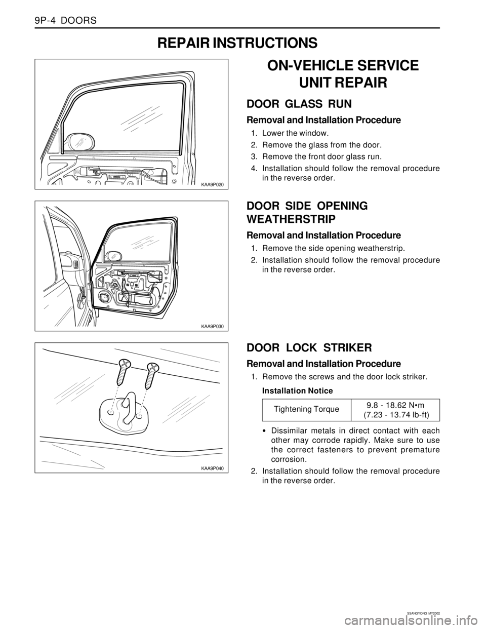
DOOR LOCK STRIKER
Removal and Installation Procedure
1. Remove the screws and the door lock striker.
Installation Notice
Dissimilar metals in direct contact with each
other may corrode rapidly. Make sure to use
the correct fasteners to prevent premature
corrosion.
2. Installation should follow the removal procedure
in the reverse order.
KAA9P020
ON-VEHICLE SERVICE
UNIT REPAIR
DOOR GLASS RUN
Removal and Installation Procedure
1. Lower the window.
2. Remove the glass from the door.
3. Remove the front door glass run.
4. Installation should follow the removal procedure
in the reverse order.
REPAIR INSTRUCTIONS
KAA9P030
DOOR SIDE OPENING
WEATHERSTRIP
Removal and Installation Procedure
1. Remove the side opening weatherstrip.
2. Installation should follow the removal procedure
in the reverse order.
Tightening Torque9.8 - 18.62 Nm
(7.23 - 13.74 lb-ft)
KAA9P040
Page 1822 of 2053
DOORS 9P-5
SSANGYONG MY2002
DOOR LOCK STRIKER
ADJUSTMENT
Installation Notice:
The door lock striker is an important attaching part
that can affect the performance of vital components
and systems and can cause major repair expenses. If
replacement becomes necessary, the door lock striker
must be replaced by one with the same part number
or with an equivalent part. Do not use a replacement
part of lesser quality or of a substitute design. The
specified torque values must be used during
reassembly in order to ensure the proper retention of
the part.
The door lock striker consists of a striker with two screws
that are threaded into a tapped, floating cage plate
located in the appropriate body pillar. This floating
cage plate allows the striker to be easily adjusted in
or out and up or down. The door is secured in the closed
position when the door lock fork snaps over and
engages the striker.
Fore/Aft Adjustment
1. The door must be properly aligned.
2. Close the door until the lock fork contacts the
striker.
3. Stand next to the door opening and move the door
slowly in and out, just touching the striker each
time.
4. The alignment of the lock fork and the striker can
be easily seen. The lock fork should be
perpendicular to and fall near the middle of the
striker between the B-pillar and the end of the
striker.
5. If a fore or aft adjustment is required, use the
following steps:
5.1 Remove the striker screws.
5.2 Remove the spacer in order to move the striker
toward the front of the vehicle.
5.3 Add a 2 mm (0.8 inch) spacer in order to move
the striker toward the front of the vehicle.
5.4 Install the striker screws.
6. Perform the up/down or the in/out adjustment.
Refer to “up/down or in/out Adjustment” in this
section.
Page 1823 of 2053
SSANGYONG MY2002
9P-6 DOORS
KAA9P050
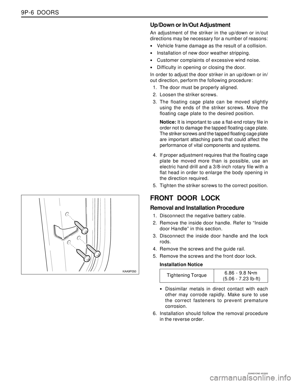
FRONT DOOR LOCK
Removal and Installation Procedure
1. Disconnect the negative battery cable.
2. Remove the inside door handle. Refer to “Inside
door Handle” in this section.
3. Disconnect the inside door handle and the lock
rods.
4. Remove the screws and the guide rail.
5. Remove the screws and the front door lock.
Installation Notice
Dissimilar metals in direct contact with each
other may corrode rapidly. Make sure to use
the correct fasteners to prevent premature
corrosion.
6. Installation should follow the removal procedure
in the reverse order.
Up/Down or In/Out Adjustment
An adjustment of the striker in the up/down or in/out
directions may be necessary for a number of reasons:
Vehicle frame damage as the result of a collision.
Installation of new door weather stripping.
Customer complaints of excessive wind noise.
Difficulty in opening or closing the door.
In order to adjust the door striker in an up/down or in/
out direction, perform the following procedure:
1. The door must be properly aligned.
2. Loosen the striker screws.
3. The floating cage plate can be moved slightly
using the ends of the striker screws. Move the
floating cage plate to the desired position.
Notice: It is important to use a flat-end rotary file in
order not to damage the tapped floating cage plate.
The striker screws and the tapped floating cage plate
are important attaching parts that could affect the
performance of vital components and systems.
4. If proper adjustment requires that the floating cage
plate be moved more than is possible, use an
electric hand drill and a 3/8-inch rotary file with a
flat head in order to enlarge the body opening in
the direction required.
5. Tighten the striker screws to the correct position.
Tightening Torque6.86 - 9.8 Nm
(5.06 - 7.23 lb-ft)
Page 1824 of 2053
DOORS 9P-7
SSANGYONG MY2002
KAA9P060
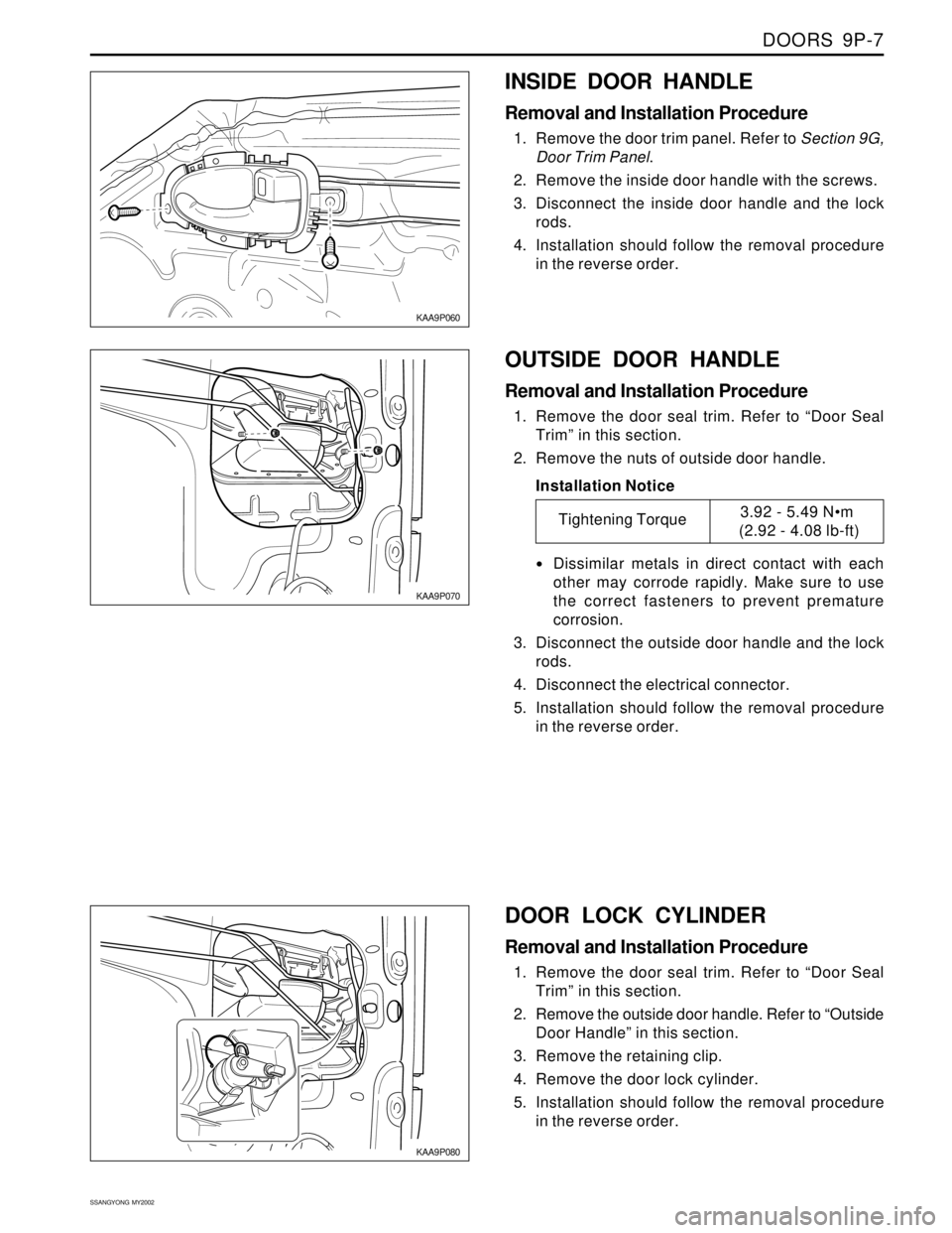
INSIDE DOOR HANDLE
Removal and Installation Procedure
1. Remove the door trim panel. Refer to Section 9G,
Door Trim Panel.
2. Remove the inside door handle with the screws.
3. Disconnect the inside door handle and the lock
rods.
4. Installation should follow the removal procedure
in the reverse order.
KAA9P070
KAA9P080
OUTSIDE DOOR HANDLE
Removal and Installation Procedure
1. Remove the door seal trim. Refer to “Door Seal
Trim” in this section.
2. Remove the nuts of outside door handle.
Installation Notice
Dissimilar metals in direct contact with each
other may corrode rapidly. Make sure to use
the correct fasteners to prevent premature
corrosion.
3. Disconnect the outside door handle and the lock
rods.
4. Disconnect the electrical connector.
5. Installation should follow the removal procedure
in the reverse order.
DOOR LOCK CYLINDER
Removal and Installation Procedure
1. Remove the door seal trim. Refer to “Door Seal
Trim” in this section.
2. Remove the outside door handle. Refer to “Outside
Door Handle” in this section.
3. Remove the retaining clip.
4. Remove the door lock cylinder.
5. Installation should follow the removal procedure
in the reverse order.
Tightening Torque3.92 - 5.49 Nm
(2.92 - 4.08 lb-ft)